Thursday, November 28, 2024

Beverage Lightning Strike 3: Am I Out?

In late summer there was a DXpedition (I forget which) that prompted me to look for them on 160 meters. I had just modified my antenna selection software to include the 160 meter mode of the 80 meter array. It's not a great antenna on 160 (base loaded 80 meter vertical) but at least I have it; the primary 160 meter antenna is not available during farming season because the radials are rolled away.

The northeast-southwest and east-west Beverages were intermittent and the north-south Beverage didn't seem to work at all. I suspected a fault in the remote Beverage switch. I did bother attempting a repair until after the hay harvest, and then I was distracted by more urgent antenna projects. 160 meters was not a priority until early fall and wasn't free to look into the problem until late October. By then I had to move quickly because major contests were on the horizon and there were several ongoing DXpeditions that I needed on 160.

[Note: Rather than repeat technical detail, please follow the links to the articles where that detail is provided. This includes each Beverage, the switching system, lightning damage and protection measures. Without that background, parts of this article may be mystifying.]

My first step was to open the head end for the north-south Beverage. There was some copper-coloured water pooling in the bottom. I noticed that the orientation of the box had the weep holes on top, which let water in but not out. I poured out the water and brought it indoors for a closer inspection.

That was when I noticed that the problem went well beyond a bit of water. The components and wires near the corner where the water pooled were easily pulled off the PCB. I removed the head end from its enclosure and turned over the PCB.

Yikes! It was lightning, not water damage. This was the third time in just a few short years. Here are links to the first and second instances.

Tracing suggested that the lightning travelled from (or to) both inner and outer conductors of the RG6 run to the Beverage switch. There is a GDT (gas discharge tube) from the centre conductor to the ground terminal but lightning from the outer conductor jumped across the PCB pads to reach the GDT. The solder was blown off and so were a couple of component leads. The picture was taken after I removed damaged components and cleaned most of the char from the pads.

I walked to the basement patch panel and did a resistance check of the control lines to the Beverage switch. There was an open circuit to the relay for the north-south Beverage, while the others had the expected resistance for the relay coils. I disconnected the switch and brought it indoors. There was no visible lightning damage. I repeated the resistance check and got the same result. At least the long run of control cable appeared to have survived.

I don't know when the lightning damage occurred. Perhaps I wasn't home at the time or I didn't notice a particularly close strike. After protecting all the head ends with GDTs, I chose to leave them in place over the summer in case I needed them to chase the occasional DX with the base-loaded vertical. That may have been a mistake, or perhaps the mistake was that I had not yet placed GDTs on the control lines or the Beverage ports at the switch. But I really should have done both.

Direct testing of the other two Beverages at the switch showed that they were behaving normally. I patched the northeast-southwest Beverage to the transmission line back to the shack and it tested good -- that meant that I could temporarily get by with that and the short east-west Beverage. None of the other coax runs or head ends were damaged, or at least not to the point of malfunction. Lightning may have reached them and they are protected by their GDTs. My time was limited so I decided to ignore them until later. An inspection is warranted despite their proper functioning.

Fearing more damage, I retrieved the reflection transformer from the end of the north-south Beverage. Other than some insect debris that I cleaned out, the transformer looked and tested good.

Here is where the peculiarities of lightning surprised me. Other than the components and solder being blown off the PCB and leads burned off, there was no damage! One of the two 0.1 μF coupling capacitors had one lead burned off right to the capacitor body. Yet it tested good, as did the other. The RFC was similarly fine despite one blackened lead. The DPDT relay also worked. There was an unrelated cold solder joint that was dislodged by my handling, not by lightning, which I repaired.

Since the PCB has plenty of space, I cleaned and then soldered the damaged wires and components to clean pads. With that done the head end worked as designed. You will notice that the GDT and resistor assemblies were removed. Although GDT will handle numerous lightning surges, the number of them it can endure depends on their peak current and duration. The parallel 33 kΩ resistor increases GDT life by providing a continuous discharge path for charges that can build up on the long Beverage wires from precipitation static and distant lightning.

The datasheet for the Bourns 2057-07 provides estimates for the type and number of surges the GDT will survive. Unfortunately there is no easy way to learn its condition when it's deployed in the field. Since a GDT fails open, it will pass a resistance test.

The GDT displayed evidence of a strong surge. The picture is of the one that I believe took the brunt of it. The GDT-resistor assembly measures open despite the resistor. When isolated, the resistor tests normal. Although my phone camera won't focus at a very close distance, there is just enough resolution to explain the measurements. It is clearer with inspected with magnifying glasses.

The solder on the front (bottom) lead is mostly gone! It is better on the other side but there was a powdery white residue that was easily scraped off with a pointed tool. Since there was enough energy through the GDT to melt or ablate the solder on the leads, I believe the GDT ought to be replaced. 

I will do the other two as well just to be certain. They are inexpensive to replace -- I bought 100 of them -- but a few minutes must be spent doing the replacement, including the resistors. I am also thinking of adding a fourth GDT to the coax centre conductor for complete coverage of the wires entering the head end.

Since we're past lightning season and I was pressed for time leading up to CQ WW CW, I deferred the job. I will also have to inspect the head ends of the other Beverages for signs of lightning damage since they share a common ground at the remote switch. There is time before the 2025 storm season.

We're not done yet. The remote switch was damaged and also had to be repaired. There was no visible damage despite knowing that it had failed. It was easy to confirm with an ohmmeter that all of the relays needed to be replaced.

I cut out and discarded the damaged SPDT reed relays. The copper windings of the output transformer were so corroded that I cut them off the ferrite binocular core and wound a new one from insulated tinned wire. The repeated insect infestations brought a lot of moisture into the enclosure. It's an impossible choice between weep holes and blocking entry to the tiny insects that can fit through the weep holes.

Reed relays work well for small signal switching, and that's what I went with the previous time the switch was damaged. However they are typically twice as expensive as conventional sealed relays. I have a stock of Omron G5V DPDT relays, and with only 3 days until CQ WW CW I decided to use them. There are better choices available even if the G5V is good enough.

I selected a small proto board to mount the components. It fits into the small space between the barrier strip and F connectors. To ease maintenance I used 16-pin DIP sockets to mount the relays. I had exactly three left from my decades old stock!

Since the relays are DPDT and the switch requires SPDT, I wired the two sides in parallel. If one set of contacts develops excess resistance, my hope is that the other set will provide redundancy. That is, if they don't age at the same rate! In case of degradation or lightning damage, the sockets allow for easy substitution.

I tested the RF and DC paths once it was assembled. There are 4 DC control lines for the coils of the 3 Beverage selector relays and one that feeds DC via a bias-T circuit to reverse the Beverage. There is a fifth control line for ground. The 5 lines pass through RF chokes.

All of the conductors into the enclosure ought to be protected with GDT. I will do that later. It's so tight inside the enclosure that I may need to move the switch to a larger one.

Here's a picture of the completed switch. The circuit is unchanged but it has a different format. The 3 control lines on the left are for selecting each Beverage, and the next 3 are currently unused. the rightmost control lines are for reversing the selected Beverage (via a bias-T) and ground. The PCB sits freely since the small proto board has no mounting holes. Cardboard isolates the PCB from the enclosure surface (ground). Plastic is a better choice since cardboard will absorb moisture. I'll deal with that when I pull the switch after the winter season for further work.

The Cat5 cable is about one foot long and is connected to the long Cat5 cable to the shack with crimp connectors. The reason for this change is to make it easier to remove the switch for service. The day before CQ WW CW was close to freezing and it was raining. I had no choice but to work outside in the miserable weather, but I tried to simplify the task with those crimps. I was relieved that the Beverage system was once again operational. It came in very handy on 160 meters during the contest.

Strike 3: am I out?

Beverages are simple and effective directional receive antennas for the low bands. That's hard to beat. However they have their quirks. One is the risk to the long wires from weather, wildlife and trees (growth and dead fall). Another is lightning. Strikes from nearby lightning induces a large voltage and current flow along those long conductors, and that energy has to go somewhere. Direct strikes are of course worse though less likely.

I can keep repairing the antennas and continue to improve lightning mitigation measures. They can be disconnected during the spring to early fall storm months but that would require temporary reconnection or other receive antenna solutions for summer contests and DXpeditions.

The obvious alternative is vertical arrays. These range from compact pennants to large receive 4-squares and 8-circle arrays. They are more immune to lightning and the latter two can outperform Beverages. They also have disadvantages. They are so complex that in most cases it is better to buy an expensive commercial product than to build one from scratch. 

A second problem is that they require pre-amps since they are very inefficient. For the top band DXer that is not an impediment, but it is for multi-op and SO2R contests. Filters and other measures are typically required to prevent the other stations' transmissions from overloading the pre-amps of the vertical receive array. I know contesters that had removed these systems from their stations for this very reason despite their superior performance.

I have enough land that I could install a vertical receive array far from the transmit antennas. Perhaps I will. If it works out I could decide whether to abandon the Beverage or to use the new antenna to complement the Beverages. 

Future lightning repairs to the Beverages might eventually push me to make the switch.

Thursday, November 21, 2024

Analyzing the Wrong Things

I expect that everyone knows the following old joke. One night a passerby sees a drunk on his hands and knees searching the pavement at the base of a lamp post. He asks and is told that the drunk is looking for his keys. The passerby sees nothing on the ground and asks if he's sure that he dropped the keys there. The drunk answers, no, but the light is better there.

The joke resonates because, even cold sober, we have all done something similar. We look for answers where we are comfortable searching even if we strongly suspect the answer lies elsewhere. Worse, we may decide the answer in advance and search for affirmation.

Hams often fall into the same trap since, despite this being a technical hobby, many of us don't always have the required technical skills or tools. Simple and wrong answers abound, and in many cases you can still get by despite getting it wrong.

Probably the best known example is SWR. Decades ago when I was young and new to amateur radio, you tuned your tube transmitter for maximum "smoke" and hoped for the best. There was no easy way to determine if the antenna was resonant, presented a good match or met the advertised specifications. 

The only affordable and easily employed tool was the SWR bridge. A low SWR became synonymous with a properly working antenna system. That would be nice were it true, but it isn't. It's just easy to measure, like the drunk under the lamp post. So we convince ourselves that an SWR of 1 is the ultimate objective.

There are many similar examples that I can think of, and probably so can you. That's not the purpose of this article. Nor is it to ridicule hams for a lack of knowledge; no one can know everything. The objective should be for all of us to learn and, where appropriate, to teach.

Certainly we have the resources to do diligent product research and the money to buy good transceivers and test equipment. What makes them so good and how can we tell? If we don't have the knowledge to measure and understand, are we to trust marketing brochures or the opinions of other hams? What do we analyze and how do we analyze?

Let me give a personal example. Around 1990 I purchased my first PC, a 286 or 386 running DOS. Although I was a software professional with access to mainframes, I made the purchase for one reason: ELNEC. I had an abiding interest in antennas from the 1980s and the public availability of MININEC brought the ability to design antennas from first principles. I was eager to get started. Until then I would write my own software and spreadsheets to produce variations of standard yagi designs using formulae from W2PV ("Yagi Antenna Design") and others. My knowledge extended no further.

My most elaborate models had so many segments that runs would take an hour or more. That was no problem: I would start it before the evening meal and read the results afterwards. Although ELNEC/MININEC had its limitations that I regularly ran into headfirst, I still learned a lot and used it as the basis for 40 meter wire yagis and other antennas that were compatible with my modest station.

One of those antennas was an 80 meter half-sloper. I built and tuned it based on myth and lore, and I was pretty happy with the DX I could work. At the time (recently transplanted from VE4) the novelty of working DX on 80 meter coloured my view of how well the antenna performed and how it functioned.

I went ahead and built a model for it in ELNEC, hoping to gain insights that would help me to make it better. But this is not an antenna that models well with the MININEC engine. I tried to get around those limitations with load objects to simulate ground interactions, the coax run up the tower and the effect of yagis on top. Eventually I got an SWR curve that closely matched what I measured -- with an SWR/power bridge, not an antenna analyzer -- and performance that kinda sorta reflected my experience with it.

Years later when I fed the same model into the more accurate and comprehensive EZNEC and NEC2, it produced completely different results. My earlier trial-and-error approach to antenna design was exposed as an abject failure. Stripping off all the crud from the model resulted in a more truthful outcome that showed me just how poor the antenna really was. I had no idea what I was doing. The DX in my log didn't disappear but perhaps I could have done better with a different antenna, and by avoiding analysis errors.

When hams get excited about downloading the now free EZNEC (or one of the other free modelling programs) with stars in their eyes about the great antennas they were going to design, I politely try to inject a little reality. Software is not judgmental: feed it garbage and it produces garbage. EZNEC will warn you away from some common stupidities but most will pass without notice. It's a tool, not an engineer or a mind reader. 

Picking up a saw does not make you a carpenter, and antenna modelling software does not make you an RF engineer. Choosing the right tool and using it effectively requires knowledge and skill. Without those you will find yourself analyzing the wrong thing. But you probably won't recognize the error until the result does not meet the objective. At that point some will blame the tool or ignore the flaws and declare victory, as long as the SWR is survivable.

Learn the basics of antenna theory -- you don't need a university degree! -- and you can use modelling software more effectively. The resulting antennas will be more likely to match the designs. Do not ignore warnings and helpful suggestions that the software authors build into their products: they are trying to help you avoid mistakes due to the constraints and limitations of the underlying calculating engine, which they all have.

Example include: acute angles between wires, perfect capacitors and inductors, ground characteristics and connections, radial system, poor wire segmentation, common mode, interactions and much much more. If you can't learn the fundamentals, at least thoroughly read and follow the documentation. It can also be enlightening to talk to a fellow ham with the requisite expertise. 

Another suggestion is to download a reliably physical model that is similar to your idea to see how it's done and then carefully alter the design to get what you want.

An indispensable tool is a single-port VNA, better known as an antenna analyzer. Get one for which the accuracy is known and is easy to use in the field. I use a Rig Expert product since it's accurate and takes some rough handling for tower and field work. There are other products that work well. 

Accurate measurements of both R and X will help you find problems and make improvements, and will unearth model errors. Don't buy an analyzer just because it's affordable! Too many are inaccurate, especially as the impedance get further and further from the nominal 50 + j0 Ω. That flea market bargain can be like a hammer with a splintered handle on which the worn steel head wobbles. You'll only end up hurting yourself.

Another failure of analysis is reception; that is, using readability as a measure of antenna (antenna system) performance. For example, you conclude that since you can hear the DX that everyone else can hear your antenna system is doing well. It may seem reasonable but it is not a reliable measure of performance. Insert a -6 db attenuator or 6 db gain (pre-amp) into your HF signal path and, in most cases, readability won't change. The reason is that signal path gain affects received signal and noise and therefore does not affect SNR (signal to noise ratio), which is the ultimate measure of readability.

A more directive antenna -- typical for a higher gain antenna -- will improve SNR, but only when the noise is not in the same direction (azimuth and elevation) as the desired signal. You may hear a station as well as the big gun, but you will not have the same opportunity to work them; the big gun will have a stronger signal at the DX station.

Analyzing readability is the wrong approach since it does not measure how well the other station can copy you. An extreme example of this is a directive low band receive antenna such as a Beverage. You will copy stations well but you'd never use it as a transmit antenna because it is exceptionally inefficient, with a radiation resistance of perhaps 1 or 2 Ω. Its high feed point impedance is almost all due to ground loss. 

Antenna system issues that can reduce your signal's readability include: transmission line loss, antenna loss (e.g. thin wires, transformers, coils and traps) and radiation pattern. Some will dismiss these concerns because, say, the difference is only 1 db. One is a comfortably small number. 1 db is also a small fraction of an S-unit. But 1 db is close to 25%, and that does make a difference at the other end when their noise level is high or you are competing in a pile-up. It came be a grave mistake to make conclusions based on an analysis of S-meter readings and small numbers since they employ a logarithmic scale.

Contesters may be tempted to analyze their logs with a variety of free and paid tools to try and identify their strengths and weaknesses, or to track their performance from year to year. The trend towards public logs allow comparison to the logs of casual and elite participants. There may be insights to be gained. That is, if the analysis compares the right things, and knowing what those things are can be quite difficult.

This is a Cabrillo extract from my recent activity in the LZ DX contest. You can see that I was operating 2BSIQ at the time on 10 and 15 meters; that is, running on two bands. You can analyze my log all you want and all that you'll learn is that I had a good opening to Europe and that I am moderately proficient at 2BSIQ. The analysis won't teach you how to do 2BSIQ, only that there may be value in learning the skill.

There is also no indication of my multiplier hunting ability or strategy from this snippet since I was running at the time. Although running with a big signal is itself a strategy (since it attracts many multipliers and reduces the time devoted to hunting) you must still develop a strategy based on your station capabilities and propagation, which is rarely the same for two contests. Log analysis will also not tell you how to find the mults and quickly get through the pile up.

You could compare my log to that of another SOAB CW HP station to make a guess at my multiplier strategy and 2BSIQ ability. Does that analysis help you to do better? I suspect not. A more sensible analysis would lead you to conclude that you also need a good path to Europe and/or a big station, SO2R capability and that you ought to practice SO2R and 2BSIQ. 

Once you have those you can more effectively compare yourself to the best contesters when analyzing their logs. Don't analyze the logs of casual operators or those with far different stations since you'll learn little of value. Don't overlook error rates if they're available. Accuracy is another skill you won't learn by analyzing logs.

Rather than log analysis you might be better off reaching out to other contesters and asking them about their station design, training and tactics. You might think those are closely guarded secrets but not really. Most elite contesters are pretty friendly and happy to answer questions when they have the time.

Data gathering and analysis are at the heart of the scientific method. But you must analyze the right things to reach valid conclusions. That requires an understanding of the subject along with accurate data. Throwing a tool at the problem may or may not deliver results since without knowledge you might take the wrong lesson from the exercise. 

It also requires a healthy dose of humility. Both amateurs and overconfident experts are prone to measurement and analysis errors. Learning is a lifelong activity.

Tuesday, November 12, 2024

Cycle Peak F2: 6 Meters Comes Alive

That's what I saw on my screen mid-morning October 31. It was the first wide-scale European opening of the fall F2 season. I expected it earlier in the month but you take what you can get. There have been more since. Those east and south of us saw better openings that we did.

I was anticipating openings like this when I wrote my 6 meter season recap article a few weeks ago. Although there is no good reason to regret publishing it, a follow up is certainly due. First, let's step back and see why I was premature in calling it a wrap for the season. 

Propagation

I've always expected north-south TEP propagation around the equinox. I knew this was not quite right since the fall season always seemed to peak after the astronomical equinox, often by many weeks. My understanding was incorrect. That led me to do a literature search, and this 2000 paper by K6MIO/KH6, kindly hosted by the UK Six Meter Group. It is well worth spending an hour or two digesting its insights.

On the right is Figure 4 from the paper. There are multiple factors that lead to a high F2 MUF that peaks in October and November, and close to the spring equinox. Read the paper for an explanation.

That isn't the only insight from the paper. Another is that some solar flares can increase the MUF rather than attenuate signals. The solar flux index is not always a good proxy for predicting propagation. But you won't know which will be the case until it happens. 

This happened on October 10 following an X flare, creating propagation that made the spectrogram above look anemic. I had a few friends with me in the shack after we abandoned the first attempt to raise the repaired 20 meter yagi. We were all amazed at what we saw. 6 meters seemed to be open everywhere. After they left I monitored for new countries. VK was the most interesting to me. That's a difficult path from here and VK4 has is the most likely since it is on the northeast corner of the continent. Unfortunately the opening to VK4 didn't last long enough for a QSO so I still need Australia on 6.

The ones that got away

In addition to VK, others heard but not worked include 5Z, VU, 4S, ET and more. You can't be everywhere and work everybody. It's disappointing, yet the failures challenge me to do better, by improving my skills and my station. I hope to pick up some of those missed in future openings.

I don't know whether it's to punish or motivate myself that I clip screenshots of the ones that get away. One of those is shown on the right. Actually I do know: it's motivation! It's great to see calls like these on the screen for a few months every solar cycle.

The other day I missed the best part of an opening to ET3AA on 50.323 MHz (the intercontinental FT8 channel). I heard him but he was weak and, according to PSK Reporter, he wasn't copying me. I notified my buddies and went off to do other things, including opening up a prop pitch motor a friend brought over that morning. When we stepped into the shack a little later, ET3AA was much stronger and emails were found that announced my friends' success working him. But I never did even though I received a flag from him at +6 db. Signals were falling off and the pile up was fierce.

I make a note of the ones I miss, especially noting the time of day. Openings on long DX paths can be quite brief, and you want to be there when it happens. I try to monitor at the same time the next day since propagation can last two or more days in a row. Sometimes I find them again and have another shot at working them.

The ones that didn't get away

It's almost become a joke among our small local group of 6 meter DXers that VK9DX is often heard in the early evening, possibly accompanied by a ZL or two. I struggled in the past to work either. Occasionally we'll hear other south Pacific stations, but there has been nothing new for me

Most in my local group have also worked both VK9 and ZL. Despite the regularity of their appearance, propagation is usually marginal and that still makes it a challenge. It's similar in a way to sunrise openings on the low bands -- 160, 80, 40 -- when you know the band will open to Asia but making QSOs is difficult. 

Towards the northwest, we've had two excellent openings to KL7 (Alaska). I didn't need it but some of my friends did. I am disappointed that we've only had one marginal opening to Japan and nothing else from east Asia. You had to be further south or west to work them. I keep hoping.

I increased my worked DXCC count to 143 (129 confirmed on LoTW). My modest (extravagant?) objective of 10 new ones this year remains a challenge, but one that is closer than it was in my earlier summary.

Stick with FT8, or not

Digital modes are very productive on marginal and brief DX openings. I migrated to FT8 on 6 meters, reluctantly I'll admit, since it is so effective on sporadic E openings. With longer and stronger F2 openings, are digital modes justified? Certainly there's far more activity on FT8 than on CW or SSB during these 6 meter openings, but that may be nothing more than an extension of the mode preferences seen on the HF bands.

I've recently enjoyed working Europeans on SSB and CW. However, I can "chat" on HF any time, so operating those modes is more novelty than a real attraction for me. 

When it comes to chasing the difficult DX, FT8 remains my mode of choice. It is the most effective since the longer and rarer DX paths are brief and marginal. Openings to Europe and South America are longer and stronger with F2, so those with a digital prejudice also have DX to enjoy at the moment.

What more can we expect

There is a time limit for working the exotic DX: the end of this solar maximum. This fall and next spring may comprise the best this solar cycle has to offer. Reliable predictions fall off beyond that, even though propagation should be good throughout 2025 regardless of the exact time of the peak. We should get a boost next spring and summer from sporadic E links to tropical and TEP F2 paths.

I have a few advantages now that I didn't have during the wild solar cycle that peaked in 1989-1990. My station is better, most countries have 6 meter privileges, DX spotting networks have gone global and (very important) I've retired. Despite being retired my schedule remains busy. The major difference is that my schedule is flexible, which I use to my advantage; it doesn't matter whether I do chores at 9 AM or 2 PM, while openings can't be rescheduled.

We should enjoy the propagation for as long as it lasts. It won't be long before we listen to a dead band and can only reminisce about the spectacular DX at solar maximum. We can also tell each other stories about the ones that got away. As for 2024, conditions are likely to abate during the winter months. That won't be the case for those in more favoured parts of the world. 

Have fun chasing DX on the magic band, wherever your QTH may be.

Sunday, November 3, 2024

24 Hours: CQ WW SSB Classic Overlay

I decided to try the classic category in CQ WW SSB last weekend. I wasn't ready to host a multi-op and I wasn't willing to push myself to compete in a 48-hour single-op category. Single band 10 meters was an option but with the ARRL 10 meter contest coming up I didn't want to do the same thing twice. This was an opportunity to try something new.

Classic has a few restrictions, per the rules:

  • One radio: therefore no SO2R or 2BSIQ
  • No assistance: cluster spots must be turned off
  • Off times are a minimum of 60 minutes: this is largely irrelevant in other categories

This is what some call the "boy and his radio" category, hearkening back to how everybody contested decades ago. I'm not nostalgic but it is fun to contest this way from time to time. Well, except for the dupe sheets!

What I quickly discovered is that 24 hours is a significant constraint. It demands carefully thought through tactics to be competitive. It may seem like a long time at first glance, but only at first glance. Especially with 10 meters so hot it is easy to get drawn into runs that last for hours. Those hours are precious and excessive running can reduce your score. But it is fun.

Let's take a quick look at where I spent my time. This is from my post to 3830.

Band QSOs Zones Countries ------------------------------ 160: 80: 80 11 29 40: 344 20 72 20: 301 27 73 15: 505 30 92 10: 1415 30 96 ------------------------------ Total: 2646 118 362 Total Score = 3,578,880

Those are not great numbers, until you realize this was done in 24 hours. I spent minimal time on 80 and 20, and I ignored 160 entirely because my primary antenna has not yet been returned to service following the fall harvest, and due to the trip hazard during tower work. My band statistics reflect my attempt to maximize my score, not to equalize band presence! Did I succeed? To a degree, yes, but I could have done better.

One of the consequences of the high MUF was that everybody spent a lot of time on 10. Sure, that made for great runs, but it reduced activity on 20 and 15 meters. Thus the runs were never as good elsewhere. Casual operators are attracted to the best bands and they may seldom or never spend time on others. That's why my 10 meter QSOs are more than half the total -- you have to go with the activity.

Multipliers aren't much higher on 10 than on 15. This is evidence that I swept 15 for multipliers more often than on 10, but ran far less on 15. Despite the high run rate on 10 (up to 6 per minute) it was still wise to break off occasionally and run elsewhere. While you are on another band there will be a turnover of stations so that when you return the rates are again high rather than merely good. Frequent band changes help your score. Recall that I was in the classic category so SO2R -- operating 2 bands at the same time -- was not permitted.

There are two ways to add multipliers: them calling you when you run, or you finding and calling them. The first is relatively easy with a big signal, and the latter is time consuming without assistance. But you must do both to maximize multipliers. It is always a thrill when the rare ones call you during a run. Examples that I can readily recall include: ET, JY, 5Z, E2, FK, VK6, ZS, VU, DU and EA9. There were many more. 

Most of the rare ones hunt very little. Since most use assistance and want the mult, they must call them. I must do the same. That requires breaking off runs to sweep the bands to find them. It can be difficult to do that but it is necessary. After those sweeps you can get back to running and add those precious QSO points. The pattern of run and hunt continues throughout the contest.

20 meters is not productive during daylight when the MUF is high because the same intense ionization absorbs signals at lower frequencies. A glance at the waterfall on the Icom 7610 was enough to prove that, with almost every signal dim compared to other bands. 20 was more productive during darkness. Since running on 20 was difficult, I did it in brief spurts, and otherwise spent the time on 20 hunting for multipliers.

Unfortunately, good DX signals were not always workable. With conditions excellent worldwide, often those paths were better for others since they were closer. Numerous times I ran straight into the European, Japanese and west coast "walls" that were difficult to penetrate. I may have heard the DX at S9 but for the others it was S9+20 db. Even stacked yagis and a kilowatt can't quickly break through. After a few calls I move on to hunt elsewhere. 

It doesn't matter which multipliers I work as long as I work them. This is a contest, not a hunt for rare DX. A PZ is equal in value to a V8. Chase DX after the contest.

Although it was tempting to only operate during the days and evenings, since the high bands were so good, nighttime operation on the low bands was necessary. Running was difficult even with good antennas, but there were many multipliers to be had, and those were critical to the score. What should not be done is to operate the low bands more than necessary to build up the multiplier count. The easy mults on 80 and 40 were Europe and Caribbean. The more difficult DX was there but it took time which I didn't have.

I could run pretty well on 40 if I stayed below the US phone band, and didn't stay for long. Once the run dried up I moved on, and returned later to try again with new stations and different paths open. Around sunrise I was able to work the available Pacific multipliers very quickly, followed by many US stations by CQing just above 7200 kHz. There was no time for more since the high bands, including 10, opened before sunrise.

Again, this is not a strategy to maximize multipliers, but to find the right mix between contacts and multipliers. Long runs of Europeans can make up for those missing mults.

One surprise was that there were fewer Americans in my log than usual. During the years of solar minima, my points-per-QSO statistic can be as low as 2.5. In this contest it was over 2.8. US stations are worth 2 points compare to 3 points for intercontinental contacts and Canadians are 0 points.

Looking back, I did pretty well despite not aiming to place highly. Would I do it again? Perhaps. The difference in tactics due to clock pressure and the high MUF made me operate differently. Too many hams and contesters (everyone really) stick to one way of doing things and rarely get out of the rut to experiment with alternatives.

It's interesting that I am writing this contest while ARRL Sweepstakes CW is underway and the DX is rolling in on 6 meters. My activity in Sweepstakes is mainly for practice and the bulk of the 6 meter DX is nothing unusual. My time is devoted to neither. I'll have more to say on the latter in a future article. 

Now I need to get back to antenna work...and the contest and 6 meters, and more.

Thursday, October 24, 2024

How Not To Build a Gamma Match

As mentioned in my fall maintenance article, the upper 5-element 20 meter yagi was on the ground for maintenance. That's a big job. The antenna has a 42' (13 m) boom and weighs 120 lb (55 kg). There are guys and other obstacles to navigate while tramming the antenna up and down. It sits 40 meter above ground with a 5-element 15 meter yagi a few meters above it on the mast. The rotator is a prop pitch motor.

After becoming intermittent earlier this year, the antenna completely failed this summer. A group of friends came over a few weeks ago to help me take it down. Then they came back, twice, to put it back on the tower; the first lift had to be abandonned due to a rigging problem and then the wind became too strong to repeat the operation. 

After all that trouble I am pleased to report that the antenna is back on the air and working perfectly. In this article I'll discuss the problems and their resolution, all of which involved the yagi's gamma match. I may say more about the challenges of tramming large yagis like this in a separate article. I've discussed tramming yagis in the past but there are always new lessons to be learned.

Gamma matches are simple devices that are difficult to accurately characterize. I have had some success modelling gamma matches with NEC2 but not with NEC5. Gamma matches are often preferred for yagis because the driven element does not need to be split at the centre, enabling a design that can be mechanically simple and robust. It is allegedly (proof is elusive!) less susceptible to conducted common mode. However it is not true that the asymmetric feed significantly unbalances the antenna pattern, especially not in a yagi. That might be fuel for a future article.

Regardless of its pros and cons, the gamma match has its mechanical and electrical challenges. These are especially important on long boom HF yagis where the feed point is inaccessible from the tower. Smaller yagis usually have the feed point within reach which simplifies maintenance and repair of matching network faults, whether it be a gamma, beta, T or other network. A network of some kind is usually unavoidable to raise the low feed point impedance of conventional yagis to 50 Ω.

Let me take you through the flaws of the gamma match that I designed and built for the 20 meter yagi -- refer to that article for details. I used variations of the design for all of the yagis I've built for the 20, 15 and 10 meter stacks, and for 40 meters. The ones for 20 meters are most notable due to their relatively large size which magnifies the flaws. These lessons may prove useful to other yagi home brewers.

On the upper left, the proximate cause of the intermittency and failure is obvious (sorry for the blurry photo). The wire (#12 copper THHN) broke off the SO239 connector. That choice of wire was a mistake. Flexing of the gamma match in the wind (it's windy 40 meters above ground) fatigued the metal. I vaguely recall using solid wire to help stiffen the large and unwieldy wire lead and gamma capacitor. That's such an obvious misjudgment that I'm surprised that I did it. I only remember that I was in a rush at the time because it was November and I was running out of decent weather.

On the lower left is the primary cause of the flexing: the PVC pipe that suspends the inner end of the gamma rod insufficiently grips the element. The shorting strap at the other end does not have this defect. Also notice the faded. supposedly UV-resistant, black cable tie due to UV and the aluminum wire wound on for insurance. Being in a hurry carries a price.

The closeup on the right was more interesting. That is scrap RG8 with the jacket and braid removed. The polyethylene (LDPE) dielectric is a good choice for making the gamma capacitor (slides into the ½" aluminum gamma rod but its UV resistance is modest. The polyethylene developed numerous hairline cracks along its exposed length, due to either or both of UV and flexing in cold temperatures. Commercial gamma matches typically use acrylic or a similar polymer that is a low loss dielectric and UV resistant.

I found a sheen of oxidation on exposed length of wire when I cut it open. That isn't serious but it was at risk of further deterioration. The other end of the wire inside the gamma capacitor had popped off the caulk cap I put on, which allowed water to seep into the other end. There was water inside the gamma rod even though the inner end was taped. Water shouldn't have built up since the outside dips down, along with the element.

It didn't help that the gamma match bounced off one of the tower's top guys when it was first raised several years ago. That may have accelerated failure and contributed to what turned out to be a out of adjustment gamma capacitor that I had to deal with.

With the antenna on the ground I got to work. There was no point berating myself for all of these preventable mistakes. Consider this exercise a learning experience for your own antenna projects. I don't hide my mistakes so that you don't have to repeat them. And neither will I! Writing a blog does not make me perfect or blameless.

The new gamma match has several improvements:

  • I fabricated a clamp out of sheet aluminum allow for the top of the PVC insulator and a hanger from the coax connector secures the open end of the wire to the gamma capacitor. Flex has been almost entirely eliminated.
  • The solid vertical wire was replaced with #12 stranded wire. A new length of scrap RG8 was used for the wire which forms the inside of the capacitor.
  • All wires are taped with Scotch 33+ for UV protection, and connections are sealed.
  • Cable ties on the boom, coax choke and on the gamma match are covered with Scotch 33+ to protect against UV, even for supposedly UV-resistant cable ties. I saw a friend do it and it seemed like cheap insurance. It also doesn't hurt to coat rigid PVC even though its UV resistance is good.
  • The open end of the gamma rod (not in the picture) has been sealed against most moisture.


In other words, I saw no need for a redesign, just incremental improvements. The coax choke tests good after 5 years; the winding diameter is within the bending radius spec for LMR400, but it doesn't hurt to check that it's still okay. One reason I use coax chokes rather than ferrite chokes on these antennas is to avoid excess heating and failure due to common mode (antenna) currents when the tower is shunt fed on 160 meters.

While I had the antenna on the ground, I did a complete inspection. Problems can become apparent after being on the high tower for 5 years (since 2019).

I didn't mention where I got my hardware when I built the antenna since it might have been taken as an endorsement. I can say more now that the antenna has been service for several years. The 5/16" galvanized saddle clamps on the left were bought from K2SSS on his eBay store. There is no corrosion on the bolts, saddles or nuts, and none of the nuts have slipped. I am happy with them. 

The ⅜" clamps on the right were purchased from DX Engineering. Cycle 24 galvanized clamps are on the mast and the two stainless clamps with solid aluminum saddles are on the boom. I abuse these clamps quite a lot when raising and lowering the yagi and they show no signs of wear. I lubricate the stainless threads before tightening them to reduce the risk of galling, especially when tightening and loosening the nuts while they're under heavy load.

As an example of heavy loading, notice the tape marks on the boom. The near one is at the CoG and the one centred on the mast is at the centre of the boom. They are 16" (40 cm) apart. The boom-to-mast clamp is moved to the former for tramming. Thus the antenna is heavier on one side when properly mounted. I have to move the boom after it's raised and before it's lowered. That puts extra stress on those stainless saddle clamps. I could have used a boom counterweight to place the CoG at boom centre but the antenna is already very heavy.

The galvanized ⅜" u-bolts holding the elements were acquired from a commercial tower service company and those fasteners are not sold retail by the Canadian manufacturer. They remain in excellent condition. Other unbranded plated and galvanized u-bolts fared less well. I cleaned and then sprayed them with cold galvanizing compound. I've had good luck with the Rustoleum brand in the past so I'll see how it performs in this case.

I skipped over adjustment of the gamma match to keep the mechanical information contiguous. So let's backup to cover that. I used rigging similar to when I originally adjusted this yagi. It's difficult to lift a 120 lb antenna in a manner that is safe, high enough to achieve a "free space" impedance, and that is not significantly affected by the near field environment. There are guys, towers, coax (for tuning) and even an aluminum ladder in the vicinity. I did not want to incur the time and trouble for elaborate rigging to put it in a more favourable area of the field.

A ½" rope runs between the guyed towers at about the 70' level, near guy stations -- the towers are 200' (60 m) apart -- and please don't try this with self-supporting towers. This rope is attached to another rope that runs through a pulley to a winch on the ground that is anchored to a tree. Ropes on both sides of the boom allow the yagi to be oriented in any direction, including upward. A chain and shackle at the centre of gravity (CoG) allow freedom of movement -- the rope freely passes through the shackle. 

Because it takes a lot of cranking to lift the yagi due to the winch's 5:1 winding ratio, this time I anchored the second rope to the tower and used a pulley on the winch cable to speed up the lifting and lowering of the yagi. The pulley functions as a reverse block and tackle to effectively lower the winch ratio to about 3.5:1.

The driven element side is tilted down to the ground for adjusting the gamma match by pulling on a rope. There is a long length of LMR400 coax to the analyzer, which is entered into TLW or similar tools to convert the measured impedance to that at the feed point.

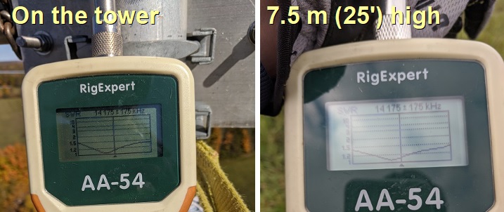
I did the coarse tuning with the yagi level at about 2.5 meters height, where the gamma match was easily accessible from a step ladder. I then lifted it higher and tilted it down for adjustment. At 7.5 meters height, a ladder is needed to reach the gamma match (6.5' or 2 m from end of the boom) when it is tilted down.

As expected, the element tap point was approximately correct. By fine tuning it, I achieved a 50 Ω match at about 14.150 MHz which, for this antenna, keeps the SWR below 1.5 across the band. The bulk of the improvement was in the value of gamma capacitor. 

The impedance became unreliable when the antenna elements were approximately parallel to the guys, despite being segmented into non-resonant lengths, and drifted when the reflector was tilted downward. The reliable readings were with the antenna level and the elements at right angles to the tower guys at either side.

After all the fussing the result was perfect. The antenna SWR curve matches the EZNEC (NEC2) design, and it barely budged after it was lifted onto the tower. Several hours were required to dismantle the rigging for lifting and lowering the yagi, and then to remake the coax connections and thoroughly weatherproof them. There was no moisture incursion or corrosion on any of the connections so the original weatherproofing performed well.

Of course I was eager to power up the stacks after I descended for the final time. They are working great. One of my tasks on the way down was to pull off the compensating L-network and delay line for the previously misadjusted gamma match. They are happily no longer needed. The extra RG213 patch cable will come in handy.

I'll close with a view at the antenna looking due north. There's a beautiful view of a lake and the fall colours from 40 meters up. But I have had little luck persuading others to climb up and enjoy the view. Maybe they suspect that it's a trick to get them to help with the tower work, and they may be right! It was a perfect warm and sunny fall day for completing the tower work. Colder weather is approaching.

CQ WW SSB is this weekend. I'll do it as a single op in a category that I have yet to pick. The station isn't ready for another multi-op. Perhaps for the CW weekend.

Thursday, October 17, 2024

Series Xc Antenna Tuning

Earlier this year I was helping a friend install and tune a 40 meter vertical that he had purchased at a flea market. It was made from large aluminum tubes of constant diameter and was therefore a fixed length (height). It was mechanically sound but required rope guys and a post for support.

He had prepared 16 radials of about 10 meters length -- about ¼λ -- which we stapled to the ground. It was directly fed with coax, without a matching network. The match was poor. The antenna resonated about 300 kHz too low, well outside the band. I suspected that the radials were too long, but cutting them was not an option.

Not being allowed to cut the radials or the vertical, there were still a few options. I studied the antenna with an analyzer for a few minutes to characterize its impedance. At resonance (outside the band) the impedance was approximately 37 Ω (I don't recall the exact value). This is typical for a vertical with low ground loss. However, as the frequency increased the R value also increased, along with the inductive reactance X. R was close to 50 Ω between 7.0 and 7.1 MHz (again, I forget the exact values).

This was a blessing and a curse. A blessing because only a series capacitor was needed to cancel the inductive reactance to provide a good SWR curve across most of the band, but a curse because I didn't have suitable capacitors on hand, fixed or variable. To my surprise, my friend had a large supply of ancient mica transmitting capacitors. All I needed to do was find the right one.

Rather than guess, we did the simple math to calculate the capacitor value that would equal the measured inductive reactance near the centre of the spectrum that of interest: 7.1 MHz. The value came to 400 pf. 

The equation, which all hams ought to know, is Xc = 1/(2πfC). Look carefully at that equation if you are unfamiliar with it: the smaller the capacitance, the greater the reactance. Large values that have a very low reactance (at the design frequency) can be found in lightning arresters and bias-T circuits to block DC while passing RF.

I rooted through the box until I found a capacitor that was suitable for 1000 watts and close to the desired value. That was a beefy 330 pf mica capacitor. I connected it in series and measured an excellent SWR curve. We made the connection more permanent and left my friend to add a weatherproof enclosure later. The antenna continues to work well.

This approach to antenna matching is similar to that for gamma matches where you find the tap point on the element where R is close to 50 Ω and then use a series capacitor to cancel the inductive reactance, resulting in a 50 + j0 Ω match at the selected centre of the operating bandwidth. There are other potential applications. 

Consider the SWR curves for two antennas resonant (X = 0) at 3600 kHz, for CW and digital modes. The vertical has a "perfect" ground, or one simulated with an extensive radial field, and the inverted vee is 30 meters above EZNEC medium ground.

Now suppose that you want to also have a low SWR for SSB high in the band, say 3900 kHz. You have several choices, and you can probably think of more:

  • Make it a fan dipole/vertical, with the parallel element tuned for higher in the band.
  • Cut the antenna for 3900 kHz and have a switchable coil at the base or partway along the element (each half-element of the inverted vee).
  • Switched L-network or similar to match the antenna at 3900 kHz.
  • Switched series capacitor to improve SWR in the SSB segment, if the R value is suitable.

Note that both antennas are not a perfect 50 Ω match for CW, though the SWR is close enough in most cases, especially when an antenna tuner is used. The vertical is more broadband than the inverted vee (or dipole), which is typical. Although the omni-directional mode of my 80 meter yagi (driven element as a simple vertical) has a reasonably low SWR up to 3800 kHz, I included a switched L-network to lower it further for SSB to "future proof" it in case I purchase a broadband solid state amplifier.

Getting back to those two example antennas, SWR curves are inadequate to determine whether it is possible to insert a series component to match the antenna for the SSB segment of 80 meters. We need to calculate or, better, measure R and X across the operating range. For reliable measurements you should use a modern single-port antenna analyzer or VNA of known accuracy, especially for large deviations from the nominal 50 + j0 Ω impedance. I use RigExpert but there are other excellent products on the market.

For this exercise I'll stick with calculations by EZNEC. Although I mostly used the NEC5 engine for the models in this article, NEC2 is perfectly good for these simple antennas, and it comes free with EZNEC. Below is a plot of the R and X values for both antenna models.

One striking difference is that the inverted vee's X (reactance) changes more rapidly with frequency. That's the reason for its narrower SWR bandwidth. Also, notice the slow change in R for both antennas, which increases with frequency. Finally, there is an excellent linear frequency relationship of both R and X. However, that is only true for small percentage frequency ranges. Other antenna types will have different curves.

The relationship scales: the chart is for 80 meters but the same is true for my friend's 40 meter antenna. It should be clear why I was inspired by the antenna feed point's measured R and X.

We can cancel the inductive reactance with a series capacitor to shift the SWR curve higher in the band. Of course it isn't quite that simple. First, since R will remain the same, that will determine the minimum SWR in a 50 Ω system. On the chart you can see that the vertical is more promising than the inverted vee. Second, the quality of the capacitor is critical. It must have a high Q so that very little power is dissipated by the devices ESR (equivalent series resistance) or it will fail with high power. Good transmitting capacitors (see the earlier article reference) should have a Q of at least 1000 so that the ESR is low enough for high power. Solve for R in Q = X / R and then use that in P = I²R to calculate the power dissipation. Unlike coils, capacitors are small so their construction and surface area to conduct heat away can be critical if the loss is more than a few watts.

For the vertical it is easy to find the correct capacitor value by calculation or trial and error in EZNEC. To bring X to zero at 3900 kHz the capacitor value is 835 pf. There are no commercial capacitors with that value so it would have to be done with a combination of capacitors or a variable capacitor, with or without a parallel fixed capacitor. EZNEC also helpfully calculates the power dissipation if you provide the ESR. For a capacitor with a Q of 1000 the calculated loss is almost exactly 1 watt for a transmitter power of 1000 watts.

We are not so lucky with the inverted vee due to that high R of about 94 Ω at 3900 kHz. This is a case where a two-component L-network is preferred in order to transform both R and X to achieve a better SWR. The same is true for an inverted vee tuned to resonance at 3900 kHz and brought down to 3600 kHz with coils.

It should also be noted that since the inverted vee is a balanced antenna, a series capacitor in each leg is required to preserve balance. In this case the capacitance reactance in each leg must be less because they are in series. That is achieved with a higher value capacitor of 550 pf versus about 280 pf if a single capacitor is used. You can use one capacitor but should not because the antenna becomes unbalanced and common mode current is more likely and a CMC choke with a higher impedance is needed to avoid excess heating.

At this point I'll reveal that I have an underlying motive other than what I've discussed. On my list for new projects is my longstanding desire to make my 80 meter 3-element wire yagi a yagi on SSB. It is only a yagi in the CW segment at present. A 4-square on 80 meters works from 3.5 to 3.8 MHz (the 80 meter segment of interest to me) while a yagi is too narrow band, only covering 3500 to 3650 kHz. Shifting the antenna upward 150 kHz would achieve my objective.

I won't get it done this year, so there is time to consider alternatives. A series capacitor in all 5 elements is one of the options. The approach has several advantages:

  • High efficiency: High Q capacitors are easier than high Q coils.
  • Small size: A capacitor and relay will fit inside the existing PVC electrical boxes.
  • Switching: SSB relay lines to the parasitic elements is already installed. The SSB selector line at present is only used to modify the L-network for the driven element in omni-directional mode.

Until now my plan was to place two coils in the parasitic element switch boxes. With the element tuned as a director for SSB, one coil would shift resonance downward to make it a reflector (as is currently done) and the second to move resonance downward from SSB to CW.

As a CW reflector there would be two series coils. That would further reduce the already low radiation resistance (due to the T-shaped parasitic wire elements) and incur loss in the coils. Getting coil Q high enough to avoid significant loss would require new enclosures to fit two of them in a manner that avoids stray coupling.

By using a series capacitor these difficulties can be largely circumvented. The new difficulty is finding enough of the needed low loss, high RF current capacitors of the required value. But first, let's determine the capacitor value and its performance using an EZNEC model.

For yagi operation from 3500 to about 3650 kHz the director is tuned to 3680 kHz and the reflector to 3450 kHz. By opening the shorting relay, the series coil shifts resonance downward by 230 kHz. For use between 3650 and 3800 kHz, the parasitic resonances shift 150 kHz upward to 3600 and 3830 kHz. 

The height of the driven element (tower + stinger) is difficult to adjust so an L-network tunes the antenna for yagi mode (all 4 directions) and for both CW and SSB omni-directional modes. In any case, feed point R is quite low for yagi mode and below 35 Ω in omni-directional mode.

My first question was how much the parasitic element's R would change when inserting the appropriate value of series capacitor at the feed point. For the required 150 kHz upward shift the capacitor value is 1400 pf. R increases from 21.4 Ω to 23.8 Ω, or about 10%. That's for perfect ground. When ground loss is added the percentage change is less since it is in series with the feed point. 

The percentage change is less when it is made a reflector by switching in the 2.1 μH coil. R is 23.9 Ω at 3450 kHz (CW) and 25.8 Ω at 3600 kHz (SSB).

That's promising since the impedance is roughly the same for parasitic elements tuned to either CW or SSB by the series capacitor. If the same can be done for the driven element, a fixed L-network can be used for all yagi and omni-directional modes. That can now be tested in the model.

I pulled out my old EZNEC model of the completed 80 meter yagi. There were several design iterations before construction began, and this is the one that was built. In the EZNEC view, the antenna direction is to the right.

I used NEC2 since NEC5 introduced small differences that I didn't want to spend time on even though the result is certainly more accurate due to the acute angle on one side of the T-shaped parasitic elements. Continuing with NEC2 does not substantially affect the present study. I'll switch to NEC5 when I am ready to proceed with the project.

The L-network for the yagi modes was refined to make the SWR curve as good as it can be. When I built the antenna, I used the model as a guide but built the matching networks based on measurements. The two were pretty close. 

SWR curves for CW were calculated and then 1400 pf series capacitors were inserted at the base of the 3 active elements (the inactive elements are floated) to, hopefully, shift the array to the SSB contesting part of the band, which is roughly 3650 to 3800 kHz. 

The driven element reactance is not the same as the reflector and director so I manually adjusted the capacitor until the SWR curves were roughly alike. The capacitor for the driven element is 3000 pf (less inductive reactance to cancel).

The curves are almost identical. I expected them to be close but not this close. The impedance change for the 150 kHz upward shift is quite modest so the same L-network at the driven element feed point works very well for both CW and SSB. 

However, we have not yet demonstrated that the yagi's performance is similar. I did that next.

To my eyes they're identical. In fact, the SSB performance is marginally better. Performance lags in the top 50 kHz for both CW and SSB, which was already known from the original design. Yagis, which are high Q antennas, are challenged on 80 meters where the percentage span of the operating range is high, in this case over 4%. That's equivalent to 300 kHz on 40 meters and 600 kHz on 20 meters.

The low gain is due to near field and far field ground loss, typical of verticals. It's worse with yagis since the radiation resistance is low. 4-squares perform better. I have plans to improve antenna performance, which I hope to implement next year. 

Series capacitors to support SSB appear to be a good technique to apply to the current and future version of the 80 meter yagi. It's simple, efficient (with the right capacitor) and predictable. All I have to do now is scrounge those 5 capacitors.