Sunday, September 30, 2018

80 Meter 3-element Vertical Yagi: First Light

Much to my surprise I have been making slow and steady progress on my 3-element vertical yagi for 80 meters. I have many projects competing for my attention. Although significant work remains to see this project to completion there is finally enough in place to give it a actual on the air test. It is time for an update.

When I last visited this antenna the central full size vertical was built, with enough radials (34, with 700 meters of wire) that it easily became my antenna of choice for DX on 80. During September I did the following:
  • Laid radials for the 4 parasitic elements.
  • Designed, built and installed the T-loaded wire elements.
  • Rough tuned the parasitic elements.
  • Hard wired the northeast element as a director and the southwest element as a reflector.
  • Put it on the air and compared it with the inverted vee.
Radials

A set of 8 radials for each parasite was laid down before the elements were raised. They are each 15 meters long except for the one that ties the radial hubs for the parasite and the driven element. In earlier articles I described my radial system topology as overlapping rather than connected at busses placed between the 5 elements in order to reduce the work of soldering radials to busses at the expense of more radial wire.

After the parasitic elements were installed the impedance was measured and the radials increased to 16. The impedance was again measured to determine the trend toward non-resonance in the radial system, which strongly depends on the ground's dielectric constant and thus the velocity factor.

The EZNEC medium ground model for 20 meter long radials is a very close fit to what I measured: ~40 kHz increase in resonant frequency when the radial count increased from 8 to 16. I can now adjust the elements confident that I can predict what will happen should I add more radials later. Apparently the velocity factor with on-ground and shallowly buried radials is substantially lower than in the model. This isn't surprising since it is difficult to accurately model radials of this type with NEC2. In part because they must be perched a fraction of a wavelength above ground, where less of the field flows through the ground.

Before proceeding with tuning I added 2 more radials to each parasitic element, for a total of 18. These are wires running the ~15 meters distance between each of the 4 parasitic element radial hubs. Although the change in impedance was negligible this should slightly reduce ground loss for the entire array, no matter the direction chosen, including the array's omni-directional mode.

I chose 15 meters as the radial length for two reasons: limit the overall area of the antenna to minimize the land taken from the haying operation, and; limit swings in parasite resonance as radials are added.

Parasitic wire elements

Designing the T-top wire elements was a challenge. This is an element topology that NEC2 is not able to model accurately. I knew this from the start, as I learned when I put up my 160 meter antenna last year. The second factor influencing resonance is the number and length of radials. The 8 radials in that antenna are 30 meters long, which is approximately the same as 15 meter radials on 80 meters, relative to wavelength. The resonant frequency is pulled downward.

For a single element antenna with a low feed point impedance the correction is as simple as an L-network. It doesn't matter that the antenna is not resonant since the network easily accommodates a non-zero reactance, and the efficiency is high if the resonant frequency isn't far off. For a yagi there is no forgiveness in tuning the elements; you must get it right.


As a guide I used the K3LR dimensions for a 160 meter version of this antenna which you'll find in ON4UN's Low-Band DXing book, version 5. With a bit of geometry and adjustment to fit the physical layout of my antenna I came up with dimensions for the T and the vertical. A little was then added to both to allow room to snip wire to reach resonance. The initial length of each leg of the T is 5.5 meters. The vertical is 12 meters, which includes an extra 0.5 meters for tuning purposes.

Two wire elements are visible in the photo above. Unfortunately you'll have to squint to see them. I didn't properly compensate for sag so the vertical segment drags on the ground. The centre junction is simply a stainless steel bolt which the wires wrap around and then snugged tight. It's lighter than an insulator and more secure than solder alone.

The ropes that form the top end of the catenaries for the wire elements were cut to length and installed when the stinger and top section were lifted. The elements were walked up the tower and connected and the bottom ropes tied to the anchors, located 25.5 meters from the tower. That's right at the edge of the radial system (10.5 meter element spacing plus 15 meter radial length) to minimize land use.

It took a couple of hours to adjust the tension of each rope to achieve the best compromise among element sag, force on the stinger and centering the stinger. Eventually I was done and ready to proceed to the next step: tuning the elements and lighting up the yagi.

Measure, measure, measure

As I said above, precision is of the utmost importance in getting a yagi working properly. To this end I was fastidious about measurements. A marked template was set up on the ground to ensure the wire for the 4 elements were cut to the exact same length. The wire elements are therefore identical. Exactly 3" of wire are wrapped around the insulator at each end of the T. When I tied the catenary ropes up the tower I made a mark on the tower where each T should terminate, which helped achieve symmetry. All element ground anchors are exactly the same distance from the tower.

Although opposite elements are, and must be 180° apart, adjacent elements are not 90° apart. This symmetry is necessary in a 4-square but not in the yagi. In yagi mode only two parasitic elements are in use. The other two are floated (disconnected from ground) making them non-resonant and effectively invisible. I used this feature to optimize array aiming for my geographic location. Floating works, as demonstrated by no change to driven element impedance when the parasitic elements were raised and left floating.

The feed point of each wire element is similarly identical with respect to radial hub and its support, switching system anchor, back plate and enclosure. Before tuning the elements I measured the resonant frequency of all 4 of them, once with 8 radials and again with 16 radials.

The resonant frequency was below the design objective of 3.680 MHz so that they can be cut to resonance. More important is that my fastidiousness resulted in a resonance spread among the 4 elements of only 20 kHz, or 0.6%. Notice that the resistance part of the impedance dropped 7 Ω with 16 radials. There is obviously more ground loss to be eliminated. I can probably bring the resistance closer to 20 Ω by doubling the radials. But that's another 1,000 meters of wire! Efficiency doesn't come easy.


To measure any element of the array, including the driven element (tower), all other elements must be floated. That is, the monopole and radial systems must be disconnected. Otherwise the mutual impedance will mask what is really going on. One of the jobs of the switching system will be to float elements that are neither directors nor reflectors for the selected direction. All parasitic elements are floated when the array is in its omni-directional mode.

Rough wiring the 3-element yagi

The next step is the fun part: lighting up the yagi. Since the most useful DX heading is towards Europe I rough wired the northeast element as a director and the southwest element as a reflector. Since I don't want to cut wire at this time I calculated the amount to shorten the element to resonate the director to 3.680 MHz and shaved the insulation of the wire at the appropriate position to expose a tap point. The ~40 cm of wire beyond the connection has negligible effect on element behaviour.


For the reflector I used a rough wound coil of AWG 14 wire from my junk box since it looked to be about the right size. I attached it and alternately squeezed and stretched the coil until it resonated at 3.450 MHz. This only took 30 seconds since the analyzer continuously recalculates the impedance. All I had to do was move my hands out of the way after each adjustment.

With the element tuned I temporarily completed the connections with wire nuts. I move the analyzer to the driven element and measured the impedance of my improvised 3-element yagi at 25 kHz intervals.

The resistance part of the impedance is about as expected. This clearly shows how important it is to achieve the lowest possible ground loss with the biggest radial system you can manage. Even with a ground loss as low as 5 Ω the loss can be -2 db. That's a lot.

The X value is not terribly important, provided its absolute value is not much higher than R. That helps to minimize matching network loss. However for now I am leaving the 4:1 SWR as is and correcting it with the rig's ATU. The estimated total transmission line loss is -2 db despite being almost 300' long. It isn't difficult to keep transmission line loss low at 3.5 MHz. Once the matching network is in place the loss should be better than -1 db.

Before going further it is worth a moment to talk about instrumentation. To achieve accurate and repeatable measurements it is important to have an analyzer with the requisite performance and to use it properly. The RigExpert AA-54 is quite good considering the price. There are better products on the market for a higher price.

I am not making any recommendation. Refer to detailed technical reviews such as those found in QST rather than rely on informal opinions of friends who may know even less than you.

The analyzer should be able to get the R and X values correct within a few ohms when the SWR is high, which most of the cheapest units cannot do. Not only is accuracy important but so is repeatability. That is, the values should be the same between readings, including readings made after the unit is turned off for a while and reconnected to the antenna under test.

Make sure your body is not influencing the measurement by moving around. Do the same for the analyzer itself, including when in your hand or supported elsewhere. Keep the test leads short or compensate for the length; better units can calibrate on the transmission line length, or use software such as TLW to convert the measured impedance to that present at the load.

Doing it right with a finicky antenna like this one can save you a lot of grief. Buy the best analyzer you can afford if you like experimenting with antennas. A 2-port VNA is favoured by those with a need to design and test more complex antennas or to analyze impedance transformation networks. A handheld unit like the RigExpert is perfect for me.

On the air

This article is being written after 3 evenings with the antenna in its hard wired direction to the northeast (Europe, North Africa and Indian Ocean). Not only has activity on 80 meters has perked up after the summertime lull there are several current DXpeditions roughly in that direction, including 9X0T and TO6OK. As always there are many Europeans active overnight and their sunrise.

When I first lit it up I was briefly disappointed. Switching from the inverted vee (now with an apex of 19 meters) to the vertical yagi the band noise dropped precipitously. It seemed that the antenna efficiency was low, so that the analyzer measurement might be hiding a deeper problem. Or, perhaps, the transmission line loss is higher than calculated. My worries dissipated when I tuned in a signal from Europe.

All European signals were stronger versus the inverted vee just as they were when the antenna was configured as an omni-directional vertical. But now the difference is substantially greater. I did extensive comparisons to ensure that Faraday rotation and other causes of QSB were accounted for by comparing through signal strength peaks and valleys. The improvement was consistent. However there is variation with different stations and path lengths. The variation -- elevation angle, polarization and skew -- demonstrates the value of having more than one antenna per band.

Signal differences were as little as 1 S-unit and as much as 4 to 5 S-units. That is promising. But what happened to the band noise? One hint was listening to W8 and W5 stations off the back of the yagi. The F/B is very good. Signals that were S-9 on the inverted vee would drop to S-3 or lower; as a vertical the difference was typically 2 S-units in favour of the inverted vee. What these differences are in decibels is hazardous to estimate since an S-meter is not a reliable instrument.

What appears to be happening is the attenuation of early fall atmospheric QRN from warmer locales south and southwest of VE3. The northern path to Europe is of course colder with less of the weather that contributes to noise. That is, the antenna has good directivity. I confirmed this by comparing reception against my 175 meter long northeast Beverage. The Beverage is still the better receive antenna, though by far less than with an omni-directional antenna.

Keep in mind that a well tuned 4-square can achieve similar or better F/B over a wider bandwidth than this yagi. I knew this before proceeding with this antenna. For me the ability to experiment and make a less expensive directive array of similar performance was a deciding factor.
I can see myself living with the yagi on 80 meters and reserving the Beverage and other planned receive antennas primarily for use on 160 meters. I have no plans for a directive transmit array for 160 meters, although that could change.

Up next

The switching units must now be assembled, installed and adjusted. The 4 parasitic element units must be identical to ensure identical performance, which is important when switching direction. This applies to the coils, relays, lengths and routing of internal wires. The unit at the driven element will contain the switching matrix, signal distribution and relays for the matching networks.

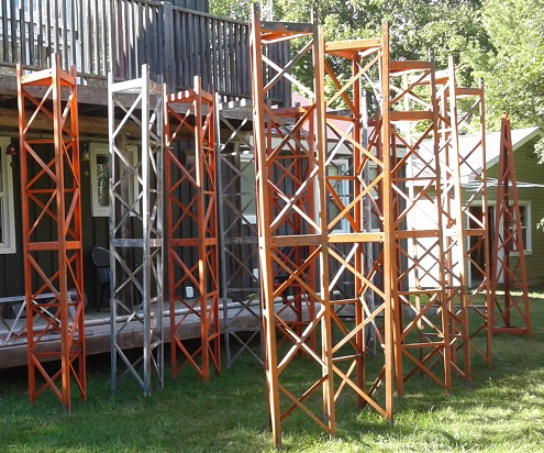
QRP friends visiting the 80 meter array (Credit: VA3RKM)
Most of this work can be done indoors. The only parts I have yet to order are the relays, which I have been researching. There are trade offs with respect to cost, power handling, RF isolation and current draw. A wrong choice is not a disaster since they are easy enough to access and replace. The switching matrix is built but not fully tested.

The driven element stinger may need to be replaced, if not this fall then next year. It is proving to be mechanically marginal when tension is put on the catenaries. I would like to take up more of the slack. Replacement would take a few hours and should only affect the L-network due to a change in the electrical length of the driven element.

I don't anticipate completion before November. There are too many other projects to be done this fall and this job can be done during the cold weather. I may even lay more radials before the snow flies.

With the rough wired yagi performing so well I am really looking forward to completing this project.

Friday, September 21, 2018

Useless Stuff

As a ham for over 45 years it is perhaps unsurprising that I have a large junk box. It's not really a box but rather dozens of boxes and piles of equipment and parts spread all over the place: basement, shack, garage and lurking among the trees. Some is little different than pure junk while others are fully functional though dated or with no foreseeable application.

Very little of my junk disappeared during the 20 years I was out of the hobby, or before or since for that matter. Since returning 5 years ago I have collected even more. Far more Storing, categorizing and finding stuff has been difficult. Not a week goes by that I don't find something interesting or valuable that I forgot that I had or didn't realize that I had it at all.

With that said I will now present a select set of junk that may induce nostalgia, bewilderment, "hey, I need one of those!" or violent disagreement over what, in fact, is junk or whether it can possibly have any use.

Heil headset

I purchased this headset over 30 years ago and I loved it. I still do. It's light, comfortable, and has a high talk power mic element.When the microphone cable became intermittent a few years ago and the ear pads deteriorated it was retired in favour of a modern headset. Here are the reasons:
  • Modern rigs have equalizers. A special "talk power" mic element is redundant. It is better to adjust the rig equalization once and then use any mic with a flat response.
  • The mic element is dynamic. It can't easily be connected to a PC and some rigs only support high output electrets. Again, it is better in today's contesting shacks to stick with electret.
  • Good quality PC gaming or VoIP headsets are inexpensive. Ham specific headsets are no longer necessary.
  • I like open air ear pads despite not attenuating ambient sound. When I start doing multi-op contests from my station they will present a problem.
FT-102

When I bought this rig (used) in 1985 it was fabulous. The receiver was quiet and performed very well in comparison to competitors. It has a bit of a cult following. Unfortunately it does not work, suffering as it does from a pernicious design flaw: short life relays throughout.

Many have replaced the relays and continue the rig it to this day. But its time has passed. The transmitters are tubes that must be periodically replaced and frequency changes require manual transmitter tuning. The rig is not PC friendly, although there are ways to do it if you insist. Receiver performance is not comparable to the best modern rigs.

I can't bear parting with it and I also won't waste time fixing it. So it sits on a shelf. Behind it is a another useless item: a home brew power supply I built 30 years ago for a kilowatt 2 meter amplifier. The power supply works, the amplifier was never built and never will be built.

Magazines

I have come to despise paper. Whether it be logs, QSLs, newspapers, books or magazines. In this way I am quite modern. Before I moved from Ottawa 2 years ago I discarded over 40 years worth of ham radio magazines, catalogues, hamfest material and much more. Other than one big bundle of QSTs that I gave away to an interested ham it all got recycled. Well, except for one old issue of QST that had my picture in it.

If I need to look up an old article it is almost always accessible online. Most magazines I now get are electronic. Publishers that will insist on sending me paper magazines are magazines that I no longer subscribe to. Really, most of the subscription price is printing and postage, and the postage can be quite dear when sent from other countries. They are no longer worth the trouble, time or money.

I have a life ARRL membership so the QSTs keep coming, and they are once more accumulating. Before long I will once more be feeding the recycler.

Scrap hardware

When you have a fastener, clamp, clip or other bit of hardware is bent, rusted or of indefinite function what do you do with it. Provided it is somewhat usable I toss it into a box with similar stuff, roughly sorted by type. The rest goes into the garbage. I have even scooped up such stuff that other hams are discarding. I must have 100 lb or more of this scrap hardware.

I do this because of the many times I encounter an odd situation where I need an odd bit of hardware to accomplish a task but I don't want to waste or buy a new one. For example, old and rusty muffler clamps are used to jam a tube or pipe, or a perplexing plate with scattered holes in it becomes a shim or clamp washer, or a few old hose clamps are connected end to end lash a pipe to a tree or tower leg.

All of this scrap is stored outside or in the garage where there is lots of room and I don't care if it corrodes further. I often toss the stuff beyond the pale into the garbage bag when I root around for something useful.

Tuner

Flip through any ham magazine and you'll find many pages of advertisements for antenna tuners of all types and sizes. They can come in handy and for many hams with limited space they may be the only practical way to get on the air with whatever they are able to put up for an antenna. Tuners have occasionally found a use in my station over the years.

However tuners have their limits. While you may be able to transform most anything to 50 Ω it may be at the expense of efficiency. The cost can be exceptionally high, especially with short antennas on the low bands. As a contester I have additional concerns when it comes to tuning antennas since doing so costs valuable time even when the tuning is largely automatic.

Despite these qualms I still hold on to my tuners, large and small. Although I don't want to ever use one again I can't shake the feeling that one day in a pinch -- an antenna blows down in January when a rare DXpedition appears -- I absolutely have to have one.

Guy wire

I have a lot of guy wire. I have far more than I need or can ever hope to use. Most of it is used but is in excellent condition, whether from others hams or commercial surplus. Quite a lot of it I got for free.

The large quantity of guy wire in the picture is, unfortunately, truly useless except in the station of a truly extreme ham. I am unlikely to use it. The reason is that it is ⅜" EHS. That's heavier than you'd need on a big tower with stacked 40 meter yagis!

The reason it's useless is that guy wire must be tensioned to ~10% of breaking strength if it is to be taut enough to prevent excess tower motion or bending when the big winds hit. For this cable the breaking strength is 16,000 lb, so the pre-load tension is 1,600 lb. At each guy station on the tower that's 4,800 lb of force trying to tear the tower apart. There aren't many towers used by hams that are designed to withstand that radial and axial load.

On the other hand, well, you never know. Perhaps I'll find a use for it.

Rotator

This AR22 light duty rotator turned a Moseley TA-33jr on my first tower, back in the 1970s. For a television antenna rotator it struggled with a small tri-band yagi. Whenever the wind blew over about 60 kph (very common out on the VE4 prairie) the antenna spun and the rotator had to be recalibrated. But it was certainly inexpensive, perfect for a budding contester.

In addition to its low capacity it wasn't very robust. The controller's pulse-driven direction indicator uses a cheap electro-mechanical ratchet made of plastic and a spring that doesn't work well. It's one great feature is that you crank the dial to the desired direction, whereupon it starts up, turns, and shuts down when done. A harbinger of things to come in later years.

40 meter wire yagi

This antenna is proof that I have used low band wire yagis in the past, and that I not only design and write about them on this blog. This is a 2-element reversible inverted vee yagi I put up 30 years ago. The box contains the relays for the switching unit.

To simplify the antenna the driven element is fixed and the parasitic element is switched to be either a director or reflector. Well, this was 30 years ago and I didn't yet have a MiniNEC tool, nor did I appreciate the problems with this arrangement. When I fired it up I quickly learned why. The version you'll find on this blog is a far better design.

Despite its design problems it worked quite well. Although it'll never go up again I enjoy the memories whenever I come across it while I'm rooting through boxes looking for something.

Heliax connectors

I have been fortunate to find sources of used Heliax connectors at very good prices. They come available when commercial systems are decommissioned or the cables replaced. Among a bunch of connectors me and my hacksaw liberated last year were a couple of UHF female connectors for ⅞" Heliax. Those are rare and I was pleased with my good fortune. That changed when I got home and opened them up.

They are older than I realized. These connectors only fit the cable series that predates the LDF series. Connectors for the two series are not compatible since the older cable outer conductor has spiral corrugations while the LDF and AVA series have concentric corrugations. That's a shame.

Unfortunately the connectors have little use now because the ancient cable they are made for is rarely still in service. For now I can only admire them.

More obsolete equipment

Two years ago I made an effort, mostly successful, to clear out some useless stuff cluttering my basement by taking a table at a local flea market. The pictured items did not sell. I was not surprised. Despite working perfectly well they have little use today.

Packet radio is certainly around, though perhaps not so much at the data rates the PK-88 supports. The interest it received was no more than smiles for the memories it provoked. The high power low pass TVI filter has little purpose now that over-the-air (OTA) television reception is a rarity. It's good that TVI due to HF harmonics has been relegated to history, but then so is the TVI filter. It didn't get a second glance at the flea market. Both went back to the basement.

So much more

This sampling just scratches the surface. I didn't show my stock of ancient TTL logic chips and op amps, metal stock, short lengths of wire and rope, transformers, and so on. I suspect most of it will stay in boxes until after I'm gone when they'll finally go to the landfill. Indeed, that is also the likely fate of my towers and antennas if current trends in our hobby continue.

I do not keep the perpetually useless stuff for nostalgia or because I favour older generations of technology. I favour the march of technology, and that is what I aim for in my station. I will not buy and restore boat anchors, not even if I fondly look back on those products from my early days in the hobby. Others love doing that and I applaud their enthusiasm. But I won't even buy a paper book or magazine anymore.

Do I sell this stuff? Most of it has no value. Do I give it away? Most hams are in the same situation, having junk that they'll never use or need. Throw it out? I admit that it's hard to let go of stuff that maybe, just maybe will find a purpose someday. Part of my problem is that out here in the great emptiness I have far too much room to store the useless stuff hams tend to accumulate. So on it goes.

Monday, September 17, 2018

Challenges of Long Boom Yagis

The very biggest of the big guns put up large yagis for all the HF bands and then stack them for additional gain. This is neither easy nor inexpensive. To do it you either have money to spare or an especially strong motivation to pursue a few extra decibels. There is no one right answer. For someone like me, aiming high but not crazy high, trade-offs are necessary.


The above diagram from W2PV's Yagi Antenna Design is one I've shown before on this blog. It should be obvious that achieving an additional 3 db of gain by increasing boom length alone is exceedingly difficult on HF. Consider that a 1λ boom on 20 meters is almost 21 meters long (70'). Even at half that length on 10 meters it is still a giant. Hence stacking.

A long boom on HF yagis is rarely longer than 48' (14.7 meters). There are longer boom yagis out there, and even commercial products, but as I said they're rare. Given the incremental performance they are, in the opinion of many, not worth it. Consider that a 48' boom with a 3" diameter has a projected wind area of 12 ft². Treating it as a cylinder the wind load when broadside to a 135 kph (85 mph) wind is 240 lb. On 20 meters and up a long boom yagi has its maximum wind load in this orientation.

Building a long boom yagi to survive these and higher winds is expensive. The antenna will be very heavy to lift. The rotator and tower must be rated to deal with the load. Required boom strength increases faster than linearly with boom length due to the bending stress from the added wind load, its length and its weight. I need to keep the weight reasonable enough to allow tramming the antennas up the tower so that I can avoid the expense and land access issues of a large crane.

Since the gain of a 20 meter yagi with a 40' (12 meters) boom is only ~1 db lower than its 48' long bigger sibling I have chosen this length for my planned yagis. On 15 meters I am going shorter still: 32' (10 meters). For the next year or two, for the duration of the solar cycle minimum I will not be building long boom yagis for 10 meters. Should I decide to build 3-element yagi on 40 meters it will also use a 40' boom.

All of these antennas have been modelled and compared to longer and shorter boom yagis. The one for 15 meters was described in this blog quite some time ago. The 20 meter yagi is similar to the 5-element 40' boom yagi described in the ARRL Antenna Book. The 40 meter yagi is of my own design, both 3-element and with a coupled resonator for broadband low SWR. The latter antennas I will likely describe in a future article once the madness of tower and antenna building season subsides.


Few hams use yagis with booms longer than 6 to 8 meters and even these look big close up. The longer ones don't look so big when they're high in the air. On the ground you can better appreciate their size. In the picture you can see the first two long booms I built earlier this summer. Each is 3" diameter. The short one is 32', for the 15 meter yagi. The longer one is 41', for the 20 meter yagi. The garage they're in front of is 26' (8 meters) wide.


Both yagis come from 3" tubing I acquired a few years ago, with a heavy wall pipe inserted into the centre of the 40' boom. I took the pipe to a machine shop where they used a metal lathe to turn down the ends to fit within the 3" tubes. They did a very neat job and it was inexpensive. I mated the boom sections with the tools in my own workshop. The completed booms were set aside while I focussed on other projects.

Neither of these booms is sufficiently robust to be mounted high and rotated. I base this on calculation with software tools. The data say they can do the job, though without a margin for ultimate safety that I consider sufficient.

Instead these two yagis will be side-mounted, fixed on Europe and stacked with electrically identical yagis rotated at the top of the tower. The booms for the top yagis will be stronger, using aluminum I have on hand plus heavy wall tubing I will purchase. I am awaiting quotes on the element tubing (0.058" for telescoping) since of the many aluminum suppliers within driving distance none stocks this wall size. I have already bought the aluminum bar from which I will fabricate element-to-boom clamps.

None of this is cheap! That said, it is more economical than buying commercial products and I learn a lot along the way. The real cost is that it takes time. I may not get as far along as I'd like before winter with this and other projects. But it's fun, and that's as it should be. For 40 meters I would like to experiment with element design by building one and mounting it for use as a dipole during the winter and spring. This will help me assess its survivability before proceeding with yagi construction.

Long boom HF yagis have one other irritating feature: tuning. Unlike most 3 and 4 element yagis the driven element on a longer yagi is far from the centre. You cannot reach the driven element from the tower to adjust matching. For my 5-element 20 meter yagi on a 40' boom the distance between feed point and boom centre is 13' (4 meters).

Most commercial yagis tell you exactly what measurements to use, but on a home brew antenna a substantial amount of adjustment may be necessary. My plan is to mount each yagi vertically on a suitable tower (one without any antennas that can interact with the yagi) for tuning.

When I am done I will have one tall tower (the present one) dedicated to 40 and 10 meters and one dedicated to 20 and 15 meters. This is common practice for many contesters. One or two of my tri-band yagis will be fixed or rotatable to fill coverage gaps, especially for higher elevation angles to the Caribbean, the US and other paths when needed. Full implementation will take me into 2019.

Speaking of which, look at what showed up last week.


This is the tower for 20 and 15 meters. If all goes well it will be planted in the ground by early October. With luck and hard work it will be raised before winter. Assembly of the yagis will be done concurrently. Unfortunately I only anticipate raising the two side mounted yagis this year, with the rotatable antennas delayed to 2019. The weather will soon turn against me.

Sunday, September 9, 2018

Chain Drive Prop Pitch Rotator

Even if you never lay eyes on a prop pitch motor and would never dream of or need a rotator of its capability it can teach lessons useful to many hams. I first saw a prop pitch motor up close and in action almost 35 years ago yet did not have one operating in my own station until last year. For what it's currently turning it is not strictly required but I expect that to change.

In this article I'll describe my prop pitch rotator system. I claim no credit for its design or construction since I purchased it secondhand. My job was to understand its mechanical and electrical details, then install and adjust it. I quite like it in all its "retro" awesomeness. I did have to design and build a direction indicator attachment to work with the home brew controller because most of it was missing.

While many hams who use a prop pitch motor opt for a simpler rotator system this one has several notable advantages. There are many ways to turn one of these beasts into a rotator.

Outboard mount

Use of a chain drive allows the motor to be installed with the shaft pointing down. This is advisable for unmodified prop pitch motors since the original gearbox lubrication is oil which can foul the electric motor and leave the gears dry when mounted with the shaft pointing upward under the mast. Replacing the oil with grease is strongly recommended for these reasons and because the oil will have dried or seeped out over the decades. The newest prop pitch motor was manufactured over 50 years ago!

With the shaft pointing down it is necessary to couple the motor shaft to the mast using a more elaborate system. Refer to the adjacent picture as I describe the system. For other pictures you'll be directed to follow the links to previous articles.


Unlike the typical rotator designed for amateur radio use a prop pitch motor is not designed to support the weight of a large mast and antenna system. When it is mounted under the mast it is mandatory to use a thrust bearing to support that weight. That leaves the motor to solely deal with torque, a job at which it is supremely capable.

It is not enough to simply wrap a chain around the mast and motor shaft. That would place an enormous radial load on the motor shaft which it cannot handle. A feature of the outboard mount is the elimination of these forces from being transferred to the motor.

Hanging beneath the top shelf (more detail on this will be shown below) is a mechanically robust open box that places a thrust bearing (for radial loads) above and below the gear that drives the chain. The bearings transfer the radial force to the tower and remove bending force from the motor shaft. The platform also supports the dead weight of the motor sitting on top.

The drive shaft in the tower has a similar arrangement with a bearing below the chain drive and another at the top of the shaft; the mast couples to the top of the drive shaft. I use this terminology to distinguish the mast (rotating antenna support) and drive shaft (part of the chain drive), although both can be though of as part of the mast.

The bearing under the drive shaft supports the full dead weight of itself, the mast and the antennas. It is a deep groove bearing designed for both axial and radial loads.

The collar on the drive shaft contains the cog gear for the chain and sits on top of the bearing. The drive shaft extends below the collar through the bearing for lateral support. See the article on mast construction for pictures.

All bearings are sealed. This is absolutely necessary since they won't last long in the weather without this feature. Additional weather covers are not required but can be helpful since sealing is never perfect and we want the bearings to last outdoors for many years of trouble-free service.

The photo shows the outboard mount from below, complete with an early version of the direction indicator subsystem. It gives a better idea of how massive and rigid it is. The system with its support struts weighs more than I do! That's without the motor attached. All the metal plate is ¼" galvanized steel. Joins are welded or made of ¼" angle stock. The top plate has an opening for the crown gear to mate with the prop pitch motor.

Chain system

The chain drive is quite simple. Standard size gears are welded to the motor shaft and the drive shaft and wrapped with a #60 (1") chain. The chain is stainless steel, and is highly recommended since access is limited for regular oiling. It's totally exposed to the elements. The rust you see in the pictures dripped from elsewhere. I cleaned and repainted the gears and other steel components that are not galvanized.

The number of links in the chain is adjustable. The chain has a master link. Without a master link a pin tool is needed to open and close the chain. A master link is the easier system to use. I did not need to change the number of links since my tower is the same as the previous owner's.

To avoid mishaps with the master link clips on top of the tower I raised and installed the chain with it wrapped around the motor shaft. When the drive shaft was dropped into place the chain was left loose around the bottom bearing. Only then did I wrap the chain onto the gears.

In the top picture you can see a ½" threaded rod on the bracket at the top of the platform. That and slots in the bracket are used to adjust the distance between the platform and the tower. Chain tension is determined by the distance.

I levered the chain onto the gears bicycle derailleur style after moving the platform inward as close as possible. It was then moved outward until the chain was taut. Looseness in the chain results in unwanted play in the mast that allows the wind to push the antennas back and forth several degrees. When properly adjusted the entire massive system can be easily spun by hand. When the motor is bolted on manual rotation is impossible.


Vertical alignment was a challenge. There is little room to adjust the vertical position of the motor platform. My first attempt resulted in chain binding on the drive shaft gear (see above). The only adjustment is the tower leg pinch clamp. Since there are no slots for the bolts on the platform's vertical struts the adjustment range is narrow. With some effort I was able to push the top of the platform down enough to allow the chain to move freely on the gears.

Control unit

The control unit is home brew, and although it shows its age it works well. Eventually I would like to replace it with software driven unit and only use the 24 VDC power supply to power the motor. My objective is a small desktop controller head, or eliminate it entirely with a PC application For the next year the project will remain low on my priority list.


The meter is obviously scrounged from an old CDR (now Hy-Gain/MFJ) rotator. There is an op amp circuit powered by +12 and -12 VDC that requires a linear potentiometer coupled to one of the rotating elements up the tower. The op amp circuit has two calibration pots: one to centre the meter and another to set the circuit's gain (degrees of rotation per ohm). Their settings are determined by the pot on the tower. The advantage is that almost any linear pot can be used. Mine is a multi-turn pot, identical to the one used by the previous owner, so that setup is not critical and allows > 360° of rotation. But don't try it unless the coax rotation loops are suitably designed.

I use Cat5 cable for the run up to the pot and 10/3 electrical cable to the motor. Except for part of the pot wiring both are burial grade and UV resistant.

Direction indicator

Of the two most common methods for sending direction data from the rotator to the control unit -- motor pulse generator and potentiometer -- a pot is the simpler method and will work with a greater variety of commercial control units. On the other hand a pulse generator has better long term reliability. A third method I learned about is a processor-based compass module to send direction data over wireless to a ground-based receiver.

I chose a pot since it's simple and my current control unit requires it. The first system I built (seen in an earlier picture) didn't survive long. First the wiring broke and later the ancient pot failed. The poor weatherproofing I hoped would last the winter didn't. But it was December, it was windy and cold on the tower, so I took my chances.

These 10K 10-turn linear pots are not cheap. Instead I ordered several from overseas at 10% the price. The downside was the long wait for the slow boat to arrive from China. When they arrived in August I got to work. This time I took the opportunity to improve the unit. After a couple of weeks in service it continues to work well. We'll have to wait and see how it does over the long term.


Some detail can be better seen in the earlier picture so refer to that as necessary. I chose the drive shaft to turn the pot. Common hardware store perforated steel strap holds the unit and has plenty of holes for attachment to the motor platform, bolt on the pot and tie the wires. The drive shaft coupling is made from strips of aluminum flashing (~0.03") and a hose clamp, with a ¼" screw to couple to the pot shaft.

The flashing was chosen so that perfect alignment between the drive shaft and pot is unnecessary. It will flex as the shaft turns. Silicone caulk keeps water out of the shaft coupler. Below that is a 1" circular plastic rain/snow shield cut from a food container and drilled at 15/64" to fit tight on the pot shaft. The shaft opening to the pot is coated with dielectric grease and the nut and lockwasher are caulked. The enclosure for the pot may look familiar: it's a cap from an empty WD-40 spray can.

The wiring tail is connected to the main cable run with crimp connectors. There are weatherproof commercial connectors available but this is easier to install and the wires can be cut and re-crimped easily. I enjoy the challenge of improvising with commonly available materials.

Lifting

Due to the weight and awkward dimensions of the motor platform I had to resort to alternative rigging. When all the tower sections were up the only parts of the platform installed were the support struts. These had to be installed during tower construction because they attach to two tower legs at the splice at the bottom of the top section. Once the top guys are tensioned those 4 bolts cannot be touched.

A heavy gauge steel strut was extended outward from the girt at the middle of the top section, which is several feet above the struts. The gin pole pulley was transferred to the lifting strut and the end of the strut was cable stayed. The rigging was tested to ensure it would support the load.

Using this rigging the bulky platform was lifted without being scraped along the side of the tower and tangling in the lower 3 sets of guys. The lifting strut swings laterally to help with levering the heavy platform around and onto the top surfaces of the support struts.

Despite the special rigging there was some difficulty maneuvering the platform into position. It required adjusting my safety restraints so that I could lean outward from the tower and apply the required muscle.

Once in position I secured the top of the platform to the tower legs with the pinch clamp. During motor installation, chain adjustment and electrical work the platform served as a handy shelf for tools and parts.

Spare motor

I was fortunate to be given a second working prop pitch motor when I purchased the system described in this article. My dilemma is whether to keep it as a spare or to custom build a clone of the motor platform for the second LR20 tower I am planning to raise.

Spare prop pitch & drive shaft (right) posing with a Ham motor
The platform design makes it convenient to replace the motor. You remove the 6 bolts holding the motor to the platform and drop in the substitute. The chain must be tied when no motor is present to prevent the mast from freewheeling.

Wire splices between the motor tail and the main run are silicone-filled wire nuts designed for outdoor use. They are inexpensive and easy to use, and can be reused at least once if you are careful. You can see the nuts in the picture at the top of this article, before a weather cover was installed.

Building a platform for the second tower will require the services of a machine shop since I do not have the tools needed. Material, manufacture and galvanizing could be very expensive. I would also need to acquire a third prop pitch motor as a spare to ensure minimal disruption when a motor requires service.

A modern, high-capacity rotator may be the better choice. It will certainly work out cheaper. The decision can be put off for only a couple of months.