Tuesday, June 28, 2022

10 Meter Stack Switch

This is the final stack switch for my 5/5 stacks on 20, 15 and 10 meters. The 10 meter yagis were built and raised last year, but without the stack switch only the upper yagi was connected. Once I make and install the phasing harness and control cable the system will be complete. Of the three stacks, this one was the lowest priority because of the solar flux. Now that cycle 25 is blossoming, I want the stack fully operational for the fall contests.

The design of the stack switch is almost identical to that for the 20 meter and 15 meter stacks. In this article I will focus on the differences. Please refer to the earlier articles, and this one about L-network stack switches. In addition to construction and testing details, you will find the theory of operation, component selection and a circuit diagram.

The major differences from the other stack switches include:

  • More compact L-network to reduce stray inductance
  • Compensation for the internal wiring when using the upper or lower yagi
  • Components are mounted on the enclosure cover

The "dead bug" construction method used is not ideal for preserving a constant impedance throughout the circuit. A better method is to mount them on a circuit board and place the traces to approximate a transmission line between major components. It can never be perfect since wires travel to and from the board and there are uncompensated paths through the relays. 

Impedance deviations are small on the 20 meter stack switch, and imperfect but still acceptable on the 15 meter stack switch. I knew I would not be so lucky on 10 meters. The problem of stray reactance in inverse proportion to the wavelength; the reactance of an inductor is proportional to the frequency. Wire is an inductor, whether in a coil, as component leads or for circuit connections.

Before diving into those challenges, it makes sense to start with the final item: mounting components on the enclosure cover. My motivation to try this method of construction is due to Steve VE6WZ. He has several videos on his YouTube channel describing its advantages. It does indeed make working on a circuit easier. I'll definitely consider it for future projects.

Referring to the earlier articles you'll find that I'm using an identical set of components. They fit neatly on the aluminum cover. All I had to do was position the top connectors around the protrusions for the enclosure's screw holes. The aluminum enclosure is from the Hammond 1590 product line.

I'm using the same layout as for the 15 meter stack switch since it has less stray inductance than the layout used in the 20 meter unit. As we'll see, the wiring is be the same but mounting of the L-network will be quite differentl The terminal strip I used in the other stack switches is not needed. I hadn't yet made that decision when the picture was taken, which is why it's there. 

The 100 pf ceramic capacitor I purchased for a few dollars in the Hamvention flea market last month is suitable for a kilowatt in this application. It's worth mentioning that there are no extreme voltages and currents in a L-network with a low transformation ratio (2:1) and a modest SWR at the edges of the yagis' frequency range.

The picture at right shows the stack switch fully wired. Unlike the ones for the lower bands, the L-network is built over its relays for the shortest possible lead lengths. The lead lengths to and through the relays to the yagi ports at the top are about the same as the other units. The compact layout is made possible by the small capacitor and coil. 

TLW was used to design the network. While this network works well as a single band stack switch I must empathize that it is not a narrow band device. That is a common belief going by the feedback I've received from readers and others. A (transmission line) broadband transformer certainly has its uses, such as for tri-band yagi stacks, but it is larger, more difficult to build and in most situations it will be less efficient. The L-network single-band design works well and it is easy to design and build.

I did not adjust the default coil Q in the TLW design. The actual coil Q is calculated at over 300 using K6STI's Coil app. Power dissipation is lower than the calculated value in inverse proportion to the Q. For example, the loss would be 6 watts for a Q of 300. The coil is wound from 12 AWG copper. I tried 10 gauge wire but it was so stiff that I was concerned about damaging the circuit during mounting and network adjustment. I made a temporary coil wound with thin wire for the initial bench test since it was easy to work with.

Stranded wire connects the two ends of the coil to the relay pins to relieve mechanical stress on the relays during installation and adjustment. The standoff and aluminum angle bracket on the capacitor's cold side have sufficient mechanical strength to rigidly support both the coil and the capacitor.


The VNA plot of the completed stack switch in BIP mode (both in phase) shows a remarkably good match and low insertion loss. The insertion loss is not perfectly accurate because the impedances to the yagi ports are not exactly equal and the VNA was not recalibrated for this measurement. When I reverse the loads on the yagi ports the measurement is lower. We want the average insertion loss through the two yagis ports as close to -3.01 db as possible to minimize heat dissipation. With properly selected capacitors almost all the loss is from the coil.

There is one extra component in the stack switch that you may have noticed: a capacitor at the top of the unit. This brings us to a discussion about impedance compensation.

Due to the dead bug design there is an impedance"bump" between the input port and the yagi ports . The impedance through the switch with a calibrated 50 Ω load on the upper or lower yagi port is 52 + 6j ± 1j Ω. On a PCB with traces positioned to form a transmission, line the series inductance of the conductors is cancelled by the parallel capacitance between the conductors, leaving a reactance-free characteristic impedance. Even with a well-designed PCB there may still be a need for impedance compensation.

The impedance bump causes an SWR of about 1.15. That is no disaster but it is worthwhile correcting if not too difficult. As we'll see, the SWR can be corrected quite easily.

It is sensible to assume that the unwanted inductive reactance can be cancelled with a shunt capacitor on the input port of the stack switch. Designing a low-pass tuner with TLW confirms that this should indeed work. There series inductor calculated for the L-network can be ignored since it very small and dominated by the circuit's stray inductance. The value of the compensation capacitor is calculated to be in the range of 22 to 25 pf, depending on the yagi port.

The input port is a poor location for the capacitor because it would be in parallel with 100 pf capacitor of the L-network used for BIP mode. That wouldn't be so bad if I had a suitable L-network capacitor somewhat less than 100 pf, but I don't. The capacitor is instead mounted at the far side of the L-network output relay on the NO (normally open) contact that connects to the relays for each yagi port.

The picture also shows why there is a small difference in the inductive reactance to each yagi port. To minimize the total amount of interconnecting wire, the length of wire to the upper yagi port (penned with a "U") is longer. The small difference in reactance did not justify rewiring the relays, which is a delicate job. Of greater consequence was the capacitor's location and its value.

My first choice was a 27 pf ceramic transmitting capacitor. It turned out to have twice the required reactance to compensate for the inductive reactance because it is not at the input port. The location of the capacitor in effect creates a π-network, with two series inductors: one from the input port, through the L-network relay to the capacitor; and the other from the capacitor, through the yagi port relays, to the yagi ports.

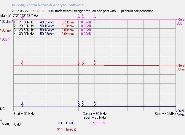
Interpolating from the measurements, I needed a capacitor of about half the value. More digging in my junk box turned up a 15 pf ceramic transmitting capacitor. Above is the VNA plot of the through impedance and insertion loss for one yagi port. There is no need to show the nearly identical plot for the other yagi port. The compensation is very effective.

At this point I had a fully functional stack switch for 10 meters. The final step was the smoke test. Since I do not have a suitable dummy load I used the 2 × 8 antenna switch to select the upper 10 meter yagi and the TH6, and connect the coax for each operating position to the stack switch. RF power is supplied by an Acom A1500. To avoid annoying anyone, testing is done when 10 meters is mostly dead, and on a frequency well away from the main activity areas.

A power of about 1000 watts was applied for a 30-seconds during each test. The results exceeded my expectations. The L-network capacitor (BIP) and the compensation capacitor (upper, lower) remained cool to the touch. The L-network coil (BIP) was warm but not at all hot. The coil in the 15 meter stack switch got hotter during its smoke test.

To complete the project I need to design, make and install phasing harnesses for the 10 meter stack. The stack switch will be installed ~140 feet (40 m) up the tower and the control lines spliced into an already present run of Cat5 cable. More on that later this summer when I'm ready to proceed.

Monday, June 20, 2022

Lightning Strikes Twice

When lightning strikes twice do you blame bad luck or do you suspect a common cause? Both can be true, but they are not equally probable. The particular circumstances tell the tale. Lightning distribution on a largely homogeneous and reasonably flat expanse of geography, like mine, is highly unlikely to favour one particular location.

My station was struck by lightning a few days ago. Again. And again it struck the Beverage system. Unfortunately it is prime growing season and the fields are filled with tall hay and the bush is overgrown. I do not venture into those areas this time of year, so it may be a few months before the antennas can be physically inspected and repairs made. What I know is that the damage is almost certainly worse and the repair will be more extensive than the last time this happened.

It may seem strange that with 150' towers and a variety of high and pointy antennas that lightning would strike antennas that are low enough to be touched from the ground. Long wires can build up a substantial charge in the presence of lightning activity, and my Beverages are between 150 and 175 meters long. Lightning is an RF phenomenon and induction of charge onto a long wire is to be expected. This happens on electric utility distribution networks for the same reason.

This is a lesson I must take to heart. It would have been prudent to disconnect and isolate the Beverages during the summer storm season when they are not in use. Many do so. I haven't since this is not an area known for high lightning risk. Experience demonstrates that my station is at high risk and I will have to take steps to deal with it.

The lightning was unexpected. Although we had several storms over the past week, that morning the sky was clear and weather warnings were for later in the day. I was working on a non-ham task in the shack while monitoring the 6 meter FT8 watering hole at 50.313 MHz, waiting for a DX opening.

A small storm cell formed to the west of us and rapidly passed overhead. The unexpected thunder and lightning didn't worry me too much, and I did briefly consider whether to shut down the station. I didn't and a minute later there was the crackle of intense arcing coming from the A1500 amplifier and bright flashes visible around the edges of the band switch. The 6 meter antenna was the only antenna not grounded. A second later the thunder boomed.

Everything kept working, with FT8 signals being decoded, but WSJT-X lost CAT communication with the FTdx5000. I shut everything off and waited 10 minutes for the storm to move well to the east. The rig, amp and PC worked perfectly when powered up. When I moved on to test the HF antennas and switching systems I discovered that the Astron RS35A 13.8 VDC power supply turned on but there was no DC output. Without it I couldn't proceed to test the rest of the station.

Now I have 2 lightning damaged power supplies. The 3A Pyramid on the right used to power the antenna switches and station accessories until it was damaged by last year's lightning strike. I temporarily moved those power cables to the Astron. Temporarily turned into a year while my attention was focussed on other projects. On both power supplies the electronics have failed, likely due to semiconductor junction damage.

I guess I can't put off troubleshooting and repairing the supplies any longer! For the interim I purchased a 4A supply at a local flea market and a friend loaned me a 25A supply to test and power the second station (SO2R). Amazingly everything works, except for the Beverages. Even the receive antenna port on the FTdx5000 was undamaged despite being connected to the Beverage system.

The Beverages could not be tested because the knob on the antenna selector wouldn't move past the first position. It was physically blocked. So I opened up the antenna switching system enclosure and discovered the problem. The picture below was taken with my phone and a flashlight.

The tabs on the rotary switch deliver 12 VDC (upper left tab) over the Cat5 control cable that makes its way to the Beverage switch about 100 meters from the shack. It's buried for most of that distance. The RG6 coax for the antenna RF follows a different route. The Beverage antennas themselves are further away. A common mode transformer in the remote switch blocks DC between the Beverages and the RG6 run the shack. Of course lightning can bridge that small gap if the path looks favourable to it.

The far right (clockwise) position is off, where the switch was set at the time. The 3 middle tabs are for the current selection of 3 Beverages. The charred and melted tabs are evidence that the lightning current found ground via the power supply by arcing to the rotary conductor. The tab adjacent to the off position partially melted and physically blocked the wiper from passing underneath. There is a separate toggle switch (not visible) to power the reversing relay that delivers DC over the RG6 feed lines to each Beverage.

I hope to have the power supplies repaired in the not too distant future. As noted, the Beverage system will have to wait until well after the hay is harvested. There should be no problem getting everything back in shape by the fall contest season, despite the unwanted extra work.

I have taken modest steps to build lightning protection into my antenna farm. I admit that I need to do more. Let my mistake be a lesson to others. I'm not ashamed to admit my mistakes -- to err is human... -- when it can serve as a learning experience.

Beyond the repairs, there are steps I will take this year to reduce the risk from lightning strikes:

  • Disconnect the Beverages and remote switch during the summer when I rarely operate 160 meters. Disconnect and ground cables when storms are in the area, at least as an interim measure.
  • Investigate lightning mitigation measures for the Beverage system that may be implemented as soon as this winter.
  • Install coax protection on all feed lines (4) coming into the house. There are 2 for the HF operating positions, one for VHF and one for the Beverages. I have a handful of VHF/UHF PolyPhaser protectors so the VHF feed line can be dealt with immediately.
  • Complete the partial and then plan a full perimeter ground system around the house, complete with additional ground rods for the coax protectors. The best way to incorporate the station ground and electrical service ground will need to be investigated.
  • Improved protection for the multitude of control cables for antenna switches and rotators. An ultimate solution is impractical so I will prioritize.
  • Improve lightning protection for the 80 meter 3-element yagi. At the moment I rely on the extensive radial system, buried cables and a spark gap for the base insulated driven element (tower).

Is that enough? We can substantially lower the risk while understanding that perfection is impossible.

I am also tempted to invest in a multi-element vertical array for low band reception to avoid the lightning risk posed by the long Beverage wires. My long term plan is for a second receive array to use during multi-op contests. It may be prudent to bring the project forward and make it the primary receive array. The Beverages would only be connected for use during contests.

As I was finishing this article a message popped up when I checked the local weather. This is lightning safety awareness week in Canada. How timely.

Wednesday, June 15, 2022

CQ DX?

It's a warm June evening and I am seriously behind in my blogging. My intent was to write nothing until one of my many projects reached fruition, and then get back to publishing more technical articles. I have three partially written technical articles that are either taking longer than I'd like or the projects themselves are incomplete. I also have less time for writing because I have unrelated interests and responsibilities.

Since bloggers abhor a blogging vacuum, I come to today's article. What is DX and when is it appropriate or inappropriate to respond to a CQ DX?

I find it more of a nuisance on FT8 than CW and SSB. That is, when I call CQ DX on FT8 or a directed CQ such as CQ AS, I get many callers from W/VE stations. I do not consider them to be DX and they are certainly not in the targetted area. What they are thinking is less certain. When I make a directed CQ I rarely reply to them unless it's long distance propagation like W6/W7/VE7 on 6 meter sporadic E. 

Calls from non-DX stations has become so common that I often uncheck the "Call 1st" box on WSJT-X. I pick and choose every call. My reaction time in reading the caller list and choosing who I reply is more rapid and easier than when I was an FT8 novice. The early decode pass added in a previous WSJT-X version helpfully provides another second or two to the time you have to act. FT4 is far less forgiving of slow human reaction.

What are the reasons non-DX stations call me? I have an idea because some of them have told me:

  • I really really really need FN24.
  • I'm a W, you're a VE. Therefore, DX!
  • Contest! The normal rules don't apply.
  • I'm QRP (or a wet noodle antenna, etc.) and I have trouble working anybody. Please?
  • Not human: robot software configured to respond to a CQ from a call not yet in the log.

Other than the last item none of these are truly unreasonable. It's a matter of perspective or opinion and reasonable people can disagree. Most who call me when my CQ is directed elsewhere stop after one or two attempts. A few don't give up. The truly annoying ones are those that call on my transmit frequency since that can QRM the targetted DX. After all, most digital operators choose a transmit frequency (audio offset) that is free of other signals and callers know that can be a good way to work you.

Sometimes I answer anyway. When I am testing propagation with a string of CQs and there is a low probability of getting what I'm calling for, working others accomplishes my main objective: being present and, hopefully, being heard if the propagation allows. I use PSK Reporter to see where I'm being heard. When the opening is alive and I'm working stations in the targetted area I do not respond to stations that are not DX. 

I am also more likely to reply to calls from hams I know personally. This is often a way to say 'hello' which is otherwise quite difficult on digital modes. There can also be a real life penalty for ignoring a call from a friend.

When I call CQ DX on CW and SSB I am more likely to respond to non-DX. They usually just want a signal report or to know they are getting out. Unlike FT8, it only takes a few moments of my time. I will not spend the required one to two minutes for an unwanted non-DX FT8 QSO while a tenuous 6 meter DX path is in play.

JTDX will filter the decoded messages to exclude unwanted areas and call sign patterns. That feature reduces screen clutter during busy DX openings. You also have the dubious excuse of not seeing the messages of callers you would rather not be bothered by. Of course you risk filtering some callers you might want to see, including those of friends or to monitor what others are working.

I use WSJT-X so I see all callers. Following the activity on the screen during hectic openings can be difficult, but at least I have the opportunity to see everything. Some days I wonder whether I am making the right choice. Many active 6 meters operators use JTDX and filter unwanted callers. It is possible that I will trial the software and its filters. Maybe I'll like it and maybe not.

At least for this season I'll continue with my ad hoc reactions when I call CQ DX.

Friday, June 3, 2022

6 Meter Sporadic E Season, So Far

As I type this the WSJT-X monitor is packed with signals. I glance at it occasionally but do not transmit. The reason is my primary motivation for being active on 6 meters: DX. There isn't much to be worked, or at least not yet.

This is not to say that I've worked no DX this season. I have. We also have F-layer propagation, better when the solar flux is high (it's low at the moment), or if it connects with northern hemisphere sporadic E. That has helped extend openings deep into South America and the Pacific.

I have yet to work a European station this year, and all I've heard is a few of the western Europe big guns. Last year I worked hundreds in May. Looking back at my records it is clear that 2021 was an exceptional year. This year appears to be more typical. The pattern up to the end of May is close to that of 2020. I am referring to the propagation here since it depends on your location. In Europe and the southern US the DX opportunities have been better. VE3 is not the best locale for sporadic E.

So what have I worked? No new countries since working CE and CX earlier this spring, but some have been heard or I've heard others working them. These include: V4, HR, OA, C5, ZL7, ZD7, OD. With 113 countries worked on 6 meter digital modes there are few opportunities to work more using sporadic E. I will keep trying! Prospects for working many more countries using the F-layer are rapidly improving. See the following chart from Macintosh:

Speaking of ZL7, here is a screen capture from a friend of mine. This occurred Thursday May 19, while I was travelling to the Hamvention. You can't be everywhere. I'll just have to be patient for another opportunity.

Paul didn't work him but a few others in the area did. Solar flux was 180 at the time, a record for the waxing solar cycle 25. We can expect a lot more DX opportunities over the next few years.

With few DX opportunities so far this season, my operating time on 6 meters has been minimal. However, I monitor activity daily. There is nothing else for the station to do since my interest in HF wanes in the warm weather and I am busy with ham and other projects. I am usually ready to pounce when I hear a station of interest. I miss a few when I am busy outside the shack.

That means you may not hear me when sporadic E is intense. If it's ordinary single hop with Canada and the US, I often stay off the air. I keep monitoring promising DX paths and perhaps occasionally transmit targetted CQs. When I do that I rarely reply to calls from nearby. For example, I typically ignore calls from Canada and US stations when I call CQ DX/EU/SA/AF/AS etc. I especially ignore those calling on my transmit frequency, since it is QRM for possible DX replies, or on the 50.323 MHz intercontinental DX window. It's a matter of courtesy.

One ongoing amusement is the number of hams replying to fake calls and false decodes. They have improbable call signs and grids, and in the latter case are almost always very weak. A couple of recent examples caught my attention. 

One was a station signing R0BOT from FN03. It was almost certainly someone accusing another certain someone of using robot software, which is unethical. Yet many stations who ought to know better called R0BOT! In a way it's touching that so many hams put an enormity of trust into the software they use.

I will only note that if this false decode was a real message we are likely witnessing the start of WW III.

Which brings us to a more interesting question: where are the blog's technical articles?

It's true that these have lagged. The warm weather has driven me outdoors and to non-ham pursuits, but I am partway through a number of projects. They'll eventually generate articles. These include:

  • Rebuild of the prop pitch motor gearbox. I've made significant progress and also hit roadblocks. More on this when I am done. On related news, I may soon acquire a spare (third) small prop pitch motor. I really need a spare on hand so that I can rapidly make a substitution when a motor requires service.
  • The UI (user interface) of the antenna selector is substantially complete, and it is communicating with the Arduino doing the actual switching chores. The project was delayed when I decided to make a fundamental change to the sharing of duties between the two software components. I have an article in the works to describe the various design choices I've made. It may be helpful to others with similar station automation aspirations.
  • I have in hand the final component for the 10 meter stack switch. Construction is not a priority right now so I may not have the stack operational until the fall. I altered the physical design from that for the 15 meter and 20 meter stack switches to ease construction and repair.
  • Repairs are needed to the 3-element 40 meter yagi. It still works well so I've procrastinated making the several climbs needed to deal with the problems.

Another bump in the road is COVID. I came back from Hamvention with the virus as did a number of my friends. It was truly a super spreader event! My symptoms were minor and no more than an inconvenience for several days. Nevertheless it cost me close to a week of productivity. I am almost fully recovered. 

This was going to be the end of the article, and then something wonderful happened.

Above is a PSK Reporter map of where I was being heard on 6 meter FT8 during the early evening of June 3. I was surprised to be flagged by E51WL on 50.313 MHz. You can see that I noticed the flag close to an hour too late. By then the common watering hole was extremely busy so I switched to 50.323 MHz to try my luck.

Within five minutes I logged 3D2AG. The amp was off for that QSO so I turned it on and kept looking to the Pacific. In the midst of a long string of CQs I was called by E51WL. We worked despite the weak signals. He was copied here as high as -2 db over the following hour. I heard many others working both E51WL and 3D2AG.

I kept CQing and monitoring but there was no more. It would have been nice to work ZL and others down under. The breadth and length of the opening and the slow QSB are strong indicators that it was F2 propagation. 6 meters will become increasingly interesting over the next few years.