
After becoming intermittent earlier this year, the antenna completely failed this summer. A group of friends came over a few weeks ago to help me take it down. Then they came back, twice, to put it back on the tower; the first lift had to be abandonned due to a rigging problem and then the wind became too strong to repeat the operation.
After all that trouble I am pleased to report that the antenna is back on the air and working perfectly. In this article I'll discuss the problems and their resolution, all of which involved the yagi's gamma match. I may say more about the challenges of tramming large yagis like this in a separate article. I've discussed tramming yagis in the past but there are always new lessons to be learned.
Gamma matches are simple devices that are difficult to accurately characterize. I have had some success modelling gamma matches with NEC2 but not with NEC5. Gamma matches are often preferred for yagis because the driven element does not need to be split at the centre, enabling a design that can be mechanically simple and robust. It is allegedly (proof is elusive!) less susceptible to conducted common mode. However it is not true that the asymmetric feed significantly unbalances the antenna pattern, especially not in a yagi. That might be fuel for a future article.
Regardless of its pros and cons, the gamma match has its mechanical and electrical challenges. These are especially important on long boom HF yagis where the feed point is inaccessible from the tower. Smaller yagis usually have the feed point within reach which simplifies maintenance and repair of matching network faults, whether it be a gamma, beta, T or other network. A network of some kind is usually unavoidable to raise the low feed point impedance of conventional yagis to 50 Ω.
Let me take you through the flaws of the gamma match that I designed and built for the 20 meter yagi -- refer to that article for details. I used variations of the design for all of the yagis I've built for the 20, 15 and 10 meter stacks, and for 40 meters. The ones for 20 meters are most notable due to their relatively large size which magnifies the flaws. These lessons may prove useful to other yagi home brewers.

On the upper left, the proximate cause of the intermittency and failure is obvious (sorry for the blurry photo). The wire (#12 copper THHN) broke off the SO239 connector. That choice of wire was a mistake. Flexing of the gamma match in the wind (it's windy 40 meters above ground) fatigued the metal. I vaguely recall using solid wire to help stiffen the large and unwieldy wire lead and gamma capacitor. That's such an obvious misjudgment that I'm surprised that I did it. I only remember that I was in a rush at the time because it was November and I was running out of decent weather.
On the lower left is the primary cause of the flexing: the PVC pipe that suspends the inner end of the gamma rod insufficiently grips the element. The shorting strap at the other end does not have this defect. Also notice the faded. supposedly UV-resistant, black cable tie due to UV and the aluminum wire wound on for insurance. Being in a hurry carries a price.
The closeup on the right was more interesting. That is scrap RG8 with the jacket and braid removed. The polyethylene (LDPE) dielectric is a good choice for making the gamma capacitor (slides into the ½" aluminum gamma rod but its UV resistance is modest. The polyethylene developed numerous hairline cracks along its exposed length, due to either or both of UV and flexing in cold temperatures. Commercial gamma matches typically use acrylic or a similar polymer that is a low loss dielectric and UV resistant.
I found a sheen of oxidation on exposed length of wire when I cut it open. That isn't serious but it was at risk of further deterioration. The other end of the wire inside the gamma capacitor had popped off the caulk cap I put on, which allowed water to seep into the other end. There was water inside the gamma rod even though the inner end was taped. Water shouldn't have built up since the outside dips down, along with the element.
It didn't help that the gamma match bounced off one of the tower's top guys when it was first raised several years ago. That may have accelerated failure and contributed to what turned out to be a out of adjustment gamma capacitor that I had to deal with.
With the antenna on the ground I got to work. There was no point berating myself for all of these preventable mistakes. Consider this exercise a learning experience for your own antenna projects. I don't hide my mistakes so that you don't have to repeat them. And neither will I! Writing a blog does not make me perfect or blameless.

The new gamma match has several improvements:
- I fabricated a clamp out of sheet aluminum allow for the top of the PVC insulator and a hanger from the coax connector secures the open end of the wire to the gamma capacitor. Flex has been almost entirely eliminated.
- The solid vertical wire was replaced with #12 stranded wire. A new length of scrap RG8 was used for the wire which forms the inside of the capacitor.
- All wires are taped with Scotch 33+ for UV protection, and connections are sealed.
- Cable ties on the boom, coax choke and on the gamma match are covered with Scotch 33+ to protect against UV, even for supposedly UV-resistant cable ties. I saw a friend do it and it seemed like cheap insurance. It also doesn't hurt to coat rigid PVC even though its UV resistance is good.
- The open end of the gamma rod (not in the picture) has been sealed against most moisture.
In other words, I saw no need for a redesign, just incremental improvements. The coax choke tests good after 5 years; the winding diameter is within the bending radius spec for LMR400, but it doesn't hurt to check that it's still okay. One reason I use coax chokes rather than ferrite chokes on these antennas is to avoid excess heating and failure due to common mode (antenna) currents when the tower is shunt fed on 160 meters.
While I had the antenna on the ground, I did a complete inspection. Problems can become apparent after being on the high tower for 5 years (since 2019).

I didn't mention where I got my hardware when I built the antenna since it might have been taken as an endorsement. I can say more now that the antenna has been service for several years. The 5/16" galvanized saddle clamps on the left were bought from K2SSS on his eBay store. There is no corrosion on the bolts, saddles or nuts, and none of the nuts have slipped. I am happy with them.
The ⅜" clamps on the right were purchased from DX Engineering. Cycle 24 galvanized clamps are on the mast and the two stainless clamps with solid aluminum saddles are on the boom. I abuse these clamps quite a lot when raising and lowering the yagi and they show no signs of wear. I lubricate the stainless threads before tightening them to reduce the risk of galling, especially when tightening and loosening the nuts while they're under heavy load.
As an example of heavy loading, notice the tape marks on the boom. The near one is at the CoG and the one centred on the mast is at the centre of the boom. They are 16" (40 cm) apart. The boom-to-mast clamp is moved to the former for tramming. Thus the antenna is heavier on one side when properly mounted. I have to move the boom after it's raised and before it's lowered. That puts extra stress on those stainless saddle clamps. I could have used a boom counterweight to place the CoG at boom centre but the antenna is already very heavy.
The galvanized ⅜" u-bolts holding the elements were acquired from a commercial tower service company and those fasteners are not sold retail by the Canadian manufacturer. They remain in excellent condition. Other unbranded plated and galvanized u-bolts fared less well. I cleaned and then sprayed them with cold galvanizing compound. I've had good luck with the Rustoleum brand in the past so I'll see how it performs in this case.

I skipped over adjustment of the gamma match to keep the mechanical information contiguous. So let's backup to cover that. I used rigging similar to when I originally adjusted this yagi. It's difficult to lift a 120 lb antenna in a manner that is safe, high enough to achieve a "free space" impedance, and that is not significantly affected by the near field environment. There are guys, towers, coax (for tuning) and even an aluminum ladder in the vicinity. I did not want to incur the time and trouble for elaborate rigging to put it in a more favourable area of the field.

A ½" rope runs between the guyed towers at about the 70' level, near guy stations -- the towers are 200' (60 m) apart -- and please don't try this with self-supporting towers. This rope is attached to another rope that runs through a pulley to a winch on the ground that is anchored to a tree. Ropes on both sides of the boom allow the yagi to be oriented in any direction, including upward. A chain and shackle at the centre of gravity (CoG) allow freedom of movement -- the rope freely passes through the shackle.
Because it takes a lot of cranking to lift the yagi due to the winch's 5:1 winding ratio, this time I anchored the second rope to the tower and used a pulley on the winch cable to speed up the lifting and lowering of the yagi. The pulley functions as a reverse block and tackle to effectively lower the winch ratio to about 3.5:1.
The driven element side is tilted down to the ground for adjusting the gamma match by pulling on a rope. There is a long length of LMR400 coax to the analyzer, which is entered into TLW or similar tools to convert the measured impedance to that at the feed point.
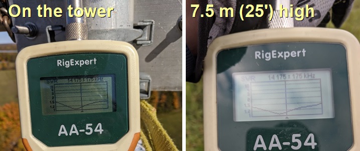
I did the coarse tuning with the yagi level at about 2.5 meters height, where the gamma match was easily accessible from a step ladder. I then lifted it higher and tilted it down for adjustment. At 7.5 meters height, a ladder is needed to reach the gamma match (6.5' or 2 m from end of the boom) when it is tilted down.
As expected, the element tap point was approximately correct. By fine tuning it, I achieved a 50 Ω match at about 14.150 MHz which, for this antenna, keeps the SWR below 1.5 across the band. The bulk of the improvement was in the value of gamma capacitor.
The impedance became unreliable when the antenna elements were approximately parallel to the guys, despite being segmented into non-resonant lengths, and drifted when the reflector was tilted downward. The reliable readings were with the antenna level and the elements at right angles to the tower guys at either side.
After all the fussing the result was perfect. The antenna SWR curve matches the EZNEC (NEC2) design, and it barely budged after it was lifted onto the tower. Several hours were required to dismantle the rigging for lifting and lowering the yagi, and then to remake the coax connections and thoroughly weatherproof them. There was no moisture incursion or corrosion on any of the connections so the original weatherproofing performed well.

Of course I was eager to power up the stacks after I descended for the final time. They are working great. One of my tasks on the way down was to pull off the compensating L-network and delay line for the previously misadjusted gamma match. They are happily no longer needed. The extra RG213 patch cable will come in handy.

I'll close with a view at the antenna looking due north. There's a beautiful view of a lake and the fall colours from 40 meters up. But I have had little luck persuading others to climb up and enjoy the view. Maybe they suspect that it's a trick to get them to help with the tower work, and they may be right! It was a perfect warm and sunny fall day for completing the tower work. Colder weather is approaching.
CQ WW SSB is this weekend. I'll do it as a single op in a category that I have yet to pick. The station isn't ready for another multi-op. Perhaps for the CW weekend.
No comments:
Post a Comment
All comments are moderated, and should appear within one day of submission.