When you purchase a product you accept the decisions of its designer. If those choices are unacceptable you can turn to a competitor's product. Griping about what you don't like accomplishes little. Sell it and move on. We all make mistakes.
When you choose to design and build your own equipment and you don't like it, you can only blame yourself. Discard it and purchase a commercial product. Or you can try again. For my custom software-based antenna selector, I am trying again.
Design iterations are at a far slower pace than I'd like. That's the penalty of doing it myself. Were I to apply myself full time to the effort it would have been accomplished long ago. But this is not a job and my time is filled by other projects and non-radio activities. So it happens when it happens.
I will point you at the article in which I initially described the system for details that I won't repeat here. I have also written about many of its shortcomings that became especially apparent during a multi-op contest. If a guest operator can't figure it out with a modest amount of acclimatization, there is something amiss. A good and intuitive UI (user interface) and UX (user experience) is difficult to achieve. Many ham radio software products don't even try.
A major source of the existing system UI issues were due to my original hardware-based design. Its complexity reflected the complexity of my station, and the necessity of switches and LEDs to communicate system state and buttons and switches for antenna selections. I cast it aside and did what I should have done at the outset, which was a software-based system. My mistake was to keep too many of the original features that were driven by my self-imposed hardware mindset.
The UI on the PC screen is just one component of the antenna selector system. It is in communication with an Arduino that houses the actual antenna switching software. A final component is the assembly of relays and electronic switches which control the multitude of switches scattered in the field and on the towers. But all of that is hidden from the operator; the UI is the visible face of the system.
My intent is to replace the UI while leaving the rest of the system as is. I have been deferring new features in anticipation of the UI redesign. New features can be added later.
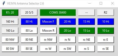
While many of the deficiencies were mentioned in the previously linked articles, here is a quick rundown. The screenshot shows a slightly modified UI to accommodate the reversing function of the new 40 meter reversible Moxon.
- There is no list of available antennas on the selected band. The antenna selector buttons (top row, second from both the left and right) select the next available antenna for the band in a predetermined order. An antenna that in use by the other radio is skipped. Essential data is hidden repeated clicking is slow and prone to errors.
- Several antennas can alternatively be selected with the High/Low buttons for the low bands (160, 80, 40). That's confusing to guest operators, and occasionally myself. My intent was to achieve functionality similar to that of the stack selectors for the high bands. It was an idea that sounded good in theory but not in practice!
- It is easy to click the wrong mode and direction buttons. For example, selecting "20 Hi" instead of "15 Hi" because you fail to notice which radio and band you're on. The mistake is particularly easy to make when dealing with the intensity of SO2R and 2BSIQ.
- The direction buttons are not sensibly arranged. This was a temporary solution until I had time to expand the UI to include a bearing map centred on my location. Temporary solutions tend towards permanence.
- There are two Beverage receive systems. The UI only controls the large 6-direction system and not the new 2-direction system (eventually 3). The switch box for them supports swapping the systems between radios, while the software does not. Hardware and software must change.
- Lack of manual override and reset features when communication with the logging software or Arduino is lost due to RFI or bugs. It doesn't often happen but when it does it disrupts contest operation for a few minutes.
- Knowing where an antenna is pointed. Guest operators have difficulty remembering all of the antennas, and associating a physical rotator controller with an antenna (or antennas).
- Separate UIs on different computers for multi-op contests are needed. Although the new UI won't support that immediately the UI should accommodate SO1R, SO2R and multi-op with a unitary design. Having one UI on a PC between the operators, and sharing the mouse, is far from ideal.
That's a frighteningly long list! I can only do the work in stages, so I will aim to do the high impact items first. Before I can do that I need to develop a new UI framework that addresses the major defects. After that it's features that go "under the hood" and are therefore less impactful to the UX.
To familiarize myself with alternative layouts I took to Python to construct a "dummy" UI that I could play with. Alterations are easy since the experimental UI is a facade with no code behind it. As for the existing UI I turned to Tk since that's what I'm most familiar with. Others prefer a web interface or other UI packages. There are many to choose from and I won't recommend one over another.
The following is my first draft for the new UI. Embellishment has been omitted, such as the use of colour cues which are used in the current design. A simple construct is sufficient to prototype the design process without getting bogged down in details. It is more useful than a paper exercise since it is tangible.

Although it appears bulkier, the area of the window is almost identical to the original. This is critical to conserving screen real estate. I like to fit all critical windows needed for contests onto one PC display.
These are the principal attributes of the new UI, and how they are intended to address the listed shortcomings of the current UI.
- All of the possible antennas for a band are shown. The fixed layout limits this to 6. That seems plenty except that the number includes stack configurations and direction switching. For example, all 6 are used on 80 meters.
- Unavailable antennas will have their buttons disabled and given a distinct colour (not shown) so that the operator knows at a glance which antenna is in use and what is and isn't available.
- Showing the antennas for the other radio can aid communication between operators (even if it's one SO2R op) to request an antenna that is in use. I do not use triplexers or similar equipment to allow simultaneous sharing.
- Multi-op use will display the other side of the UI for situational awareness. Left and right radios will be distinct by their position and colours, and that is the case whether multi-op or SO2R. Note that I removed the R1 and R2 labels since they are largely superfluous.
- Fixed antenna directions are also shown in the adjacent direction box. Omni-directional antennas are shown with an "O" which (to me) conveys the meaning. I tried leaving it blank but that proved to be confusing and required spending more time interpretting the displayed information. The direction boxes may in time allow direction selection for rotatable antennas.
- The receive antenna directions are shown on a great circle map centred on my QTH. Depending on the system employed, buttons will be enabled or disabled. It is fortunate in my case that the direction buttons don't cover any significant land mass. The direction labels may be redundant since their positions on the map seem sufficient.
- The bottom row of buttons are to enable/disable receive antennas and to select the Beverage system. I may add the capability to cause receive antenna selection to command the rig to enable/disable the receive antenna port. I do it now with a soft button on N1MM's bandmap window but that requires an extra mouse click. The button layout requires more thought.
- The top row shows no buttons to control the Arduino. I would like at least a reset button for rapid recovery from most bugs and RFI glitches. Additional buttons may be added to toggle BPF insertion and automatic/manual operation, and to restrict operation to contest bands versus all bands. Note that I use the antenna selector for all HF operating, not just for contests.
- Extendible to new antennas and features as the station continues to evolve. There won't be too many new antennas but change is integral to my amateur radio journey.
It is not the purpose of the UI to please everyone. Others would surely make different choices. Some I might like if they don't over-complicate implementation. There are also many hams, especially older ones, that will always prefer the tactile feel of knobs and switches. I've moved past that. The only physical feedback is the click clack of relays under the operating desk. Even that will disappear should I move the switching components out of the shack -- there is no reason to keep them near other than ease of maintenance or for disconnection when lightning approaches.
Ideally the UI will in a sense disappear. It can be counter-intuitive that a well designed product doesn't draw attention to itself because it works so well. I doubt that I'll achieve this lofty ideal. I will be satisfied when it enables operators -- myself and guests unfamiliar with the station -- to do what they need to do with minimal friction.
There is more design work ahead of me. I would like to begin implementation this summer and finish it by year end. The work won't take 6 months of effort, it's just that this is one of many things that I need to get done.


