Tuesday, October 10, 2023

Inspecting a Bencher Skyhawk

This is not a typical product review. Indeed, it is really not a review at all. But as I inspected, cleaned, reassembled and installed the Bencher Skyhawk tri-band yagi I recently purchased secondhand I thought that it might be instructive to look at how an antenna ages and how it is designed. Nothing lasts forever, and problems crop up in the best antennas. They are totally exposed high up on a tower and endure everything nature can throw at them. 

Mine is an approximately 12-year old Bencher Skyhawk, a product which has since been transferred to DX Engineering. The new owners have made only a few small changes so that the antenna you can buy today is substantially the same as the original. My observations are mostly applicable to both. 

The electrical and mechanical design of this no-trap tri-bander is very good and reviews are almost all very positive. This is a fine antenna. That's why I bought it. But a 12-year old antenna is not a new antenna and time has taken its toll. That's one good reason you don't pay new prices for old merchandise. The resale prices of many products fall precipitously because they age poorly.

The Skyhawk is now on the air at VE3VN. Raising of the antenna was described in a previous article.

This article contains my notes and observations. As already said, this is not a review but a collection of my impressions from inspecting, assembling and raising the antenna. It was an interesting study.

Electrical design

A multi-band yagi is very difficult to design and optimize. This is true with or without traps. All the elements interact, so that even non-resonant elements, and even the tips beyond the traps, have induced current and their fields add to those of the resonant elements. There are no analytical solutions except in the most trivial of cases. 

An iterative numerical process is needed to solve the design problem. Before computer modelling, trap yagis had to be refined with great time and expense on a test range. Many manufacturers didn't even bother trying. I've done manual iterations using EZNEC to optimize small yagis but large ones like the Skyhawk require automated algorithms. For my own antennas, I most often take an already optimized design, whether one band or more, which I may tweak to meet my personal performance objectives.

Measurement notes: The SWR plots were made with a RigExpert AA54 in the shack, through about 40 meters of low-loss coax (except 2.5 m of RG213) and a 2×8 antenna switch. I checked the SWR at the feed point after it was raised but the measured impedance is affected by body proximity. The effect increases with frequency: little change on 20 but noticable on 10 meters.

The Skyhawk is optimized and it is a good design. Although I have not developed a computer model of the antenna, nor have I read an engineering review of it, it appears from its behaviour that some gain may have been sacrificed in favour of an excellent match across all three bands.

There's nothing wrong with that and it may be better for the majority. I tend to favour a little more gain. But that's a nitpick.

12 years of wear

Nothing lasts forever, and that includes antennas. Exposure to the elements takes its toll no matter how good the antenna's mechanical design. An inspection found problems, both small and large. These were corrected before it was reassembled and raised.

  • Rivets
  • Driven element spacer
  • Grease

I laid out the pieces of the antenna on the deck to do the inspection and element assembly. Rivets had to be removed from several elements to break into sections that would fit on the truck. 

It was an excellent opportunity to inspect how rivets perform over time. I was interested because I've never owned a yagi that used rivets and I didn't use them on my many home brew antennas.

Rivets

Rivets have always struck me as inadequate for joining the sections of tapered element since they are quite small. I wondered if they were strong enough to last and whether the longitudinal stress on the element would accelerate failure of the softer aluminum alloy tubes. Disassembly of the antenna for transport gave me an opportunity to inspect their long term behaviour.

On the left is an improperly seated rivet head. I drilled out several of these to inspect the holes and insert new rivets. There was no obvious damage to the tubes or rivets in most cases so the protruding heads were likely due to mishandling of the rivet tool. The heads of all the rivets protrude around most of their circumference since it's flat and the tube is cylindrical. That isn't ideal but it seems to work.

On the upper right is a damaged hole where rivets were drilled out to disassemble the element. The sides of the hole are clean so it is possible that it was due to careless application of the drill. I left it as is and inserted a new rivet. The resulting bond was good since the rivet head is larger than the hole in the outer tube and the inner tube wasn't damaged.

Close inspection of the inner tube of one telescoping joint was enlightening. The hole is longitudinally elongated and the inside hole rim is roughly bevelled. The elongation is slight, probably no more than 0.020", and it is sometimes less (my calipers didn't fit very well for accuracy). This is what I expected since mechanical stress on the element is primarily longitudinal. 

The ⅛" diameter of the stainless rivets is a small, hard surface that can amplify the stress and push the softer aluminum aside. However, it isn't enough to be of concern so I inserted new rivets and continued.

The outer diameter (OD) of the smaller telescoping tube is less than the larger tube's inner diameter (ID). In both cases the wall thickness is 0.058", which is the most common US made aerospace alloy tubes used for telescoping yagi elements in ⅛" steps. For a press fit the wall would have to be 0.0625". That leaves a maximum gap of 0.009" when the tubes touch on one side. The tubes thus slide together very easily. Please note that the gap is less than it appears in the pic due to shadowing.

The antenna obviously works well despite the gap, although it bothers me a little. A press fit a poor choice for antennas since if you could insert the smaller tube it'll probably never come out again! Oxidation, stress and galling take their toll. For full circumference contact the outer tube must be slit and a gear clamp used to squeeze them together. That introduces two points of failure: the slit and the clamp. High quality stainless clamps are essential for reliability.

There are other ways of bonding telescoping tubes. A few of those which are applicable to element tubes were described in the blog when I was building my many yagis. Each method has its pros and cons, including rivets. Perhaps rivets aren't so bad after all.

There are many online resources that explain rivets and how they work, and how to use them. High tensile strength stainless rivets are inexpensive and widely available. It's well worth wasting a few to practice using the rivet tool. I drilled a few ⅛" holes in scrap aluminum and practiced until I was sure of what I was doing. The rivet tool came with the antenna.

It takes a lot of force to seat the rivet and break the narrow neck. I found it easiest to place the element and tool on a solid surface and press the upper handle with one hand while using my other hand to align the tool head with the tubes and to ensure contact between the rivet head and the tool tip. Inset is a closeup of properly seated rivets that were drilled out. You can see how the rivet bulb expands the shank upward to squeeze the tubes together against the rivet head.

All conductive joints in a yagi should be coated to prevent oxidation, prevent binding of telescoped tubes and assure conduction. Many hams skip this step and they should not. I've taken apart many "dry" antennas that required restoration. Some use dielectric grease, and it can work well if it doesn't dry out. A better choice is a conductive grease, which is essentially dielectric grease with a suspension of microscopic metal particles.

The manual states that the Bencher product was shipped with a product called Butter-It's-Not. The name is familiar but I've never seen it and I had difficulty searching for it online -- searches favour links to margarine sites! In any case there are many products. Whatever was used on my Skyhawk, all the grease had dried, leaving a residue of the suspended metal and whatever else. From the residue at least two different products were used.

I lightly sanded the exposed joints to renew them and greased them. Rivetted joints were left as is. The product I use is Noalox. I've had good success with it. The joints remain slippery after many years. I know there are better products that I have less experience with so don't take this as a firm recommendation. My squeeze bottle is so old that the plastic is cracked and repaired with clear packing tape. I've greases joints in countless antennas over the years. A small amount goes a long way. It's cheap insurance so don't skimp.

Driven element spacer
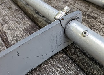
Feeding multiple elements directly from a common feed point puts them in close proximity. Without one or more spacers along their lengths the driven elements would strike one another when the wind is more than a light breeze. That would be catastrophic since the transmitter would fault due to SWR when they make contact.

The Skyhawk uses one spacer on each side of the boom to hold the three driven elements. Only the 15 and 20 meter elements are at risk of touching, and that's very unlikely unless the tubes are severely stressed. If wind or ice of such severity were to occur, you'd likely have bigger worries!

A common complaint in many online review of the antenna is that over time the bundle of driven elements develops an S curve. The reason is that the spacer gradually slides sideways on the 10 and 15 meter driven elements while waving in the wind. When it slides it tends to stay in its new position because the tube fit is tight. Only on the 20 meter element is the spacer trapped so that it can't move.

The plastic spacer is very tough but not indestructible. Apart from the unsightliness of twisted elements, the spacer and tubes are placed under increased stress. You can see where one of the spacers cracked, not surprisingly on the 20 meter element where the hole in the spacer is largest. I'm surprised that this product flaw has not been resolved.

My solution was to fix the spacer position on the 10 and 15 meter elements. A combination of small hose clamps and UV-resistant cable ties are lightweight and get the job done. It takes very little resistance to prevent the spacer from creeping.

I ventured to repair the cracked spacer rather than order a replacement. I drilled a hole and threaded a heavy duty cable tie through it. The tie braces against the element to bind the sides of the crack. 

When kept in the correct position, the radial stress ought to be low. The plastic itself is quite tough (it survived the crack). Time will tell whether my repair is effective.

Element-to-Boom clamps

The element-to-boom clamps have no way to fix the element centre to coincide with the boom. All the elements are insulated from the boom with bonded plastic sleeves and you simply judge by eye (or a ruler) as you tighten the clamp bolts. Perfect centering is irrelevant to performance but I do it anyway.

The driven element clamp alignment is more critical (picture is from the DXE manual). These three elements are split for feeding. Rather than one long plastic sleeve, there's a short one on each side of centre. The straps for feeding the elements in parallel are wide and carelessness can cause a short between the strap and the element clamp (which contacts the boom). I made sure the clamps were properly tightened to prevent the elements from creeping due to wind stress. 

I wish the design of the feed and clamps were better. However, I haven't heard any complaints on various fora of shorts developing over time. It must happen but perhaps it's rare. A raised lip or rim on the inner side of the sleeve would reduce the risk.

Another peculiarity (or benefit) of the clamp design is that there is no way to position or align the elements along the boom. There is a bolt that run through the upper half of the clamp and the boom. In a few cases the bolt does double duty to bond the boom sections and the boom compensator.

Alignment was excellent except for the driven elements. They are less than 2° askew. It isn't noticable except when you sight along the boom. The PVC element compensator doesn't age well so it is no longer straight. That isn't the fault of the clamp, and it doesn't matter.

Boom attachments

The antenna has no boom truss despite its 24' length and with the longest (heaviest) 20 meter elements mounted at each end. Despite that lack the boom is pretty hefty and sags very little. You can get an idea from the view along the boom towards the reflector end.

You really don't notice it from the ground. Aside from aesthetics there is a question of how much severe weather load the boom and mast clamp can tolerate without the truss. The antenna is engineered for high winds and some ice so I am not especially concerned. But I do wonder how it'll fare in our harsh winters and occasional severe ice storms. On the other hand, elimination of the truss keeps the mast free of obstructions.

When I removed the antenna from its previous owner's tower I was unfamiliar with the design of the mast clamp. I automatically loosened the saddle clamps and sent the antenna into the hands of the ground crew below. The u-bolts don't pierce the saddles so it isn't difficult to drop the loose saddles.

I later came to understand the two-part design. The mast side of the assembly can be left on the mast for both raising and lowering. The upper nuts on the boom side of the clamp fit into the keyholes of the mast plate and drop into the slots below. When that's done the antenna is secure. The lower nuts can be threaded on and all 4 bolts tightened. The reverse procedure is performed for removal of the yagi.

Keyhole mounts are found on all types of hardware, but this is the first time I've seen it on a yagi. I like it. 

When we raised the antenna onto my tower, the mast clamp was already installed and all I had to do was direct the nuts into the slots and have the crew lower the antenna an inch. There was no fussing with multiple saddle clamps (often with short u-bolt legs that require near perfect alignment) to secure the load. 

Balun and coax

The balun supplied by Bencher is more compact than the one included by DX Engineering. It appears to have weathered well. I can't say how well the PVC electrical box for DX Engineering's common mode choke will survive other than to note my poor experience with the same enclosure used by Balun Designs.

The balun fits snugly under the boom using special brackets to keep it centred and with adequate space for fitting and weather proofing the coax. I tested it with a dummy load on the workbench and it tested fine, with inductive reactance gradually increasing with frequency due to the pigtails. I do not have a fixture for testing common mode rejection. The quantity and type of ferrite beads determine its performance.

The location of the feed point is not convenient for attaching the coax and rotation loop. The Skyhawk includes a boom bracket to support the coax and thus reduce stress on the connector and balun. Unfortunately, that puts the coax even further out. It isn't very far but you must be comfortable leaning out from the tower to do the work.

Since the feed system is below the boom the coax is routed above the boom. The rotation loop is located on the opposite side of the mast and paired with coax dropping down from the 6 meter yagi at the top of the mast. It is possible to put the rotation loop on the same side of the mast by routing it down on the outside of the driven elements, except that the coax has to be kept rigid as it passes the balun to avoid jostling during rotation. A few more feet of coax makes a cleaner rotation loop on the far side of the mast, so that's what I did.

Tube caps

The antenna comes equipped with plastic caps for the boom and element tips. Only a few of the elements had caps on my Skyhawk. I prefer no element caps so that water can freely flow out should any get in. 

I have the boom caps and I put them on. Insects are a greater risk in booms since they are large. It's a trade off. Depending on local conditions it maybe sensible to cap all of the tube ends, or none of them.

So far...

I'm happy with the Skyhawk. The first contact was with VK9LAA and I have made many other DX contacts since, including several of the current DXpeditions. It's easier and quicker to turn this antenna than the prop pitch driven big yagis. Although it is not my best antenna on the high bands, it is usually sufficient to make the contact. The agility it brings to my contesting is very welcom. 

For most hams it would be a fine antenna on its own. Just make sure the tower and rotator are up to the job. There are many elements and that adds up to a high wind and ice load. 

Another consideration is the price. There are few antennas I would buy new and this one is no exception. Material prices have skyrocketed over the past few years and that makes up a substantial portion of the manufacturing cost. The Skyhawk is not out of line with the prices of similar antennas. I don't see many available on the used market. I buy my antennas used or I build my own, with infrequent exceptions.

Direct comparison with the TH6 hasn't yet been done since their gains will be close and the confounding factors many. 1 to 2 db of difference is difficult to reliably discern by ear or S-meter on receive. On transmit it's a different matter: the extra gain of a no-trap design will be noticed. This is often also true when comparing my stacks to smaller yagis. The contest pile ups are deeper and they last longer.

Most hams are fortunate to have one yagi for the HF bands, and two is uncommon. Easy comparisons are impossible. Hence the reliance by some hams on myth and lore, unreliable opinions and advertising. We do have a tendency to convince ourselves that whatever choice we make is the best choice because it is our choice. Physics begs to disagree.

Thursday, October 5, 2023

Rearranging Yagis

No long ago, I described that during this fall's antenna work several yagis would be moving or removed. You can see a graphic of the plan in that August article. Here it is in words:

  • Remove the TH6 from the rotatable side mount halfway up the 150' tower
  • Move the XM240 from the Trylon to the position vacated by the TH6
  • Raise the recently acquired Bencher Skyhawk onto the Trylon

Later in the article I'll discuss why I'm doing this. But first I'll describe what was done.

Not including preparation and cleanup, the latter two items were accomplished in one day with the help of Alan VE3KAE and Dave VE3KG. I had hoped for one more helper but we made for it with mechanical muscle.

Since making my annual plan, I had a change of heart and the TH6 was moved rather than removed. I spent a couple of hours in the workshop to make a fixed bracket for the big tower. I installed it a little above the rotatable side mount. With Alan's help a week earlier we lifted the TH6 the short distance to its new perch. It is fixed to the south (170°). It's been here before. That freed the rotatable side mount for the XM240.

I have written so much in this blog about the various methods for raising yagis that I won't repeat myself. Do a search of the blog and you can read all about tram lines, tag lines, pulleys, vehicle power and much more. One picture will suffice for this article, of Alan posing with the XM240 at the tram line's launch point.

The only significant difficulty was on the smaller tower, the 70' Trylon. Being close to the house rather than in the middle of a hay field like most of my towers, there are obstacles. The yard area of my large property is very pretty with many trees, but they pose a challenge for raising and lowering antennas. For one thing, they grow! The challenge increases every time I lift or lower a yagi.

The XM240 and Skyhawk are quite large. Each weighs about 75 lb; the original XM240 is lighter but this one has been strengthened per W6NL. The antennas must land or be lifted a distance from the tower so that the elements and boom clear the overhead cables and several large and growing larger trees. Steering with tag lines is critically important. Finesse is needed more than brute strength, however the latter is needed when the yagi is close to the ground and far from the tower base.

I will emphasize one very important lesson about tag lines. Steering a yagi requires two tag lines, one on either side of boom centre. They are either attached outside an element clamp or prevented from sliding with a clamp or other means, and be easy to remove once the yagi is attached to the mast. 

Two tag lines sounds like a job for two hams. Wrong! No matter how many times I have tried it over the years with two people, it is almost always impossible for them to perfectly coordinate their actions and intentions. If you don't believe me, try it. But try it with your yagi and not mine! Element tips are fragile.

Instead we divided the work. One person drove the vehicle for lifting and lowering power, one controlled both tag lines and the third person relayed communications between the driver and the handler of the tag lines. 

The latter job went to me since I have the most experience with the delicate matter of steering yagis. I was also highly motivated since it would be my own yagis at risk! Communications was key since the vehicle was in the driveway and out of sight of us, and the driver could not see the tower or the yagi (trees and house blocked the view). 

It was entertaining and tense at times but we got it done without damaging the antennas. For added excitement, we had to avoid bumping the wireless internet radio mounted near the top of the tower. Knocking it out of position would involve a costly service call. 

I climbed the tower once to uncouple the XM240 from the mast and again to attach the Skyhawk to the mast, all while the vehicle was holding the yagi's weight. I won't get into the rigging details since, even with pictures, it is likely to be more confusing than enlightening. The rigging allowed the vehicle (my lawn tractor to lower the XM240 and a car to raise the Skyhawk) to move in a wide compass of directions while the line going up the tower stayed in a fixed position where it was clear of trees, tower and internet radio.

The pictures show the successful results. The antennas checked out and I reconfigured my software to reflect the changes. To my chagrin, that uncovered a couple of bugs that I tracked down and successfully fixed that same evening. 

Over the next several days I finished the job of boom trusses, dressing cables and weatherproofing. Late September and the first days of October were unusually warm and sunny. Temperatures soared to 30° C. That's record breaking for our northern climate at this time of year. 

As I write this, the one outstanding task is hooking up the TH6. The Heliax is connected by I still have to reconfigure the antenna switches to free a port for it. Other than that, the XM240 and Skyhawk are fully operational and being used on the air. It's auspicious that my first QSO with the Skyhawk was VK9LAA.

In a forthcoming article I will talk about the Skyhawk in depth since I found the antenna design to be quite intriguing. It is well worth a close look. The XM240 I've owned for quite some time, from before I moved to this QTH. I bought it when it became available during the planning stage while I continued to live in the city. After the move to this QTH, it has been on a variety of towers:

  • Onto the Trylon when it first went up the first winter
  • Moved from the Trylon to the top of the 150' tower when it was built the next year
  • Removed from the big tower and put back on the Trylon
  • Now it has moved from the Trylon back to the big tower, but side mounted

This is all fine, but by this point many readers must be thinking: why? Why keep moving these large yagis from one tower to another? Surely it's better to decide what I want or need, put them up and keep them there. 

There is a method to my madness. I am not intimidated by big antennas and towers, and I have the experience (and time) to undertake these frequent changes. I choose where I want an antenna based on the state of station construction and my operating objectives. The latter is primarily contests. For daily operating there is no great need for so many towers and antennas. Of course many non-contesters do it anyway, just because they can and it can be a lot of fun. 

I'll take you through my thinking so you can better understand why I've taken the trouble to do all this work. While you read, keep in mind that my primary operating activity is contests. Several of these points were documented in the 2023 station plan that I published in January.

Traps: Traps in yagi elements have loss and narrow the SWR bandwidth. I have long yearned to free myself of them but the reality was that I had them and they filled a need. I've reached the point where I can mostly eliminate them. The Explorer 14 was sold last year and the TH7 sold this year. As I explain below, I decided to keep the TH6 to fill an ongoing need.

Solar maximum requires more high bands agility: 10 and 15 meters conditions are great and they're going to get even better. With only so many hams and hours in a day, it is no surprise to find increased activity on 10 and 15 meters, and less on 20 and below. For the next few years it is valuable to have more antenna options on 10, 15 and 20 meters. For the coming contests there are now 3 antenna choices on those bands, and the ability to split the stacks.

Rapid access to W4, Caribbean, South America and Central American: Several years ago, before building the rotatable side mount, I fixed the TH6 south. It's back but a few feet higher. Skip is shorter when the solar flux climbs and there are more southern US stations available to be worked on the high bands. It isn't a high traffic path so it typically isn't desirable to point the better antennas in that direction. With a click of the mouse, the TH6 provides instant access to the south for DX multipliers and the southeast US. Once the targetted station is worked, another click returns the operator to where they were.

Prop pitch motors are slow: The upper yagis of the 20, 15 and 10 meter stacks and the 3-element 40 meter yagi are turned by prop pitch rotators. They are poor choices for rapidly working multipliers. It is more profitable to use them for running and long DX openings. I turn them to a direction and leave them there for a long time. The smaller and lower yagis are used for less productive paths, shorter paths (e.g. US) and multiplier hunting.

Unfortunately, the changes I've made are not all positive. Trade offs were unavoidable. These are the most notable cons of the new arrangement:

  • Reduced capability on 40: Pre-sunset and post-sunrise the DX elevation angles tend to be higher than during the night due to D-layer absorption. The XM240 at half the height of the 3-element yagi often outperforms its big brother at those times. Since the side mount only allows 130° coverage from southeast through west, I may suffer a deficit to, for example, Europe in the late afternoon. It can still be used effectively in the morning towards the Pacific and South America. I plan to replace the XM240 next year with an antenna that has more complete compass coverage and that has no loading coils. I can live with the XM240 for one more year.
  • Potential interference on 20: With so many yagis there is the ever present risk of destructive interactions. The 3-element 40 meter yagi was expressly designed to avoid pattern degradation of the 15 meter stack. I have not modelled the interaction between the tri-banders and the stacks, however I know the TH6 and Skyhawk won't interact because the TH6 points south and the Skyhawk is to the west of it. Due to the respective heights of all the yagis, I suspect the only significant issue may be on 20 meters with the lower yagi of the stack. Modelling the scenarios will have to wait for inclement winter weather when I'll have more free time.

I believe the negatives are far outweighed by the positives. At least for my style of operating. The 40 meter issue is short term since I plan to replace the XM240 with a better antenna, hopefully in 2024. Coil loaded elements, like traps, increase loss and decrease SWR bandwidth. Yagis suffer more than single element antenna because they are inherently high Q antennas and the radiation resistance is low.

The agility I've gained on the high bands is worth the risk of yagi interactions. Pattern degradation depends on where the yagis are pointed so it will occur only some of the time. In any case, I don't require ultimate performance from the tri-band yagis since they will be mostly used for rapid multiplier hunting.

With this big job out of the way I can focus on several other antenna projects. I'll write about each of them as those projects come to fruition.

Tuesday, September 26, 2023

Beverage Lightning Protection

Beverage receive antennas are very susceptible to lightning. They are long wires that at close to the ground and grounded at both ends. While direct strikes are not rare, the greater threat is typically secondary strikes (low current lightning branch) and inducted current from a nearby strike. I can personally attest to the lightning risk, when my Beverage system has been struck not once but twice.

This summer I removed the head end electronics of my three reversible Beverage antennas, disconnected the feed lines and directly grounded the antenna wires. I rarely operate 160 meters during the warm months since noise is high, activity in the northern hemisphere is low and the radials of the primary 160 meter vertical are removed during the haying season.

One of my summer projects was to add lightning protection to the Beverage antennas. It isn't difficult and there is ample information available on how to do it. Nevertheless I moved slowly. I wanted to better understand how the protection systems work before ordering parts and making the modifications. I am now better informed though far from being an expert. 

When I was satisfied with what I learned I ordered the parts and made the modifications to the Beverage head ends. After completion I tested them to confirm they still worked as they should and then reinstalled them in the field. The Beverage system is back in operation and ready for the fall and winter season.

The design I settled on is a melding of the methods I gleaned from W0BTU and VE6WZ. Those weren't my sole sources but they were well documented with good explanations. I also read what W8JI and ON4UN (Low Band DXing) had to say on the topic and I delved deeper into the circuits and explanations from commercial lightning protection device vendors. Any mistakes or misunderstandings are my own!

I believe it will be helpful to first review a well-known circuit for coaxial lightning protection. The circuit above is used in a variety of products made by Array Solutions. I chose it in particular because they are open with their design and their products are used by many hams.

Lightning and atmospheric static discharge have both RF and DC components. A blocking capacitor on the ungrounded centre conductor is not effective on its own since the surge has nowhere to go and the potential will build until it exceed the capacitor's breakdown voltage. The capacitor holds the charge at bay, briefly, while other components ground the surge. 

There is no DC component in the RF signals hams work with so an RFC (choke) grounds the DC component of the surge or static buildup while blocking RF. If the DC charge is large enough or increases faster than the charge can be grounded via the RFC, or the RF potential is large, the GDT (gas discharge tube fires (conducts) and it has a short-term ability to conduct kiloamps of charge. The diagram text explains the other components.

It should be obvious that the choice of capacitor and RFC affects normal operation. The capacitor in particular should have a low reactance and high Q over the operating frequency range suitable to the power rating and maximum SWR. A higher power rating is recommended even with less than legal limit power unless a low SWR is certain.

A DC surge with a slow rise time and moderate current might be handled entirely by the RFC if it does not overheat and fail from grounding the surge energy. This is desirable since the GDT will fail from repeated firing and conducting high currents, so we want to reduce how often it fires. For maximum protection they should be replaced after several secondary strikes or one primary strike. Since the GDT typically fails open you cannot easily determine that it has failed.

It should be obvious that the GDT firing voltage should be higher than the maximum voltage for the transmitter power into a 50 Ω load or the higher voltage due to a mismatch. For example, 1000 watts into a 50 Ω load has an RMS voltage of about 225 and a peak voltage of 320. Increase the power and the voltage rises. SWR multiplies the maximum voltage that can be present. Array solutions selection of a 1200 volt GDT is sensible.

There is more to it than that. The capacitor should be rated to hold off the surge being grounded by the RFC and GDT. How high the voltage grows depends on how quickly and effectively the surge can be grounded. Both the surge and working voltage ratings are relevant. The longer it takes the charge to flow to ground, the longer a high voltage is applied to the capacitor.

It is not only the current capacity of the RFC and GDT, but also the ESR (equivalent series resistance) of the ground rod's connection to the ground and how quickly the earth charge within the ground rod's "reach" is depleted. An excellent ground connection is no guarantee of the protector's protection during a direct lightning strike. But that's a subject well beyond the scope of this article. 

With measurements, I estimate that the ESR of the 4' copper clad ground rods that I use for my Beverages, in my local soil, is between 100 and 150 Ω, more or less. That doesn't appear to affect Beverage performance but it is not low enough for the best lightning protection. The sooner the GDT fires the faster the charge can be grounded. That motivated my choice of a 75 rather than a 90 volt GDT.

A receiving antenna has less extreme requirements than transmit antennas because the signal level is very low. A modest amount of signal loss is acceptable and the GDT can be chosen that fires at a much lower voltage. Consider the following open-wire Beverage protection system by W0BTU.

The GDT are 90 volts, the RFC is replaced by a 33 kΩ resistor and the capacitors are ordinary ceramic bypass devices. Resistors are cheaper than RFC and can be effective, for RF and not just DC static and surges. Clearly it is far less expensive to protect receive antennas than transmit antennas. We must protect both conductors of the open-wire line, doubling the component count.

The capacitor can have a lower voltage rating commensurate with the GDT firing voltage. Since the frequencies are low -- typically down to 1.8 MHz -- the capacitor value must be high for a low reactance. At 1.8 MHz a 0.1 μF capacitor has a reactance of about 1 Ω, which is negligible in series with a 600 Ω antenna. The reactance is lower at higher frequencies so we size the capacitor for the lowest operating frequency. A smaller high voltage capacitor would also suit, except on the feed line side of the unit where the impedance is typically 50 or 75 Ω.

My implementation is modelled on W0BTU's unit. Differences include: 

  • 75 volt 5 kA Bourns GDT were specified by VE6WZ in his Beverage system and I wanted to keep the voltage as low as possible for maximum protection from even minor induction events. I am confident that Steve made a well informed choice.
  • The 33 kΩ resistors that drain charge to protect the GDT are ½ watt rather than 1 watt. It isn't a big change and I had them in stock. If a resistor fails the GDT will fire more often and fail sooner.
  • The coupling capacitors are 0.1 μF and 1000 working volts. Notice the size in comparison to the 0.1 μF capacitors on the feed line side of the unit (blue, lower right). The 630 volt devices are much smaller. I could have used the 630 volt capacitors from my stock but opted for the larger capacitors for their higher power dissipation.
  • I don't directly protect the relay as W0BTU does. The resistor and GDT on the coax centre conductor offers limited protection from lightning conduction between Beverage head ends via the remote switch; the coax shield is already grounded at the remote switch and has limited GDT protection in the head end via the secondary windings of the transformers. The current iteration of the Beverage remote switch uses SPDT reed relays to ground the coax centre conductors of all but the active Beverage. That in itself is good protection. I have being doing the same for control lines wherever feasible.
  • The capacitors are mounted on the PCB but not the GDT and resistor. By direct wiring them to ground I keep the high voltage and high current surges away from sensitive components where the narrow separation of copper pads can offer an alternative and perhaps more enticing path to ground. Stranded interconnect wires allow easy removal of the PCB and connectors from the enclosure for service. 

The above design was used for both the northeast-southwest and east-west reversible open wire Beverages.

The 470 Ω resistor between the Beverage wires was fitted temporarily to test that the added components do not affect normal operation of the unit. Above is a test of the modified north-south RG6 reversible Beverage head end. The SWR curve is not perfect since I used a 51 Ω resistor on the antenna rather than 75 Ω, the analyzer is normalized to 50 Ω and the coax between the analyzer and unit is RG6. This was merely a sanity check that I had made no serious mistakes since all the head end units were in good working order.

Here's a closer look at the reversible RG6 Beverage head end. The antenna port is on the right and the feed line port is on the left. The GDT and resistor pair protect both conductors of the antenna coax. The outer conductor protection is obviously needed. Inner conductor protection is in case of strong coupling between conductors or from the far end via the reflection transformer. I want to avoid a protection path via the fragile transformer windings.

I did not protect the reflection transformers. In previous lightning strikes the reflection transformers were unaffected so I didn't feel the urgency. I will probably go ahead and add the protection after the flurry of fall antenna projects come to an end. It isn't a priority.

The Beverages head ends are back in service -- well, after locating a cold solder joint. I am now ready for the 160 meter season, except...I am in the process of modifying my big vertical. For the time being I have only 4 radials installed, which I rolled out earlier than usual to work E51D. I'll have more to say about improvements to the vertical once the work is complete. One of my objectives this year has been to improve my 160 meter signal.

I also plan to protect the multitude of control lines and rotator cables. Although many are grounded by relays when not energized, others cannot be grounded that way. Unlike RF transmission lines, DC lines cannot be protected by series blocking capacitors. I have not yet settled on a design. 

There are many months to work on it before the arrival of the 2024 lightning season. That is also when I will find out how well the Beverage protection works. My intent is to leave them connected year round.

Wednesday, September 20, 2023

Cutting Small Tubes With Hand Tools

While working on a few antenna projects recently I cut a lot of ⅝", ½" and ⅜" aluminum tubes. This is a subject I touched on briefly in an article on cutting pipe square. Making a straight 90° cut of a round object is not as easy as it might seem. Lucky for us, extreme accuracy is unimportant in the construction of HF yagis. An ugly cut is usually hidden inside the next larger tube, where it is invisible and soon forgotten.

The 3 most common ways to cut small tubing:

  1. Pipe cutter
  2. Hacksaw (with guide)
  3. Band saw

When I first moved to this QTH with a plan to build many antennas, I considered purchasing a band saw.  They're wonderful machines that make clean and reliable cuts with little effort. New ones aren't cheap and used saws come with risks do to their age and maintenance record.

Many of us have a table or power saw that might seem suitable, but they are not. The blades are not designed to cut metal and the rotation speed is far too high. Aluminum in particular requires a slow speed saw. If you could get around these obstacles, do you really want aluminum shrapnel flying out of the back or damaging the saw? Those tools are designed to cut wood, not metal.

I chose to delay the purchase of a band saw and used hand tools for cutting metal. I never did buy that band saw and now that the construction flurry of the past several years has abated it hardly seemed worth it now. Cutting large pipe, tubes and plates with hand tools takes time and can be tiring. My time as a retiree is not a scarce resource and exercising the arm muscles has benefits. Others would choose differently.

Tool quality

To save yourself a lot of grief, do yourself a favour and buy high quality tools. Do not go by price alone since that is no guarantee of quality. Consider yourself fortunate if you have an acquaintance with metalwork expertise who can point you in the right direction. Otherwise you need to know what to look for in a tool.

It's time for a story. When I was in my early 20s I took a bicycle making course from a master frame builder. I loved bicycles and cycling and I wanted to learn more. This was back in the days when the best bicycle frames were made of high strength, thin wall steel. There were only a handful of reputable makers of high end steel frame components -- my choice was Columbus SL.

The course was held in a community college where they had classrooms equipped with enough hand tools and gas welding equipment for all of us. However the instructor urged us to buy our own high quality hand tools. Of course not everyone did, saving expense by using whatever was in the tool room.

When one student ran into difficulty cutting a (very expensive) oval tube, the instructor proceeded to demonstrate the correct technique with the shop-supplied hacksaw. It could not cut in a straight line. The hacksaw frame twisted and the blade warped no matter how much tension was applied to the blade. In an angry outburst he nearly hurled the saw across the room. 

He calmed down and turned the incident into a lesson. He carefully explained the flaws in the tool's design and how it would damage the work. He rooted through the tool room and found one hacksaw that he decided was adequate. He demonstrated the difference.

It's been many long years and I have not forgotten that lesson. I was careful to buy good tools even when I was loathe to spend the extra money. When you consider the pain you encounter with poor tools there really is no such thing as a cheap tool! Some of my best tools seem to last forever and continue to work well despite their heavy use. One example is my hacksaw, pictured above.

That is not an expensive tool. However it was pricier than many others. Although the logo is that of a popular Canadian brand, that is only the branding. I don't know the manufacturer. There are others like it to be found if you shop carefully.

When I bought it I inspected the structure and then performed a few simple tests. Firmly grip the handle with one hand and place your other hand on the back bar. First, try to rotate the back bar. The hacksaw should twist very little and instantly rebound when you release the pressure. If it moves more freely, the backbone or its mechanical bond the with handle and back bar are inadequate. Second, try to pull the back bar towards the handle. It should strongly resist and not behave like an accordion.

The final test may be difficult to perform in a store. Install a blade and bring it up to a high tension. If you can't achieve that it should be rejected -- the structure twists or accordions, or the tensioner is weak or is uncomfortable for your fingers. Next, try to twist the blade with your fingers. If you have adequate tension you will find it very difficult to twist. Check that the blade is vertical and straight.

My hacksaw passes these tests. I've owned it for close to 20 years and it continues to perform well. Longevity isn't easy to test, but it is easy to achieve with a good tool that is not misused or abused. The only maintenance I have to do is to change blades when they wear out.

The common hacksaw blade length is 12". Don't buy a smaller hacksaw because you'll find it difficult to cut plate and large pipe. Don't skimp on blade quality. The better blades are well worth the premium price. I stick with 18 teeth/inch for cutting steel and aluminum. A finer blade has little benefit for antenna work, in my experience, although it can help to start the cut without the blade skipping sideways.

The width of a hacksaw cut is no narrower than the blade's maximum width. A perfect cut isn't possible so expect it to be a little wider. I measured the cut on the tube slit at right at 0.03", using the above 18 teeth/inch blade. When you cut a 12" tube into two equal pieces and file the edges clean, each will be slightly less than 6". I've never found this to be a problem in antenna work. For finer work, position the hacksaw blade to the outside of the measured cut line.

I use a flat file to trim the small lip created by the cut. The blade primary removes material but it also pushes some to the side. A round file removes the lip and debris inside the tube. I use a small triangular file to clean the cut edges of tube slits, inside and outside.You want smooth surfaces to avoid cutting yourself when handling the cut tube and to ensure good mechanical and electrical performance when telescoped inside a larger tube.

On to the next tool. I have two pipe cutters, one small and one medium size. They are not precision tools. Care is needed to ensure clean, square cuts. This might be surprising to some. After all, you have a blade and wheel in fixed alignment rotating around the tube. What could possibly go wrong?

In a picture below you can see several tubes cut with the pipe cutter shown at right. If you look very closely you'll notice that some of the cuts are not 90°. The obliqueness is small but it's there. Again, that isn't important for antenna work. It has to do with tool design and how it's used. Even a good pipe cutter can be mishandled to cut poorly.

The tool looks simple enough.. A sturdy frame supports a roller and a round blade. The blade is thin and wedge shaped but harder than the metal to be cut. You open the gap to fit the tool over the tube and then pull down the blade until it contacts the tube, while ensuring that the roller is flush to the opposite side of the tube. You spin the tool and periodically draw the blade inward until it pushes through the tube wall.

In a perfect world this would result in perfect cuts. The world isn't perfect and neither are tools.

The blade and its body spin on a removable axle (to allow for blade replacement) between the 'C' arms of the tool body. The imperfect fit for both allows for play. The worse the tool or due to long service the greater the amount of play. My pipe cutters are of no better than moderate quality. Spending more didn't seem worthwhile since the cuts are often hidden and aluminum alloys are soft compared to other metals. The blades can last a long time when only used for cutting aluminum tubes.

Aggressive force on the blade will cause the blade to tilt at an angle. It may track in a circular pit or it may wander or spiral. I've found it very easy to trace a spiral when cutting PVC pipe since the soft plastic "grabs" the tilted blade. It's important to start the cut with light pressure no matter the material.

Despite being careful the cut might not be square. Can you tell from the picture? Expand it to full size and the tubes with a bad cut will be easier to identify. 

The other thing you should notice is the profile of the raw cut of the tube posed in the pipe cutter. It is far was than what you get with a hacksaw or band saw. While it may be easier to cut a tube with a pipe cutter, there is more filing to be done afterward.

First, the cut is not vertical. It has the same profile as the wedge shaped round blade. A flat file on the open end of the tube (for both tube halves) is needed to remove the large angled projection.

Second, the cut is not as clean as a hacksaw because the pipe cutter does not remove material. The material pushed aside by the blade piles up to form a substantial lip. It is high on the outside of the tube and shallow on the inside. Both lips should be filed flat so that the end of the tube is corrected to its original diameter. You can see the filing marks on the set of tubes above. Don't skip this step or you may have difficulty telescoping it into the next size larger tube, and even if you do the mechanical and electrical performance will suffer. 

A quick sweep of a round file is usually enough to clear the lip on the inside of the tube. For the outside lip I use a flat file while rotating the tube. Be careful not to file into the tube surface while you abrade the lip.

A pipe cutter works like a butter knife. It pushes the soft butter aside rather than removing it, or splitting it like the ways a chef's knife cuts pliant vegetables. Metal tubes are too rigid for cutting with a knife.

Does it matter?

As I alluded to earlier, pretty cuts are rarely important for antenna work. Once it's in the air no one will notice. You might think that it'll bother you but it won't. You'll soon forget, and you'll forget even sooner the more antennas you build.

What matters is safety and performance. Improperly finished cuts will draw blood when you handle the material. Even for the clean cuts of a band saw I take a few moments to remove imperfections and the small ridges at the inner and outer tube edges. For mechanical and electrical performance we want maximum surface contact where tubes overlap. The ridge formed by a pipe cutter prevents that. For those of us in cold climates, an exposed ridge at the element tip can increase ice buildup and delay sloughing off when the sun comes out.

So, yes, it matters. It's worth the small investment of time and effort to clean the imperfect cuts of a pipe cutter or hacksaw. Or you can invest in a band saw. Then you will spend the time that you saved to keep it in good working order and spend more money on those long flexible blades. In my opinion, buying and learning to use good quality hand tools is the right choice for most hams. If you're the rare exception, by all means invest in a band saw.

Thursday, September 14, 2023

New Operating Desk

Widely spaced blog articles are due to me being very busy and a lot of partially complete projects that are not ready to become blog material. I was sitting in my easy chair one evening, utterly fatigued, and looked around the shack. I realized that I had not yet mentioned the new operating desk that I put into service in late August. I'll remedy that oversight now.

The previous iteration of operating desk did not work out well. It was the product of ideas not fully worked out, my horrible carpentry skills and a few unfortunate design choices. I ripped it out of the shack and made another attempt. What I learned from my mistakes led me to an improved design. Now that it's been in use for a few weeks it is worth a look.

First, I will state the obvious: it is not complete. I continue to work on placement of the equipment and cable routing. The second (right) radio is installed but not connected. Desk setup is improving, slowly, and it will be a keeper for a year or two at least. My objectives for the design include:

  • Ergonomic improvements for SO2R contests
  • Rapid rearrangement for two operating positions in multi-op contests
  • Keeping the mess of cables out of sight, especially those for the station automation system
  • Convenient access to the back panels and cables for service and configuration changes
  • Improved appearance
  • Space to place infrequently or never touched equipment out of sight
  • Lots of legroom without the risk of knees and shins bumping into the desk structure
  • Support heavy equipment, especially amplifiers

I was unhappy with reasonably priced commercial products that met my objectives. Monitoring the local used markets found many inexpensive office desks, but all had at least one fatal flaw. Maybe one would have appeared had I waited but with contest season approaching I had to act.

A friend with a truck brought a 4' × 8' × ¾" sheet of fir plywood to his workshop where we ripped it to a 30" depth and routed the edges. The remaining 8' x 18" of the sheet was set aside for shelves that will be built later (more on this below).

He delivered the plywood to my workshop where I stained it and put on several coats of polyurethane. I kept most of the frame of the previous desk, discarding the desktop and beefing up the structure so that it is very stable and capable of supporting a heavy load. I put them together and positioned the new desk next to my (non-ham) desk to form an L. I was careful to make the desktops the same height.

My old 1980s operating desk, which I revived almost 10 years ago, has the same fir plywood top but it was not suitable. Too much space was taken by a set of drawers and the vertical side supports, and it is a foot shorter than the original 8' sheet size. Although perfectly good for SO2R, it is inadequate for two operators.

The desktop height must be identical to that of the adjacent desk. I got it right but it still wasn't good enough. At 8', the desk is so long there is a small sag even with a stiff frame. But the level match is very close, less than ¼" of sag at the interior corner. The keyboard wobbles a bit when it lies across the boundary, which is where it will be for SO2R with two keyboards. The pointy right front edge of the left desktop is exposed and can catch unwary fingers.

The horizontal lumber of the frame is rearward to take the weight of the equipment while staying beyond reach of the operator's knees. Addressing the sag with a forward beam isn't possible. However a mid-span vertical support can work. I will experiment to find one that removes the sag and doesn't limit the excellent legroom.

The operating desk was designed to be functional and not pretty. The frame is the lumber equivalent of "plumber's delight" yagi construction. Metal stiffening plates are placed where they are most effective and the projecting screws are out of the way of operator's legs and feet. Some are visible when you enter the shack but I don't worry about that. Power bars are mounted to the back of the frame's rear beam.

The lower equipment shelves support power supplies and the station automation hardware. Other "low touch" equipment will be added later. Eventually the BPF (band pass filters) will move below the desk since band switching is automatic. The station automation hardware (pix) is in the back corner close to the floor opening for the cables. The computer is at the back corner of the desktop just above it. That choice keeps the multitude of Cat5 control cables from snaking across the floor or having to be dressed along the underside of the desk. You can see excess blue plenum cables hanging from a hook. 

I can hardly wait for a full wireless control system so I can dispense with control cables entirely. The same aspiration applies to transceivers; I want all communication between rigs and computers to be wireless. We're getting closer but we're not there yet. There are so many cables that a tangled mess is difficult to avoid no matter how careful you are.

I kept a gap between the desk and wall to ease service. No more crawling under (or over) the desk to access equipment rear panels and cables. The aesthetics are not great, but at 14" (35 cm) the appearance is acceptable. That may seem too narrow unless you've met me in person; I am exceptionally slim (skinny). Keeping the space narrow may dissuade guest ops from the temptation to venture where they probably should not.

In the picture at the top of the article you can see a variety of rotator controllers. One recent change was to replace the old Ham-M controller with a newer Hy-Gain model. They frequently appear at flea markets for a reasonable price after the accompanying rotator dies. Two of them make a convenient support for the computer monitor. I may need more (there's another on the far right of the desk) when I modernize the home brew breadboard prop pitch controller sitting on top of the FTdx5000. Visitors are always startled to see that monstrosity, yet it continues to work very well.

Eventually I will use the leftover plywood to make a prettier corner shelving unit to give the monitor a proper support and to avoid direct stacking of equipment. Amplifiers are dangerous to stack because they are heavy -- the Drake L7 is an exception because the power supply is in a separate enclosure. The extra shelves will wait until I replace the FTdx5000 with a modern rig since it is quite large and won't fit the shelf design.

The walls of the shack are bare. Not only do I not apply for awards, I have never put contest plaques on the wall. For that matter, my framed university degrees have also never been hung on a wall. The shack walls are more bare than before because I removed a bookcase to make room for the longer desk. Maybe this is an opportunity to dust off the plaques and cover the empty walls. Maybe.

Since I'm pretty happy with new desk I will continue with station setup and get it ready for the fall DX and contest season. I will tinker with it this winter as time allows. Right now I have a long list of higher priority outdoor projects to complete.

Wednesday, September 6, 2023

Singing Isn't Just About the Element

Many owners of HF yagis are familiar with the "singing" phenomenon. When the wind blows the elements vibrate. Not always, since it depends on wind speed and direction and element design. It is an interesting sight (or sound) but often not healthy for the antenna. That is, we want to stop it from happening.

Aluminum can fatigue and fail at well below its yield strength when stress cycled enough times. There are many examples of yagi elements breaking and the tips falling to the ground. This is dangerous and can be expensive to repair. Rebuild the yagi with the identical replacement parts and failure is likely to recur. Some brands and antennas are notorious for singing-induced fatigue failures. Here is one example:

The tower and antennas have been derelict for several years. The ham is a silent key and before that was unable to deal with the problem. Elements broke off one by one, leaving the denuded antenna seen above. Someone gathered the broken elements and leaned them against the tower. We found another sticking in the ground like a forgotten spear. Luckily the tower is located in a rarely used field so no one was injured. The tower is tentatively on my list for removal this fall.

I know many hams dealing with these issues. Large yagis with widely spaced elements may have to be lowered or carefully manipulated on the tower to access and repair broken elements. Some hams take the trouble to redesign the elements, with varying degrees of success. Haphazard changes might change the singing but not eliminate it.

Yagis that are prone to element breakage are typically the ones that "sing" in the wind. You can often hear the thrumming from the ground. The sound is louder when you're on the tower near the antenna. When the pitch is too low to hear you can still see the vibration. It may not happen at all in a very strong wind, but in those cases you are more likely to be concerned with survival of the antenna and tower.

Why do antenna sing? When they do, how serious a problem is it and what can be done about it? These are interesting and important questions whether you buy or build yagis. I've found too many hams that simply shrug their shoulders and say that's just how it is. Others are convinced that there is one true method to defeat singing and they apply that to every yagi they own. 

Fatalism and certainty are nothing more than excuses to avoid understanding the issue. This is an opportunity to learn, and if you read this blog with any regularity you will know that, to me, learning is one of the greatest benefits of our hobby. We don't have to be structural engineers to gain an insight into the why of singing and what, if anything, we ought to do about it. I like to keep yagi elements up in the air and I believe that you want the same thing.

Singing is not an arcane branch of engineering. It is very well understood in the profession. Despite owning my first yagi in 1975, I had little understanding of the phenomenon until relatively recently. I would venture to say that my ignorance is typical of most hams. With the wonders of the internet at our fingertips there is no reason to remain ignorant. It is easy to learn the fundamentals with only a modest effort. Readers who are structural engineers may cringe a little at what follows, but please humour those of us who lack the background.

[Diagram credit unknown] When a fluid like air encounters a solid object it will flow around it. The crowding of fluid at the front and sides of the object increases the pressure, and in the lee of the object there is a low pressure region. Purposely shaped objects like wings use this effect to generate lift, while the high and low pressure regions due to hurricane force winds can lift the roof off a building.

There is a critical fluid velocity where the flow changes from laminar to vortex generation, and finally to turbulence. Vortexes form on the lee side of the object, with the low pressure regions cycling between the upper and lower boundaries of the object. This is know as vortex shedding. Objects with freedom of movement will move toward the low pressure regions. As the low pressure region moves back and forth the object moves back and forth. If that frequency is close to the structure's resonant frequency it can oscillate quite vigourously.

For cylindrical objects like antenna elements there is a formula to calculate the frequency. Of course it's never this simple, but for our purposes it is perfectly adequate. One complication among many is the incident angle of the wind. I won't discuss this and other complications in any depth.

F = 0.22 (V / D)

V is the fluid velocity and D is the cylinder's diameter in the same units. For example, if V is expressed as m/s (meters per second) then D must be expressed in meters.

Let's try an example. Please note that in the following discussion I will liberally round quantities. One significant figure is enough to understand the basics.

For a 3 m/s light breeze (about 11 kph or 7 mph) impinging on a ½" (1.3 cm) diameter element tube, F is 55 Hz. The frequency is proportional to wind velocity and inversely proportional to element diameter. Thus for a 1" diameter tube in a 6 m/s wind the frequency is identical. 

It is not a given that the tube will vibrate at this frequency since only select vortex frequency ranges will excite the element. The most common is the (mechanical) fundamental resonant frequency. At other frequencies the element will move but not oscillate; yagi elements wiggling when the wind blows is normal and is not to be confused with singing. 

If any tube or tube combination in the tapered element is resonant it can shake the entire element. The tip may vibrate most vigourously because it is smallest tube and unrestrained at one end. A stronger wind on a thin element tube may be at an audible frequency that you hear on the ground. This is what we know (and fear) as singing.

It should be evident that singing depends on wind speed and direction. Too slow or too fast and the oscillation will be mild because the element's mechanical resonance is not excited. Also, a wind direction well off from normal to the elements is less able to excite resonances.

There are several approaches to mitigate singing:

  • Mass: A heavier tube with more inertia is more difficult to excite into oscillation. Greater wall thickness or tube overlap is often all it takes to prevent singing. Very thin wall tubes used in some antennas are more prone to singing.
  • Damping: Per the ARRL Antenna Book (22nd ed., 25.2.3): "Metal antenna elements have high mechanical Q, resulting in a tendency to vibrate in the wind." Just like in an RF network, resistance lowers the Q and therefore the oscillation potential by dissipating energy. The most common method is to insert rope into the element or just the element tip. Another is to run a piping helix around the tube surface. This is uncommon on antenna elements but I've seen it used to good effect to damp oscillations on Phyllistran synthetic guys.
  • Texture: Although impractical for hams antennas, the surface of the tubes can be sculpted with patterns that reduce vortex formation and their amplitude.
  • Turn the antenna: A yagi is typically pointed in the direction of stations you want to work. But when you are not in the shack the singing can be reduced by parking the yagi normal to the prevailing or current wind direction. For example, turn the antenna north or south for prevailing westerlies.

I won't delve into the finer points of mechanical mitigation measures except to note a few items that I've learned from experience and listening to those with greater knowledge. First, don't use excessively thin wall tubes. It is used in many antennas because aluminum is expensive and manufacturers know that keeping prices low increases sales. Stay at or above the typical 0.058" wall of aerospace high strength tubes, and overlap tubes more than the 3" minimum to further increase mass and strength. Second, beware product instructions that tell you to rope the elements. This is very close to an admission that there is a deficiency in the mechanical design.

I have watched hams thread rope through under-engineered full size 40 meter yagi elements and I've seen roped element tips fall to the ground. Damping from an internal rope may be insufficient to keep singing in check. Vibrating yagis can also cause fasteners to loosen or fail, and that can prove disastrous even without tube breakage. My TH6 elements are not roped and the non-trapped 15 meter elements sing; those of the TH7 were roped yet they also sang.

Singing isn't always straight forward to resolve, whether by treating the cause (design) or the symptom  with rope. Without a comprehensive mechanical model and simulation software we are too often left guessing. When one mitigation method fails should we blindly substitute, say, a different or longer rope, or should we try something completely different?

We may be going about it completely wrong. For example, mistaking the location of the symptom as the cause of the singing. Consider the following two yagis in my station. These are the upper and lower 5-element yagis of the 20 meter stack. We are looking toward the back of both antennas.


The construction, size and placement of the elements of the stacked yagis are identical. It may surprise you to learn that one yagi sings and the other does not. I know that I was surprised. Clearly there must be a difference. However we can eliminate a difference in the directions they are pointing since the disparate behaviour remains when the direction is the same (northeast, since the lower yagi is fixed).

The lower side-mounted yagi occasionally sings at moderate wind speeds. It isn't always noticable from the ground and I haven't carefully noted the wind speed and direction when it occurs. Typical for this latitude the prevailing winds are west to southwest, and that is approximately normal to the elements when they sing.

If not the elements themselves, what is the cause of the singing. I believe the answer lies with the frequency of the singing and how the entire antenna behaves. The audio frequency is low, below what a human can hear. The singing is not a sine wave so it may be the weaker harmonics that are heard. But when the singing is bad, all the elements shake and so do the boom and boom truss. That's unusual in my experience.

It is instructive to return to the above equation for vortex induced vibration. A low frequency implies a larger cylinder than is present in the elements, the largest being the 1" × 0.120" centre tube. The boom is the only large cylinder in the antenna and it is approximately the same for both antennas: 3". The equation for the same 3 m/s breeze gives a frequency of 8 Hz. That is in the range of what I observe. I didn't note whether the wind was from the northwest or southeast, which are normal to the boom.

Why only the lower yagi? I think the answer is that the booms are constructed differently despite having the same diameter. The tubes comprising the boom of the lower yagi have a wall thickness of 1/16" other than the thicker 10' long pipe at the centre of the boom. The weight difference of the two booms is substantial. As for elements, the mass of the boom seems to make all the difference.

Compared to the elements, yagi booms oscillate at lower frequencies and boom truss cables at higher frequencies. Unlike a singing element, when the boom sings (oscillates) all the elements shake. That appears to be what is happening in this case.

The solution is simple: replace the boom. I probably have what's needed in my stock of pipes to do that. If not, I can probably find more surplus. It isn't urgent. Watching the entire yagi vibrate is worrisome but it is not an emergency. It happens only occasionally when the wind direction and speed are just right. Maybe next year.

Singing is an example of structural resonance where the oscillation frequency is usually in the audible range. The 20 meter yagi is singing but the fundamental frequency is not audible. I can't hear it from the ground. A low resonant frequency is common to large structures like houses, bridges, skyscrapers and towers. 

Perhaps the best known example of undamped large structure oscillation is the Tacoma Narrows Bridge. Large structure oscillations are more difficult to analyze and defeat because there are many structural elements whose behaviours can be both independent and synergistic. Even so, as with yagis, there are a variety of effective mitigation methods in the engineer's toolkit.

Years ago I made use of structural oscillations excited by footsteps, wind and various mechanical impulses to sense and measure activity in buildings. It was interesting work. The oscillations were damped by the structure but lasted long enough to glean useful data. Although only minimally relevant to singing yagi, or suspension bridges, the physical principles are similar.