I've described or mentioned my home brew station automation system for well over a year. I've discussed the ups and downs, and how I changed direction when I ran into obstacles. It was only late last year that it first went into service.
It's been slow going. The reasons for the glacial pace were the large number of projects on my plate, reluctance to build stuff during the warm months, and uncertainty about what does and doesn't work for my style of operating and station design.
It's been in and out of use since that "first light" event as I've continued to work on it. The system has been used periodically on the air to test functionality and reliability, and to see whether it meets my objectives. In a few cases, experience from that usage motivated me to make changes. It is therefore with some pleasure to report that I have used the system for the first time in a contest.
I chose a contest with modest demands on the system and where freedom from manual switching would prove particularly rewarding. That contest is the CQ WW 160 meter CW contest that took place this past weekend.

Ugly, isn't it? I kept the switching hardware at hand so that I could monitor its operation and swap back to the manual switch in case of failure. It took a few minutes to arrange the desk so that I could comfortably operate the contest. It worked out better than you might guess from the photo.
The manual switch is visible below the right corner of the monitor. I used the same DB25 connectors and pin-out to ease swapping between manual and automatic systems. You can see that I added connectors to the separate manual stack switch panel (green jar lid) for the same purpose. Eventually the system will reside below the operating desk, out of sight and (hopefully) out of mind.
There are 3 layers of 2×8 relay boards connected by Dupont wiring harnesses to the Arduino Mega. The processor board has a USB connection to the PC. That will eventually be migrated to Wi-Fi. There is no need for the hardware to be pretty since it will not be visible. The open design eases maintenance and inspection. I will have to add a loose cover to prevent dust accumulation.
The software GUI (graphical user interface) is tightly integrated with N1MM. There are good reasons for me to do it this way and I have not regretted that decision. At this stage of development my software only runs on Windows and, for convenience, it is on the same PC as the N1MM Logger+. The UDP broadcasts from N1MM can be received across all computers on my local network.
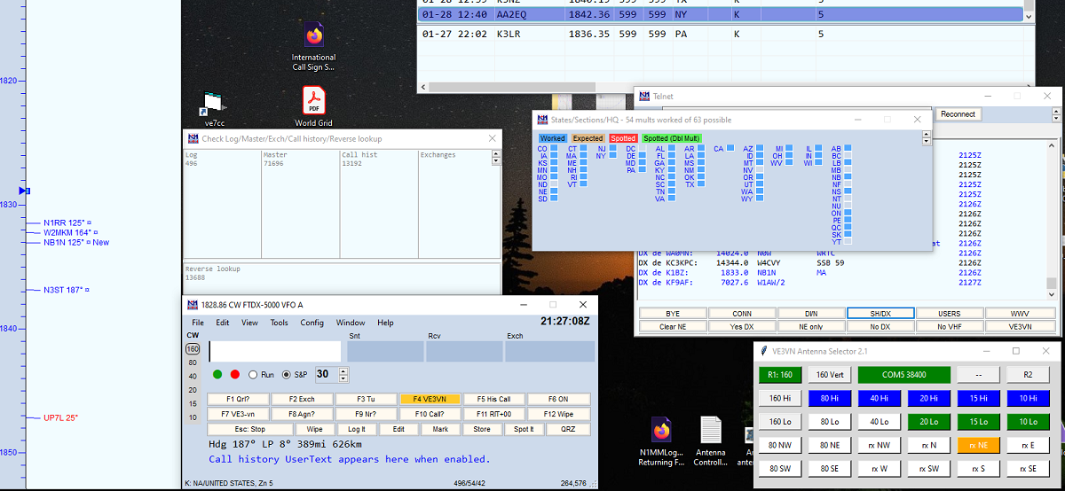
When I'm running stations I typically have my left hand on the keyboard and my right hand on the mouse. That way I am ready to type if I'm answered or to hunt for weak callers by clicking the Beverage direction buttons. Below is a closeup of the GUI. Design and operation of the GUI was fully described in an earlier article.

Eventually the buttons will be arranged around a great circle map centred on my location. That was my approach on the physical controller that I abandoned in favour of software. Making the GUI pretty is lower priority than getting it working. The same will be done with the 80 meter vertical yagi direction buttons on the left, which also now work. Since this was a single band contest, there is only one transmit antenna and no BPF (band pass filters) to deal with.
I wish that I had a software control to switch the FTdx5000 receive antenna feature. There is no generic way to do that since the CAT commands are unique to each manufacturer, and N1MM doesn't provide a generic interface for it.
It can be helpful in a contest to switch between receive and transmit antennas and, for that matter, change the pre-amp setting to equalize signal levels. Beverages are great but their signal level is low. Lucky hams with directional 160 meter transmit antennas typically use it for receiving except for particularly weak signals that would benefit from a higher RDF (receive directivity factor).
The GUI was a pleasure to use. It is easier and faster than twiddling knobs and switches, and I don't end the contest with sore fingers and wrist. Because it was easy I "tuned" in stations faster and I was more willing to hunt down elusive signals. That helped my score. I would often click on Beverage buttons 2, 3 or 4 times after every CQ because it was so easy to do.
No bugs were encountered despite continuous use over many hours. That's reassuring. The only glitch is one I knew about before the contest and it wasn't difficult to work around. The problem is this: when I click a button on my GUI, Windows transfer focus to my app and keeps it there. I have to transfer focus back to N1MM to type into its EW (Entry Window).
You can do it manually by clicking on the EW with the mouse. That's very inconvenient in a contest. While not a problem in this contest, when operating SO2R clicking on an EW alters the receive and transmit focus and the stereo behaviour of headphone routing. That's disastrous. There are Windows APIs to transfer focus less obtrusively and I added this to my software before the contest.
My method of transferring focus only works about 95% of the time. For the other 5% I need to click on the EW or click on another GUI button and hope that focus transfers on the second attempt. The latter was easier and always worked. Now that the contest is over I'll get to work on improving the focus code. The N1MM development team provided guidance on how I should do it.

You might think that having a bunch of clacking relays at my elbow would be annoying. To my surprise it wasn't. They are not so loud with headphones that fully enclose the ears with foam pads. It was reassuring to be able to monitor that everything was working as it should on this, its first use in a contest.
I may write an article on its construction. In case I don't it may be helpful to briefly describe what is shown in the photo at right. There are updates to the hardware shown in a previous article, with the addition of wiring and cables for the Beverages and 80 meter yagi.
The Arduino is powered by the USB cable. It is also powered by the external 13.8 VDC supply, using the 5 VDC regulator from one of the relay boards. When I go wireless and lose the USB cable, it will have the power it needs. Logic on the relay boards operates at 5 VDC but the relay coils require 12 VDC. I chose the boards for that reason.
I included polarity protection for the external power supply but no RFI filtering. So far the latter has not been a problem. In part this is because the antenna switch control lines connect via the relay contacts to the power supply, bypassing the sensitive logic circuits. That provides a measure of RFI protection, but no protection against lightning. The latter will require additional work.
I had to unify the grounds of the various DC circuits and keep inactive control lines open (not grounded) to avoid peculiar circuit behaviour. In one case a grounded inactive control line created a current pathway through tower-mounted equipment shorted the power supply. Lightning protection will, in most cases, require GDT (gas discharge tubes).
The vast number of control lines due to the large number of antenna switches in my station have to be terminated on the relay boards. I spent a lot of time with a crimp tool to make the Dupont connectors that plug into the Arduino GPIO jacks. There are daisy chains of relay connections for ground and 12 VDC to power low-side and high-side control lines, respectively. The many Cat5 cables are screwed to relay terminals and the other end soldered to DB9 and DB25 connectors. It's tedious and exacting work, and unavoidable.
There are at present no cables for the two sets of BPF. They will connect to the GPIO jacks at the bottom centre of the photo. This was deferred until I came up with a switching circuit that meets my requirements. Unlike the antenna control lines, these short distance connections are amenable to solid state switching and are largely isolated from RFI and lightning risks. BPF were not needed in the 160 meter contest and can be manually selected.
One curious problem arose when I wanted to shut the system down. Turning off the 13.8 VDC power supply did not release the energized relays. Coil voltages are nominal and they will operate over a wide range of voltages. The critical specs are the turn on voltage -- the minimum voltage for the relay to energize -- and the release voltage -- the maximum voltage at which the relay will remain energized.
The circuitry on the relay boards routes the 5 VDC regulated supply through the relay coil switching electronics when the external supply is disconnected, and 5 volts appears to be higher than the release voltage. I have to either cut all power to the Arduino or click buttons on the GUI to guarantee that all the relays are idle.
On to version 2.2
I must choose the final design for BPF switching and build it. That's almost entirely hardware since the software is already tracking the band and will bypass the BPF for non-contest bands. This must be built in the next two weeks if the automated system is to be used in the ARRL DX contest.
Once the hardware is substantially complete, it can be moved off the desktop. Software development only requires that it be accessible, not visible.
Successfully using the system in an actual operating event gives me confidence that I am on the right track. CQ 160 was a good choice since the demands on the system were modest, the benefit high and the risk was low since my participation was casual rather than competitive. There were no nasty surprises while logging 750 QSOs and many more CQs during 10 hours of operating.
No comments:
Post a Comment
All comments are moderated, and should appear within one day of submission.