Monday, September 30, 2019

One Step Forward

My one step back a few weeks ago continued to the point where I had just one HF antenna: the 80 meter vertical. This kept me off the air and focussed on rebuilding. The removal of almost every antenna was necessary to move and repair antennas in preparation for the next configuration of my antenna farm. It has been a very busy time.

With the help of friends I am again active on all bands from 80 through 10 meters. Until more antennas go up my flexibility is limited, so I cannot call this progress. That explains the title of the article. Over the next month there should be enough progress that I can truly claim that I have taken one step back and then two step forward.

For now it's just one step forward in which the station is different but at similar capability to what it was a month ago. In this article I'll run through the progress so far.

TH7: high tri-band yagi

I will have little to show for 10 meter antennas when this year's work is done. That is acceptable for the next year since signs of life on that band will remain elusive for at least that long. With a large tri-bander up at 43 meters this will give me flexibility during contests to target, say, South America at the same time as Asia on 20 meters. I am assuming my new 20 meter and 15 meter stacks on the new tower will be ready and I am working hard to make it so.


I really like this picture. The Hy-Gain TH7 dangles at the bottom of the tram line fully rigged and ready to be hauled over the hay field to the top of the big tower. Posing with the antenna is my trusty ground crew (left to right) John VE3NJ, Don VE3DQN and new ham Alan VE3KAE.

Notice how the antenna is well balanced so that the boom is level and the elements point straight ahead. This is the correct orientation to clear the guys and not strike the tower or mast. Those element tips are fragile. Two people lifted the boom as the tram line was pulled tight to prevent the elements from catching on the ground. Two people manually operated the haul rope during the lift. Power makes the job easier but increases risk of damage when the the antenna strikes an obstacle.

Many hams attach yagis to tram lines with custom made rigs that guarantee good orientation. I do it old style with ropes. With practice ropes work very well and allow for rapid removal and easy packing at the top of the tower, an important consideration. In this instance it worked beautifully as the close spaced driven elements of the TH7 slid right around the tower and mast.

One mistake I made was to point the antenna backwards. Although this is easy to correct by calibrating the prop pitch rotator controller the direction I dressed the cables and rotation loops is not compatible with a north centred rotation, which is the preferred method in this part of the world. I avoided rotation until it was fixed a few days later.

The TH7 was retuned to resonate lower in the band. SWR is a little higher than ideal at the low ends of 15 and 10 meter. but better than it was before. The boom is attached to the 3" mast using the same modification I used for the TH6. I shortened the DX Engineering saddle clamp on the top side to avoid it contacting the phasing line between the driven elements.

Other tri-band yagis

The reason the TH7 is up there and not the TH6 is because the close spacing of the driven elements does not easily permit tower side mounting. The TH6 is better for this. It was trammed to 75' and pointed roughly south to permit working Caribbean and Central American multipliers and the southern US, all of which are present during opening to Europe on the high bands. It uses the same side mount bracket as used previously for the Explorer 14.

The Explorer 14 is now gone to its new home where it will soon bring home the DX to its new owner. Although a small antenna it did well for me during the past several years.

The TH6 was inspected after removal from the tower. A couple of defects were discovered which I assume these were responsible for problems that began last winter. The worst was the poor design of the driven element clamps that connect wires to the balun and beta match line.

The tabs on the aluminum wraparound clamp bend when the bolt is tightened. There is no provision in the TH6 to prevent this so the wire studs don't sit flush against the tabs: they wobble. My antenna was particularly bad due to its great age.

I added two backing nuts to allow fine adjustment of the clamp pressure and squarely bond stud and tab. The TH7 is better than the TH6 in that it has one backing nut, but still not the two I used. The studs were weatherproofed after taking the picture since the tinning has deteriorated. The hardware is stainless.

I took the opportunity to move the yagi's optimum performance higher on each band. Previously it was set for CW so the SWR was poor at the upper ends of the SSB band segments. Not wanting to lose CW performance I opted to shift it slightly higher, just below the settings for "Lo Phone". Because there is only so much bandwidth possible with a tri-band trap yagi some compromise is necessary. Eventually the TH7 will be converted to a TH6 so the two can be stacked for added performance. The conversion is necessary to achieve a similar impedance and therefore good power division.

I made a mistake with the tram which at least doubled the time to raise it to its new home. The upper tram anchor and haul rope pulley were too close to the mounting position. Manoeuvering a big yagi in a stiff breeze with ropes getting in the way and pulling the antenna out of my hands was too much. We lowered the antenna and redid it properly. Expedience costs rather than saves time.

XM240 40 meter yagi

This small 40 meter 2-element yagi has been returned to its original location on top of the Trylon tower at a height of 21 meters. The lift went pretty well considering the necessity of dropping several above grade cable runs and navigating the long elements around the trees that have grown over the previous two summers.

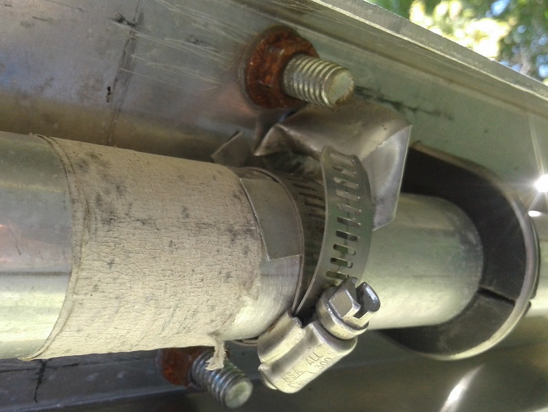
A few modifications were made to improve the antenna. The previous owner modified the antenna to make it more robust in extreme weather. He did a fine job of it but he should have chosen better hardware when he replaced the Cushcraft element-to-boom clamps. The cheap galvanized muffler clamps do not have enough grip to prevent the elements from rotating.

I inserted galvanized mesh under the clamps to provide mechanical texture to improves the grip. While not ideal I could not simply use better clamps such as the flattened and textured DX Engineering Cycle 24 clamp since there is no reliable sizing of muffler clamps and I'd have to drill more holes in the aluminum channel. Too many holes risks weakening it. Time will tell how this improvisation deals with the wind.

The other improvement was to ground the reflector element to the boom. This is a popular mod to reduce precipitation static by providing a path to ground for the static charge. Performance is not affected. Precipitation static was a serious problem at 150'. We've had one rainfall since the antenna went back up and...there was precipitation static, though not as bad as in the past. I'll continue to monitor.

I adjusted the rigging to ease attachment to the mast. Ideally two on the tower eases installation of this unwieldy yagi but I made do on my own by adjust the rigging and the procedure. The lift was done the same day as the TH7 with the same ground crew. I spent two days beforehand to prepare the antennas and rigging on both towers to best utilize the time of my friends.

In the picture I am in the process of attaching the mast clamps. There are a few interesting features of the rigging that are worth mentioning:
  • I attached the boom truss to the lift rope. This kept it out of the way during the lift, made it easy to slip onto the mast and by keeping it in one piece there is no risk of one end slipping out of reach while it is being assembled on the tower.
  • Long ropes are looped over each side of the boom. These tag lines allow fine control of antenna orientation in tight spaces. When done pull one end of the rope and it falls to the ground.
  • Precise positioning of the mast clamp needed to insert the clamps for an antenna this size is no easy task for one person. I used a couple of cargo straps as a third hand. I previously slipped all 4 clamps onto the mast and raised them one by one, top to bottom, for attachment. The rigging must keep the plate flush to the mast since there is nothing on the boom to grab onto to rotate it.
There are a few reasons for placing the XM240 at this new location. First, I need a directional yagi at intermediate height for contest work. Although side mounting it on the big tower is possible I do not have time this year to build a side mount suitable for almost full 360° rotation. Second, the Trylon is close to the house and there are many weak noise sources that are audible on 20 meters and above where the atmospheric noise level is low. This is not a problem on 40 meters. For long paths I have another plan for this autumn: a full size rotatable dipole above the TH7 on the big tower.

80 meter inverted vee

The 40/80 meter inverted vee that was on the Trylon is headed to its new (old) home on the 150' tower. However the 40 meter element of the fan dipole has been removed so that it's solely for 80 meters. It is no longer needed on 40 meters and it used to twist and tangle in the wind which would make it unusable on 40.


The tower mount has been improved from an ABS pipe to a steel angle bracket. The new bracket is far stronger and will take more tension. It is also a better mount for the balun (common mode choke). Strain relief for the wire legs keep stress away from the balun studs.

Modelling tells me the best pattern for short paths and low directivity is at a height at or a little above 30 meters. This will  also keep it well away from the other antennas on the tower. Unlike its original installation the two legs will go down into the tree line on the north end of the hay field, avoid ground anchors in the hay field. The model shows almost no effect on the pattern by doing this.

It should be a good antenna for the QSO rich northeast, mid-west and south-central US. After sunrise and before sunset a horizontal antenna often works better than a vertical on 80 meters on both short and DX paths. Unfortunately it's resonant frequency is ~3700 kHz, ideal for neither CW nor SSB. If widening the legs of the vee more doesn't help I'll lengthen it to lower the SWR below 2 within the range of 3500 to 3600 kHz. My primary use for the antenna is CW contests and DXing.

One step forward

Other antennas

With the bulk of the tramming on the 150' tower is done I deployed the radials for the 160 meter antenna and connected the over-ground coax. I kept the field free of trip hazards for the safety of the crew. The match is different each year I deploy this antenna. This year it resonated at 1800 kHz so I adjusted it to resonate at 1825 kHz. I believe the variability is due to the distance from the antenna from guy wires and the directions the radials run, neither of which are identical each year.

Work on the 80 meter vertical yagi is delayed. Since this antenna can be done by myself on the ground in the cold weather it is low priority. It's just a little frustrating that this project is taking two years to reach fruition. However I budget the time and energy I devote to amateur radio so that it doesn't become a burden. On the positive side it really is almost complete.

The last stage of aluminum work on the 20 and 15 meter long boom yagis is done. I have only to cut and insert the element tips, mount them on the boom, build gamma matches and raise them for tuning. October will be a busy month.

The mast bearing plates for the new 140' tower were assembled and declared unfit for use. I made an error in the template that requires modification in my workshop. This is a temporary obstacle. I expect to raise the top sections of the tower along with the mast and prop pitch motor by mid October.

When everything is completed I will be ready for the winter contest and DX season. Next year will be less busy with only a few large projects. More on those in the coming months. Right now I remain focussed on antenna building and becoming reacquainted with the HF bands since I did little over the summer other than 6 meter DXing.

Saturday, September 21, 2019

Relative Strength

Any ham with a tower or who has home brewed yagis will know there are a variety of software tools available to help with mechanical design. There are mast stress calculators to determine wind and ice survival of various grades and sizes of steel masts. Other calculators will determine stress on yagi booms and elements with attention to wind and ice loads. For the experts there are FEA (finite element analysis) engineering packages that handle most complex structures such as towers, both guyed and free standing.

Most of these tools are not used when buying commercial products. Instead we rely on manufacturer specifications and recommendations. Unfortunately some knowledge of various standards may be required since many advertisements attempt to place products in the best light and therefore choose to highlight specifications that may mislead even when accurate. Buying is not always worry free.

Guessing, optimism and hope abound among hams, including myself. I often calculate but other times times I rely on extrapolation from known designs and existing installations. If done carefully it can produce good results.

This is not an article about all those software and web tools for doing the heavy lifting for those mechanical calculations. Instead I want to discuss how I resolved a common question I deal with all the time when doing these calculations:
What happens when I change X?
X is a variable regarding a pipe or tube choice that may include but not limited to:
  • Strength: bending, axial or other load limit
  • Weight
  • Wind load
  • Cost
All have a bearing on the choice of boom, mast and yagi element structural members. It is helpful to play the game of What if? to see if the change is helpful or deleterious with respect to those criteria. Sometimes I choose pipes based on what best fits!

The relationship among those values can be complicated since, for example, reducing pipe diameter reduces strength and weight but also reduces wind load and cost. Trying alternatives can be enlightening, just like when using antenna models or electrical circuit simulators. Going by intuition and guesswork is faster but unwise. Using the engineering models spits out results but it is left up to the user to numerically compare among multiple scenarios.

As a design aid I use spreadsheets for calculations that may be inconvenient to do in other ways. Examples include: coils size, Q, wire length and inductance; transmission line impedance for wire diameter and spacing; wire coordinates under rotations for use in antenna models; and much more.

I wrote one for pipes, to calculate the parameters listed above. It compares two pipes to facilitate review and assessment. It makes it easy to discover the trend of pipe strength as diameter and wall thickness are varied. Wind force and pipe weight can change to a surprising degree. It's all excellent data to have in hand.


The first example compares two aluminum tubes of different diameter and the same wall thickness. Notice the better than 60% strength increase for a tube only 25% larger. Since the wind load increases in proportion to diameter the wind speed and ice survival is superior. Cost of large pipes and tubes is approximately in proportion to weight so this, too, is reasonable at 27%.

Notice that the spreadsheet doesn't calculate the actual strength of each pipe or the force for a specific wind speed and ice coating. There are ample tools available to do those calculations and I use them. This spreadsheet is a supplement not a replacement or consolidation. The spreadsheet assumes both pipes are the same alloy with identical strengths.

The spreadsheet works in English units since the large majority of pipes and tubes used in Canada are sized in these units despite this being a metric country. Industry inertia is strong, as is trade with the US. It would not be difficult to convert the spreadsheet to metric. The spreadsheet was calibrated using trade data for steel and aluminum pipe and tubes. Differences among alloys and tempers are negligible and are ignored.


The second example compares nominal 2-½" steel pipes, one schedule 40 and the other schedule 80. The heavier pipe is 26% stronger but weighs 32% more. This is poor economy. However on plus side the wind area is identical so the additional strength comes with no wind load penalty.

These first two examples illustrate the well-known rule that for a similar quantity of material (cross section or weight) it is better to increase diameter than wall thickness.


The final example compares a 2" schedule 80 aluminum pipe to a larger diameter 2-½" schedule 40 pipe. Again the thinner wall pipe of larger diameter is the better choice. Strength is 45% better for an increase of 21% is wind load and 15% in weight and approximate cost.

I don't always use the optimum pipe or tube, choosing to use what I have available or can acquire at a good price. The spreadsheet helps me understand the implications, in particular where I run the risk of poor economy. Ideally I should include alloy and temper in the spreadsheet to broaden the range of experimentation. Perhaps I will do so eventually.

Although I have not included the specific formulas used in the spreadsheet they are straight-forward to derive or look up. I extracted the strength calculation from a public domain beam spreadsheet. Surface area is simply length multiplied by diameter, after which you must apply the widely available wind load calculation for long cylinders. Circular cross section is the area of the outer diameter less the area of the inner diameter. Multiplying that by a constant gives the weight.

Sunday, September 8, 2019

One Step Back

Progress is not continuously upward. There can be setbacks and there can be planned retreats. At my station the latter is the case. I am taking one step back as a prelude to major progress

Before I can reconfigure the station and raise new antennas it was necessary to remove all the HF yagis from the towers. With the help of friends this stage is now complete. Unfortunately that temporarily leaves me with only 3 antennas: 80 meter vertical, 40/80 meter inverted vee and 6 meter yagi. That's it.

Since the next few weeks are not filled with major contests and rare DXpeditions, or sunspots, I don't expect to suffer too much. With low band activity just beginning to stir from the summer lull I have little incentive to turn on the rig. This leaves me to concentrate on tower and antenna work.

The TH6 and XM240 which just came down from the 150' tower are lying in the hay field. The tri-bander requires service since there is an intermittent, most likely located in a trap in the 10/20 meter director. The XM240 will undergo a few modifications but is otherwise working. I had suspected an intermittent connection this winter that instead is due to a relay in the 2×8 antenna switch and a loose N connector.


With the help of friends antenna removal using the tram line went pretty well due to two innovations: radio communications and anchoring the tram line on a large tree. All were overjoyed not to have to shout, whether from the ground or on the tower. Rigging the tram line on the top side is more fraught than lifting yagis due to the difficulty of testing and correcting the rigging.

Every job on the tower requires more effort than on the ground. With advance planning I managed to complete this job with just two climbs: one to prep the antennas and rigging and one to do the job and clean up. Even so my combined time on the tower was approximately 5 hours.


The XM240 was improperly rigged which caused the capacity hats to tangle the top guys. I had the guys haul the antenna back up so that I could correct my mistake. Better that than losing those fragile aluminum rods. Time lost was no more than 30 minutes and was well worth it.

At the bottom of the tram line I hacked a short distance into the bush and attached a winch to a large tree. I took the above picture after the winch was taken off the board but you get the idea. The long outrigger prevents the winch from being twisted by the steel cable which can rapidly devolve into a dangerous situation.

The rope you see is a safety line to prevent the tram line from collapsing if the winch fails or is mishandled. It is tied to a thimble on the bottom end of the tram cable. The winch cable is attached with a shackle.

With a bit of luck the TH6 and XM240 will be back in the air within a couple of weeks. I am half convinced to convert the TH7 into a TH6 so that these tri-banders can be stacked. A similar impedance curve is required for equal power division.

After trying a couple of different element tuning schemes for the TH7 I've concluded that the TH6 is better suited to my needs. Conversion involves removal of one driven element and the phasing harness, changing the length of the beta match stud, shifting a few elements along the boom and adjusting element tip lengths. It's pretty straight-forward.

For now either the TH6 and TH7 (or 6!) will go on top of the 150' tower for the winter season. The other will be side mounted at around 75' and fixed to the US south. That should cover all the short path openings to the US 4, 5 and 8 districts, and some of 7, 9 and 0. Eventually the TH6 stack will be rotatable between 150° and 270° for increased utility.

Now that I've taken a step backward it's time to take two forward. Apart from efforts to get these antennas refreshed and back up the towers I am now focussed on completing the 20 and 15 meter stacks this fall. That's a bigger challenge than taking down antennas. With a sprinkle of good fortune I'll soon have directional and multiple antennas on 80 through 10 meters.

Wednesday, September 4, 2019

Weighing Yagis

As I get closer to raising the stacks of 15 and 20 meters yagis onto the new tower I am increasingly sensitive to the mechanical challenges. Not only are they large size they weigh a lot. That is a primary consideration in the decision of how to accomplish the lift. Since I am far enough along in construction to weigh the antennas, albeit as a collection of pieces, I have done so.

Not surprisingly the booms comprise approximately half the weight of each yagi, more for the 20 meter yagis than for 15. The longer booms for the 20 meter yagis (12 meters or 40') and the heavier elements need to be stronger than the shorter 15 meter yagis (9.5 meters or 32'). Similarly the rotatable yagis at the top of the tower need to be stronger than the lower fixed yagis. The elements and element-to-boom clamps for each band are identical for both yagis.

Their measured weights are as follows:
  • 20 meter side mount yagi: 36 lb (16.5 kg)
  • 20 meter rotatable yagi: 60 lb (27 kg)
  • 15 meter side mount yagi: 25 lb (11.5 kg)
  • 15 meter rotatable yagi: 45 lb (20.5 kg)
I weighed them by subtracting my weight from the combined weight of me holding the boom. It is important to provide a solid and level support for the scale to achieve reliable accuracy. I took at least two measurements to eliminate method errors.

It is no accident that the booms for the side mount yagis are lighter. They are lower and thus subject to less wind stress, a concern since they have a larger surface area. In this case larger diameter does not mean stronger because for most of their lengths the wall thickness is less.

Next up were the elements, which I weighed in the same manner. There is some uncertainty in these quantities because of their low weight. Element-to-boom clamps are included in the weights.
  • 20 meters: 8 lb (3.5 kg)
  • 15 meters: 5.5 lb (2.5 kg)
The ratio is about what you'd expect for the wavelength ratio. Tube sizes are the same, following the same taper schedule, with shorter lengths of each on 15 meters. They taper from 1" down to ½". I'll have more to say about the element design and construction in a future article.

Putting it all together I can estimate the total weight of each yagi:
  • 20 meter side mount yagi: 115 lb (52 kg)
  • 20 meter rotatable yagi: 80 lb (36 kg)
  • 15 meter side mount yagi: 58 lb (26 kg)
  • 15 meter rotatable yagi: 85 lb (38 kg)
The weights include an allowance for gamma matches, boom trusses and boom-to-mast clamps which are not complete. The side mount yagis do not include boom-to-mast clamps since tower brackets are separately lifted and installed.

Lifting options

Antenna weight is the major consideration for choosing a lift method. Both side mount yagis are light enough to be trammed using my existing hardware. The 15 meter yagi is moderately heavy and the 20 meter yagi, although very heavy, is being lifted only halfway up the tower (20 meters high). The rotatable yagis are another matter. At 85 lb the 15 meter yagi is close to the limit I'd want to lift to 140' (43 meters) with my existing tram, and the 20 meter yagi is substantially heavier.

My choices are to make a stronger tram or to lift the antennas in pieces and assemble them on top of the tower. The latter is not as daunting as it sounds. It's a method used by many hams. I have the mechanics of the process thought through since when I eventually build my full size 40 meter yagi it will be lifted in this fashion. That antenna design is not yet complete but I have enough of the components to estimate a weight in excess of 200 lb (90 kg). A crane can do the job but at substantial expense.

Wind load and yagi survival

I have not done detailed engineering calculations to determine wind and ice survivability of these yagis. Instead I interpolated boom and element strength from documented designs to achieve my strength objectives. The only calculation I did was to estimate boom strength using software for simple beams with a load on the extremity.

The lighter side mount yagis have the greatest wind load due to being 3" diameter end-to-end. The booms of the rotatable yagis are lower diameter but with thicker wall to compensate. In general there is a greater strength benefit from increasing tube diameter than increasing wall thickness. However, the strength is not only adequate the lower surface area reduces the wind force and ice load.

Projected cylindrical surface areas for the yagis are as follows:
  • 20 meter side mount yagi: 10 ft²
  • 20 meter rotatable yagi: 8 ft²
  • 15 meter side mount yagi: 8 ft²
  • 15 meter rotatable yagi: 6 ft²
The elements are identical for side mount and rotatable yagis. Their wind surface areas are estimated as follows, representing an average since each element has a different ½" tip length.
  • 20 meters: 2.0 ft²
  • 15 meters: 1.25 ft²
Multiplying by 5 (each antenna has 5 elements) we get 10 ft² and 6.25 ft² for 20 meters and 15 meters, respectively.

Maximum wind load occurs when either the boom or elements are orthogonal to the wind direction, with a smooth and shallow dip between those extremes. Obviously the side mount yagis have to contend with whatever weather occurs while the rotatable yagis can be rotated to lessen the impact. Boom and element strengths must also be considered but I don't have those calculations yet.

I live in a 135 kph (85 mph) wind zone. Over the decades I've lived in this region the strongest wind I can recall peaked at 120 to 130 kph. At 85 mph the wind force on a long cylinder is approximately 20 lb per ft². Therefore the booms must withstand from 120 lb to 200 lb wind force (shortest and thinnest to longest and fattest) plus gusts and turbulence. Each element must similarly withstand 25 lb or 40 lb wind force, which sums to 125 lb or 200 lb per 15 meter and 20 meter yagi, respectively.

The booms carry the force from the elements and the sum appears at the mast and tower. For the side mount yagis these forces are well within the capability of my tower. The only significant concern is the rotatable 15 meter yagi mounted 3 meters above the tower on the mast. For my selected mast (diameter, wall thickness and tensile strength) initial calculations are favourable.

However you can never say never. Although I intend to pin down the survivability calculations that won't delay the project. It is more important that the yagis go up this fall.

Moving forward

With this data in hand I can confidently move forward with my plans to lift the antennas. The rotatable antennas will be turned with a prop pitch motor which is more than adequate to handle these behemoths. Tower plates for the motor and bearings are currently being machined in my workshop.

One difficulty is tuning the antennas. With the driven elements so far from the mast and tower that job could be more difficult than the lift alone. Tuning will require multiple lifts to a low height or a mechanism to rotate the antenna, without tangling guys, to repeatedly access the feed point. This, too, is being planned.

Big yagis look impressive up in the air but getting to that point is a lot of work! I still think it's worth the effort. That puts me in a small minority of hams, even among committed contesters.

Friday, August 30, 2019

Tower Alignment With a Transit

For structural integrity a guyed tower must be vertical and straight. Although perfection isn't required it is highly recommended to get as close as practical. Doing this job without proper tools is prone to error; you cannot rely on your eyeballs alone! Take the extra effort to do it right.

When I put up my first guyed tower I used what I called my poor man's transit. I later improved the usability of this technique by mounting the straightest pipe I could find in my bicycle repair stand. When carefully made vertical with a long level it held its alignment quite well. Or it did if the wind wasn't too strong! In this way I roughly aligned my 150' tower and my new tower up to the 120' level (it will be 140' when complete).

Standing (or, better, sitting) back from the pipe and sighting along the length of the tower is not as easy as it sounds. Freezing your body in one position is more difficult than you might guess. Go ahead and try it by keeping a close and a distant object in optical alignment. It's made harder by the distance difference for eyes that need corrective lenses and cannot focus on both objects at the same time.

I knew that the alignment of the towers was less than what it could or should be. One tell was that the towers were not parallel to each other. The error was no more 2" or 3" (5 or 8 cm) from top to bottom, which while not large and not a significant safety risk does offend my sensibility. A few of my ham friends call me a perfectionist, and that is not necessarily intended as a compliment.

A local tower pro after asking me how I aligned the towers offered to loan me his transit. It was an offer I could not refuse. When I was ready to do the job he handed me the instrument and suggested I search on YouTube for videos on how to use the thing.

A transit is a type of theodolite used in the building trades. Other than YouTube there are many resources on the internet that explain a transit's function, features and use. Here is one that is straight-forward and easy to follow.

I took the transit home, fiddled with it a bit and read the dreadfully poor manual. But that was enough to put it to use. Most of the features are not needed to align a tower, but can be useful to survey a plot of land for a new tower. It wasn't even necessary to turn on the power except to play with the advanced features in the comfort of my shack. Setting up the transit for tower alignment involves the following steps:
  1. Plunk the transit down in the field far from the tower.
  2. Level the transit.
  3. Point the telescope at the tower base centre and lock its horizontal motion.
  4. Rotate the telescope up and down to track deviation from a vertical line.
Sound simple? Well, not quite. Let's look at the process in more detail.

Levelling

This is the most critical step in setting up transit for use. It absolutely must be level. The method I was taught and that works well for me is as follows:

  • Extend the tripod to working height, but not so high that you can't easily see the levels. Point one leg towards the tower so that you have unencumbered access to the telescope.
  • Roughly level the tripod top by eye then firmly push the leg spikes into the ground (assuming you're not on bare rock).
  • Mount the transit to the tripod. Adjust tripod legs until the bubble level (bottom) is approximately centred.
  • Rotate the transit so that two adjustment knurls are at either side. Adjust the knurls to level the transit using the the linear level (top). Do it for each of the 3 positions, then repeat until the transit is level in all directions. You can usually get away with only being precise about the level for the one position where the telescope points at the tower if the only purpose is tower alignment. But don't get sloppy: get it level in all other directions as best you can.
You should periodically check the level as you work. Unfortunately you must repeat the process every time you move the transit, and that must be done many times during alignment. It goes faster as you become accustomed to the process.

Pick a spot

The best spot is directly opposite a guy anchor, and farther from the tower than its height. The first is to ease sighting of the tower and for left-right symmetry. The second is to keep the maximum telescope angle below 45° elevation for ease of use. Farther is better than nearer, although it requires more walking to and from the turnbuckles after each adjustment.

The best spot is not always available because of obstacles such as buildings and bush. Or the sun is behind the tower from that vantage point which makes sighting the tower difficult and dangerous for your eyes. An alternative is the place the transit behind a guy anchor, slightly offset so that the guys don't block sighting the near tower leg. This is shown in the adjacent picture.

When you do offset in this fashion be aware that your view of the tower is slightly rotated. The difference may be less than 1" but it will loom large in the telescope. Also, the pier pin will not be vertically aligned with the nearest tower leg. Keep that in mind as you read the section below on the alignment process.

Preparing the tower

The guys are under a lot of tension. When you adjust one turnbuckle the tension of other guys at that level and especially those higher can distort the tower in unexpected ways. It is advisable to loosen all the guys equally before starting. Obviously this should not be done when the tower is heavily loaded and a storm is imminent.

The guys should not be so loose as to be slack. In my case with 5/16" EHS guys the pre-load tension is a little over 1000 lb I reduce the tension to no more than 500 lb. Do it for all guys above the lowest guy set. Leave the full pre-load tension on the lowest guys. As alignment proceeds we want the guys above the set being adjusted slack enough that they cannot distort the tower due to excess downward force. Similarly we want the guys below the set being adjusted to be at full pre-load tension.

All that said, if alignment is for periodic maintenance and not the initial alignment of the tower you likely don't need to loosen the guys. This is because the expected lateral shift required ought to be small. For new towers I find that the initial eyeballing rough alignment can be out by several inches. With experience more than one guy level can be adjusted at a time and tension becomes less of a concern. Don't overestimate your ability and you won't make any mistakes.

Aligning the tower

Guyed towers are aligned from bottom to top. You start by aligning the lowest guy set and move upward until the top. Starting at the top or middle will only make the job more difficult so avoid the temptation. This point was impressed on me by several experts. Loosening guy tension before you begin, as recommended above, greatly aids this process.

With the transit in position and levelled aim and focus the telescope at the tower's pier pin or suitable centre mark at the base. The telescope includes a reticle to do this accurately. On my transit the reticle looks somewhat like the image at left. I found the double vertical lines useful for bracketing bolt holes and leg ridges.

There is a knob to lock the horizontal motion, so lock it when your aim is close. There will be another knob for fine adjustment (concentric with the lock control on mine). Swing the telescope up and check for deviation from vertical at the lowest guy station.

Estimate the lateral correction required. Loosen the turnbuckle on the side the tower leans towards, then tighten the turnbuckle on the other side the same amount. You can make a good guess at how many turns of the turnbuckle it'll take by noting the tpi (turns per inch) and doubling it (since there are two screws) and reducing the travel a bit due to the angle of the guys -- lateral motion per turn is less the higher up the tower the guy attaches; this is basic trigonometry.

For large offsets do it in steps rather than all at once. This is also good advice if you've never done an alignment before. A bit of lubrication on the turnbuckle screws helps. Turning a balky turnbuckle carrying 1000 lb of tension generates a lot of heat (and loud screeching) that can damage the threads.

When you're satisfied with the alignment do the same for the other two positions around the tower. You'll likely need to repeat the circuit once and possibly more for towers badly out of alignment. After aligning the guys at each level tighten the three turnbuckles an equal number of turns until you reach the required tension (approximately 10% of breaking strength). Use a suitable gauge that is calibrated for the guy cable you are using. If all is in order the tension should be approximately equal on all 3 guys.

Repeat the process for each higher guy set until done. You should check the alignment at lower guy stations as you go along since as each higher guy set is tightened it will place additional load on the tower that can accentuate any imperfections. Be on the watch for significant deviations since this can indicate a weak tower section or guy component.

Common difficulties

The alignment process is straight-forward but tedious. Having friends to help makes the job go much faster. I find I spend a lot of time walking between guy anchors and transit, time which can be eliminated by asking your friends to tighten/loosen turnbuckles while you operate the transit.

It is good practice to have the turnbuckle screws approximately half inside the turnbuckle to allow adequate room for future adjustment in either direction. I found that with each new tower my initial rough alignment when corrected resulted in turnbuckles at one anchor with too much screw and with too little at another anchor. Don't shirk correcting these problems.


If there is too little screw thread inside the turnbuckle or the turnbuckle bottoms out during alignment you'll need to detach the guy to reposition the screws. Use a winch or cable puller of sufficient capacity to relax tension on the turnbuckle, unwrap the guy grip, adjust the screws and reattach the guy grip. Tighten the turnbuckle until the tension on the winch relaxes and remove the winch.


Use a tensiometer to return the tension to what it was before. Then align the tower only adjusting that one turnbuckle. This is a good time to note that when you cut the guy cable be sure to leave a longer tail in case you need it after alignment and repositioning a turnbuckle. You can cut it closer after the alignment is complete.

If you are uncertain whether the grip is safe to reuse replace it; they aren't expensive. I will reuse them once, but not twice, and only when the strands are not distorted and there is lots of grit remaining. From my own experience and those I've spoken to in the business no one can recall a grip failing on its second use. Guy grips are tougher than they look. However none of this guarantees that a reuse failure cannot happen.

Between guy stations the tower sections may not track in a straight line. Assuming that this is not due to damage (corrosion, metal fatigue, failed weld, etc.) and the deviation is large enough it is worthwhile to correct it. The problem is typically due to a section splice in which the bolt holes on one or more legs were not properly aligned when bolted.

Correction involves slightly loosening the bolts so that the vertical force seats all the splice bolts in the same position. Unfortunately the opposite can occur in some cases. I've done it though I'll admit it makes me nervous. Just be very certain the deviation is not due to damage. Better, call in an expert to do or supervise the work. In a guyed tower damage or deviations are more dangerous the lower they are on the tower, which is opposite to the expectations of many hams.

Finishing the guying

Guy components will relax when first put under full tension. For example, grips conforming to the shape of insulators and thimbles. The tower will drift out of alignment within days. For this reason professionals return to a tower a few days or weeks later to redo the alignment. We should do the same. It is worth the trouble even if money must be spent to rent a transit.

When you are satisfied that the tower is properly aligned and the steel has settled into its final shape you should add safety cables to the turnbuckles at each anchor to prevent them from turning under load and keeping the tower upright if a turnbuckle breaks. Clean and paint them to keep them in good working order.

As part of station general maintenance check alignment at least once each year. Do not rely on adjusting guy tension alone since, while indicative of potential trouble, tension changes don't tell you what has specifically happened.

Friday, August 23, 2019

Stacking Scenarios for the New Tower: 15 and 20 M

As I grind my way towards completion of my stacks of 5 element yagis for 15 and 20 meters it is time to decide what goes where. The objective is to maximize performance, when used as a stack and when used individually. The major decisions on placement: height and separation.

There is also the matter of interactions with yagis for the other bands and with the guy wires. For the present exercise I will ignore those interactions since the way I broke up the guys to be non-resonant and with sufficient yagi separation the pattern impact will be small.

In addition to electrical considerations there are physical constraints:
  • The yagis atop the tower cannot be separated by more than 3 meters (10') to keep mast stress within reason. Similarly the smaller yagi for 15 meters will go at the top of the mast and the 20 meter yagi at the bottom of the mast.
  • Lower yagis must be above a guy set, but not too far above to avoid tangling with the guys further up. The constraint is tighter if those yagis are rotatable rather than fixed. At least t his year they will be fixed towards Europe.
When completed the tower for these antennas will stand approximately 133' tall (40.5 meters) and the mast will rise another 10' (43.5 meters). Guy stations are nominally at 30', 65', 100' and 135', however due to section overlap the heights are more like 28', 61', 93' and 128'.

To recap the yagi dimensions:
  • 15 meters: 5 elements on a 32' boom (10 meters). This antenna has low SWR across the full band and has been optimized for best gain while having a good match and F/B. Design details can be found in an earlier article.
  • 20 meters: 5 elements on a 40' boom (12 meters). This antenna is a minor optimization of the yagi having the same dimension in recent versions of the ARRL Antenna Book.
Modeling is done with EZNEC. I use dual sources for in-phase stacking rather than phasing harnesses to make the modelling exercise easier. This does not materially affect the pattern but does affect the impedance, and the latter is not the focus of this article. SDC (stepped diameter correction) is used for all elements per my tapering schedule. Construction detail will appear in a future article.

If you're new to stacking you may want to review my article on the basics of stacking. There are of course many other resources on the topic of stacking around the internet and in the amateur literature.
20 Meters

I'll look at 20 meters first since the stack is more constrained; that is, there are fewer viable options for placement of the yagis. The upper yagi is at the bottom of the mast, which I waffled on with regard to the precise height, as you can see in the plot traces. The 2' (0.6 m) different is negligible. The lower yagi is in the vicinity of guy stations, ideally slightly above as discussed earlier.

Height of the upper yagi is ~2λ. Height of the lower yagi is at either 1λ or 1.35λ. The modest difference in height of the lower yagi has a significant impact on the stack behaviour.

The respective separations are 41' (12.5 m or 0.6λ) and 67' (20.5 m or 1λ). The first is equal to the boom length, usually considered the minimum separation for good performance; this is discussed in more detail below. The second is well separated at the cost of placing the lower yagi relatively close to ground (1λ).

The lowest lobe of the upper yagi is 7°, and 11° or 15° for the lower yagi. Lowest lobe of the stack is 8° and 9°, respectively.

Gain of the stack and individual yagis varies by less than 0.4 db for the two scenarios. This is indicative of low interaction, and that is confirmed in the EZNEC model. Although not confirmed in this exercise the low interaction (mutual impedance) between yagis promises low pattern distortion when they are pointed in different directions.

Stacking gain over the individual yagis varies from 1.5 to 2.5 db, which is quite good for 20 meters at these heights. The nominal 3 db stacking gain is just that: nominal. There are many variables that determine this performance metric.

Notice that the patterns of the lower yagis differs quite a bit due to their different height, and this affects the pattern of their respective stacks.
  • Vertical radiation is higher for the lower yagi at 92' since that is the only position that is not a multiple of λ/2.
  • Inter-lobe nulls coincide more closely when the stack separation is smaller, as expected. Better elevation angle diversity is achieved with greater separation. That is desirable for paths with an elevation angle close to a null so that we can avoid dead spots. 
  • The major lobe of the lower yagi is significantly higher at the lower height. This, too, is desirable for path diversity. When fixed to Europe with its wide range of probable elevation angles the lower yagi becomes more useful.
  • High angle minor lobes are attenuated with the lower yagi at 1λ height.
The choice for 20 meters is quite easy. The lower yagi will go directly above the second guy station. When (if) the lower yagi becomes rotatable it will also perform well on paths to Africa, Caribbean and North America.

15 Meters

With the upper yagi at the top of the mast and the shorter wavelength it is easier to achieve low interaction between yagis on 15 meters in comparison to 20 meters. The shorter boom length is also helpful in this respect.

The maximum height possible for the lower yagi is below 120', otherwise the elements get dangerously close to the top guys. I therefore chose this height for the first test case since while not physically practical it highlights a too small stack height of 20' (6 m or 0.42λ), which is less than the boom length.

In the second case the lower yagi is at the more practical height of 100', a little above the second highest guy station. This maximizes the distance from the outermost elements to the upper guys. The stack height is 40' (12m or 0.85λ). This is much better spacing.

When modelled the difference in performance is readily apparent. As with the 20 meter stack the greater stack height there is better distribution of the elevation nulls, reduced high angle radiation and greater stack gain.

If I had a tower dedicated to each band I could exploit the height to add a third yagi to the stack. This is not practical in my case where 15 and 20 meter yagis present since optimum and equal spacing would have yagis tangling with the guys or parked too close to a yagi for the adjacent band. A friend of mine who does manage to have a 15 meter 3 stack shared with 20 meters uses a taller tower than mine.

My next test case was to move the lower yagi even lower, though not too close to the lower 20 meter yagi at approximately 68'. The chosen height of 80' is, like 120', risky since it places the outermost elements close to the next highest set of guys.

The result is a mixed bag. Rearward lobes are small but there is an increase in radiation at high angles. Differences in gain of the stack and individual yagis compared to 100' are negligible at less than 0.3 db.

My tentative choice is to place the lower yagi at 100' or a little lower to increase distance to the upper guys while not getting too cozy with the set of guys immediately below.

Other antennas on or near the tower

Interactions limit further use of the tower. I plan to use my TH6 and TH7, possibly stacked, at lower heights for short paths such as the US and Caribbean. There is no good place for these tri-band yagis on the tower that would not impact performance due to interactions with at least the lower 20 meter yagi in the stacks. The tri-band yagis will therefore go on the other big tower, well below the 40 meter and 10 meter yagis.

I would like to leave open the possibility of a wire 40 meter yagi pointed at Europe, strung on a catenary between the big towers. With 5 elements the wire yagi would be 30 meters longs, which is about half the distance between the towers. Interaction with 20 meter yagis should be managable. Impacts on the performance of the 15 meter yagis could be more severe. The same is true of the tri-band yagis which are, of course, resonant on 15 meters.

I am looking at alternative placements of the wire yagi to best advantage. There is modelling work to be done.

Vertical antennas for 160 meters are less concerning due to the polarization difference. However the T-top of my current 160 meter antenna will require a close look to confirm that it will not causing any problems with the yagis on both towers.

Yagi separation vs. boom length

There exists a rule of thumb that two yagis in a stack should not be closer together than the yagis' boom length (for identical yagis). This is good guidance even if it obscures the reason for why it is a useful rule. Without delving into excruciating detail we can dig a little deeper for some insight.

But first let's review how a stack develops gain. For two identical yagis fed in phase, in free space and far enough apart that the mutual impedance is negligible, the stacking gain is exactly 3 db. This fact alone is a curiosity since we are dividing the power so that each yagi get half of it and the yagis' far field patterns sum in the far field. Fortunately I wrote an article on how this is possible if it seems paradoxical.

In the real world the yagis interact with real ground and there will always be some mutual impedance between the yagis. The closer together the greater the mutual impedance since the various elements will have near field coupling to those in the other yagi.

It is possible to have stacking gain greater than 3 db with carefully engineered close spacing. However this is only advisable if the yagis always point in the same direction, whether fixed or rotatable. Otherwise when one of them is turned the high mutual impedance will distort the patterns of both yagis. In general it is a poor idea.

Ground reflections for the two yagis place their lobes and nulls at different elevation angles which affects stacking gain. By closely spacing the yagis the lobes, especially the lowest main lobes, will reinforce each other and give close to the theoretical but nominal 3 db gain. This is at the price of a reduced ability to sidestep elevation angle nulls since these, too, will coincide, as we saw in the discussion earlier in the article.


With the preliminaries out of the way let's return to yagi separation and coupling. Yagi gain increases with boom length. Gain comes from a narrowing of the main lobe. As the lobe narrows the mutual impedance to a vertically separated identical yagi decreases. This is due to field cancellation away from the main lobe, directions which would intersect elements of the other yagi. Note that for this purpose we are primarily concerned with the free space elevation pattern (shown on the right).

However the lobe narrowing happens in concert with a longer boom length. Therefore the angle of, say, the -6 db point is lower but will still interact with the outermost elements of the other yagi because they are further out. The relationship is not exactly proportional but close enough that the rule of thumb is justified: increase the separation as the boom length increases to achieve approximately the same amount of element coupling (interaction).

Keep in mind this is a minimum distance not an optimum distance. When you allow the yagis to point in different directions more separation reduces pattern distortion. This is usually a better choice than trying for maximum stack gain.


Refinement

I have ample time before winter to refine the stacking arrangements. This can be done in parallel with the construction and tuning of the four yagis. Although I had hoped to be further along by now I am getting closer. It's been a learning experience, one with unexpected stumbling blocks.

You can see from the picture of aluminum shavings (the dark patches are steel) filling most of a 5 gallon pail that I have not been idle! Construction of the yagis is a story unto itself and will be covered in future articles.

Sunday, August 11, 2019

6 Meter Season Wrap-up for 2019

We are now into 6 meter withdrawal season. This is the time of year when Es (sporadic E) openings rapidly decline in number and distance yet aficionados cannot quite let go. All I hear now on FT8 is endless CQing from those within direct or tropospheric propagation (within ~500 km). Although there is still some DX to be found if you are patient the season is effectively at an end.

This is a good time to reflect on my accomplishments this season and what I've learned. I did a similar season end report last year.

DX

Purple is my favourite colour
I ended last year with 56 DXCC countries on 6 meters using FT8. I tally countries separately from other modes to track my progress. Official counting methods mean little to me since I do not chase DXCC awards. As I write this I have worked 15 more countries this season for a total of 71 DXCC countries on 6 meter FT8. I don't believe there are any countries I've worked the last few years on CW and SSB but not on FT8.

I heard many more countries than I worked. That's the nature of 6 meter propagation. Of note I worked Japan for the very first time on 6 meters, using any mode. These QSOs were my first with Asia. With respects to continents only Oceania still eludes me. I heard several Hawaii call signs this year but all were in the continental US. American call sign practices can be frustrating to the DXer. I know the path exists since several hams in this corner of the continent worked Hawaii this year.

In my season's end article last year I noted that I worked 40 European stations on August 4 during an amazing multi-hour opening. Perhaps more amazing is that I broke that mark this year, working 43 Europeans on July 20. My European distance record now extends to Ukraine. Even so I have heard but failed to work many European countries such as OH, LX, 9H, LZ, YO among others.

I was unlucky with African openings apart from adding CN and EA9. I heard 5T5PA a few times, though very weakly and never workable. Better was 6W1TA who had a fine strong signal for almost 2 hours one day. In this instance I caught the opening near its end and failed to make it through the large North American pile up.

Looking south I worked HC5VF for a new one. CP1GJ was heard but not worked. Many stations were worked in northern South American and Caribbean. One that was active but not snagged was P41E.

My final country for the season was CY9C. In this case I got lucky since many others in this region had difficulty despite the relatively easy single hop path. You win some and you lose some. It would be no fun if every station heard is worked.

50.323 MHz

What seemed to be a great idea to move intercontinental DX activity to its own FT8 window is not working out. There was little to be found there this year. I did QSY to the DX window when domestic contest activity crowded me away from 50.313 MHz but with no success. The DXers, here and abroad, wouldn't move even when the QRM became overwhelming.

CW and SSB

The digi-averse die hards are still on conventional modes. The only significant operating I did on CW and SSB was to use those modes exclusively during the ARRL June VHF contest. Unlike my experience in 2018 this year I had far better success. With only a little effort I managed well over 100 contacts, reaching as far as the west coast. There are still signs of life at the low end of the band!

Despite my almost 100% focus on FT8 for DXing I have not used it in a contest. Perhaps I never will, but you never know. It's too slow and mechanical to hold my interest.

FT4

I have yet to use FT4, restricting myself to occasional monitoring. The 6 meter window is 50.318 MHz. It is certainly fast enough to interest me but I don't know if it'll catch on for DX work. Certainly it has promising attributes for 6 meter DXing. Maybe I'll try it next year.

Decoding sensitivity

There is an ongoing debate regarding FT8 decoding success rate between WSJT-X and alternative software branches, in particular JTDX. This may very well be true. What gives me pause is a few of the methods JTDX uses: correlation to known or expected messages and correlation to a data base of known active calls.

I am still thinking about whether this is a good idea. There is a fuzzy line between viable decoding and guessing, and I am ethically opposed to the latter. Even when I use Super Check Partial (SCP) during contests I always request a repeat or confirmation of the call.

Until now I have been happy to do no more than tweak upward the aggressiveness of WSJT-X decoding, yet even it does a bit of guessing. Where should the line be drawn? I don't know. As time permits I will download and experiment with JTDX on HF, listening only, to learn what it can do and how I feel about it. In the 2020 sporadic E season I will likely run higher power and I can expect more weak callers and therefore have greater need for decoding sensitivity.

Improvement is possible beyond the software. I have altered how I set up my rig and computer to better match the dynamic range of the receiver and sound card ADC. While preliminary results are ambiguous it looks promising. I may have more to say about this if I learn something of substance.

It is unfortunate that WSJT-X calculation of signal reports is not usable for determining signal levels, SNR or receive performance since it is relative to other signals and noise within the pass band. I only learned this recently. It explains some bizarre disparities between received and sent signal reports that I've witnessed.

Transmit quality

There is more activity on 50.313 MHz than ever before. Getting on is easy since every modern transceiver has 6 meters and many HF amplifiers include 6 meters. If you use RTTY or other data modes (or you do SSB contesting, like I do) you already have the required audio connections to your computer.

The trend may continue for the next two years until the solar flux edges upward and thoughts return to HF. I may be responsible in my own small way by encouraging local activity (FN25 and adjacent grids) during several talks I gave to local clubs last winter.

Unfortunately it is all too easy to transmit a dirty FT8 signal and its incidence is increasing in proportion to rising activity. Monitoring your own signal quality isn't easy and few bother to make the effort to do so. Most rely on recommended practices but without feedback don't realize when they've done it wrong.

I got more serious about it this year. With the help of a buddy we transmitted back and forth while tweaking our rigs to see what works best. I am now reasonably confident that my signal is clean. Over the winter I will build a test system so that I can monitor and make adjustments on my own. Perhaps I'll write it up if it looks to be useful to others.

The adjacent screen capture shows an FT8 signal with adjacent images that are often decoded. These are not harmonics. The DSP and equalization circuits in modern transmitters create novel difficulties. These images are present on far more FT8 signals than is good for peaceful coexistence. I get them on my own signal under some conditions and I want to make further improvements.

W9MDB has written a document on setting up your transmitter that looks quite good to me and explains a few peculiarities I've run into. Some surely need the lesson since there are too many signals far worse than is seen in the spectrogram above.

Improving QSO throughput

One of my objectives this year was to improve the number of QSOs I can squeeze into a shorter time. The key to this is understanding the software in greater depth and making liberal use of auto sequence features. The difficulty is understanding what auto sequence does in the critical crossover between one QSO and the next.

I have had good success once I let the software free to do what it thinks is best. It does always work out, and in those instances you simply need to be paying close attention and quickly alter the message or the station you are responding to. In short DX openings, with all their QSB, it is possible to interleave QSOs when one is interrupted by propagation or QRM yet be able to complete it a minute or two later.

There is much more to be said on the subject so I won't dwell on the topic now. I believe it is worthy of its own article. There is always more to learn about the subject and it is possible that many readers will benefit from knowing more, even veterans of digital modes.

Looking forward

As I've said before it is very likely that I'll have a 6 meter capable kilowatt amplifier next year. That is perhaps the biggest change I am planning for the near future. Once my HF antenna farming matures I will pay more attention to VHF. This includes an improved antenna of some kind and antennas for 2 meters and 70 cm. That's the upper limit of my interest.

With regard to other digital modes I have ventured back into MSK144 for the Perseid meteors. I haven't worked much, just playing with it to get more experience. Meteor scatter is something that interests me more for 2 meter use; on 6 meters the distance is easily spanned using more common ionospheric propagation modes.

Of more immediate interest is HF. Now that the peak sporadic E season is over there are antennas and towers to build and get operational for the fall and winter season. It also severs an inconvenient and invisible tether to the shack that keeps me from antenna work.

Tuesday, August 6, 2019

Draining Tower Static

We are all familiar with lightning, in which charge moves between ground and the atmosphere. There is less familiarity with the role that static plays on our towers and antennas. Charge doesn't move until the potential is large enough to bridge the distance from a location with a different charge. This static discharge can play havoc with reception. It is better to continuously bleed the charge so that its potential remains low. The best place to move that charge is to ground.

Let's begin with a story. Many years ago I visited a friend who was doing work on his modest suburban tower and antenna system. As is quite common during autumn in this climate there was light snow falling. As we were chatting we could hear a periodic snap sound coming from the doorway to the basement shack. We walked over to see what it might be.

Lying on the desk was the disconnected coax for his VHF yagi located about 15 meters up the tower. As we were looking around for the source of the sound a spark jumped across the coax connector. The snow was depositing a charge on the antenna which increased until the potential was enough to jump the gap and the charge would flow to ground via the coax shield. We could reproduce the spark at will with a screwdriver to reduce the gap with a wait of perhaps 15 seconds. At the time I was surprised this could occur with such a small antenna at a modest height.

Ordinarily the charge would be constantly bled through the receiver front end or a grounding style coax switch. When drained in this fashion the potential cannot rise high enough to cause any damage. But it would be unwise to plug the coax into the rig when there is a static charge present. Better to wait for the weather to settle.

A tower has a static charge on it due to its height despite being grounded. The ability to bleed the charge to ground can be difficult due to the potential gradient and the potential of the ground surrounding the ground rod. Although you cannot directly experience it there is a charge gradient along the tower, and indeed right up through the atmosphere. Just as there is no absolute protection from lightning the same is true of static charge, but the risk can be reduced. Our main concern is with reception. In extreme environments (high and very dry) transmission can be a problem but rarely at amateur power levels.

The Cushcraft XM240 40 meter yagi has a couple of inherent challenges with respects to static charge:
  • Elements insulated from the boom
  • Small diameter rods in the capacity hats
The former impedes the flow of charge to the boom and from there to the tower and ground. The latter increases the risk of corona and therefore more energetic discharges. Many hams connect the reflector element to the boom to permit charge flow. This has negligible effect on the resonance of the element. Although the driven element cannot be connected to the boom there is at least a long path to ground via the coax and into the shack.

I am motivated to do what I can since the static discharge noise on 40 meters can be dreadful when it is raining and sometimes when it is snowing. It is bad enough that the static discharges can be heard on nearby antennas for other bands. The XM240 is at particular risk of static charge since it is at the top of the mast. If it were completely bonded to the mast and tower to bleed the charge the QRN ought to be greatly reduced, protecting reception with it and antenna further down the tower.

Which brings us to the next difficulty: continuity between the mast and tower. If you've never thought of it before this may seem a strange question. Most would assume there is an electrical path between the mast and tower due to all those set screws and clamps holding everything together at the bearings and rotator. The problem is that electricity is being asked to conduct through bearings, which due to surface grease on the rolling components may not have reliable metal-to-metal contact.

The routine solution is a flexible wire between the tower and mast. Think of it as an insurance policy against poor continuity through the bearing surfaces. It might not help but it might help a great deal.

During a maintenance climb up the 150' tower several days ago one of my tasks was to install just such a wire. As you can see it's very simple. I cut a 2' length of heavy gauge, multi-strand speaker wire that was handy (though unlikely to be UV safe) and fitted ⅜" tinned lugs at both ends. One end connects to the tower via a top plate bolt and the other end conveniently fits onto a galvanized muffler clamp already on the mast. I was going to use the stainless hose clamp (visible in the picture) but I saw an opportunity and took it.

Will it help? I'll find out soon enough. I will need to see how it performs during rainfalls in the coming months. Unfortunately the insulated XM240 elements could muddy my observations. In any case the XM240 will come down soon and this time around I'll remember to ground the reflector to the boom. The "to be determined" antenna that will replace it at the top of the mast (46.5 meters high) will be bonded to the mast.

If the strap works I will do the same to my other towers. The fix is simple and justified even if the data of its performance is inconclusive.

Wednesday, July 24, 2019

Summer (blog) Vacation

I'm still here. New blog articles are slow to appear because I am very busy with antenna and tower projects, 6 meter DXing and a large number of non-ham summer fun stuff and chores. I thought I would fill the blogging gap with a progress report of sorts so that regular readers don't think I've vanished. I haven't. Regular blogging will resume, eventually.

To give you an idea of what I am up to I've listed the most important projects below. From this you will get an idea how busy I am. All will be written up in future articles as each project is completed and I have the time. But right now the weather is too good to waste. I have not provided links to articles which discuss these projects so if interested try the search box.
  • The 80 meter vertical yagi is near completion. The parasitic elements are tuned and the switching system is operational, as is the control head in the shack. What's missing is the control box containing the switching matrix, cable interconnections and switchable L-networks. It is partially built and I have all the parts.
  • Options and specs for the mast and rotation system for the new 140' tower have been discussed with my local machine shop and I should have the fabrication complete in the first half of August. I will be using my spare prop pitch motor as the rotator.
  • One boom left to be built for the 2 × 5-element stacks of 20 and 15 meter yagis. That one requires machining of a 20' long pipe the machinist can't handle in his shop. But it'll get done one way or another.
  • I have fabricated 2 sets of 5 element-to-boom clamps for those yagis. The rest are awaiting an order of fasteners to make drilling templates.
  • All the aluminum for the 20 yagi elements (4 × 5) is on hand and the bulk of the machining is complete. Once that is done the sections will be joined and yagi construction and testing should begin around mid-August. Elements have been scaled in software for the taper schedules that I settled on.
  • Design of the elements for a forthcoming full size 40 meter yagi is proceeding. I hope to at least get one complete element in the air as a dipole for testing over the winter to see how it performs electrically and mechanically.
  • Tower maintenance is ongoing. This includes patching surface rust, vertical alignment and checking of all hardware. Repair of malfunctioning antenna requires getting them down using the same tram line used to put them up them.
Reading the list is fatiguing enough, yet these are things I have to get done in the next few months.

Haying on my land should be complete this week and I will have more freedom to work on towers and antennas. This includes malfunctioning yagis that need to come down for repair or to be moved to a different tower.

I hope the weather is as good where you are as it is here and that you, too, are making progress on your station projects. Soon enough the weather will turn cool and the race will be on to complete work before winter settles in. Then I will have the pleasure of cold weather projects such as low-noise receive antennas and shack equipment. It'll be a while yet before I can truly relax.

Tuesday, July 9, 2019

Working Japan on 6 Meters

From my start on 6 meters in the mid-1970s, to the tremendous solar maximum of 1989-1990 and into the modern era of FT8 it is interesting that I had not achieved WAC (Worked All Continents) on the magic band. The one continent that confounded me was Asia. I came very close in 1989, eking out several partial CW QSOs with Japan. That was my sole shot since almost all of west Asia, like most of Europe, did not have a 6 meter band at the time.

With FT8 prospects improved, despite the lack of sunspots. Sporadic E openings to Japan and the Far East from eastern North America have been known about for a long time but due to their fleeting nature have only rewarded the most dedicated 6 meter aficionados both here and there. These openings are easier to catch with FT8 since all activity is captured by the software. This is what I've coined the discovery problem which FT8 solves so very well.

Historically it is known that the probability of an opening between Japan and northeastern North America peaks in the last week in June between 2130Z and 2300Z, our late afternoon and early morning in Japan. In fact the times between this daily window and their sunrise and our sunset are nearly equal. Although that may be nothing more than a coincidence it is nonetheless interesting.

To my chagrin I missed a fantastic opening in late June last year, the first year that I and most of the 6 meter community were on FT8. It was dinnertime and by the time I discovered what had been occurring the opening was ending. Sitting in front of the rig every day during the propagation window is not realistic, nor very enticing.

This year I was not so complacent. I really wanted a QSO with Asia, and openings to the Middle East have so far yielded no QSO. So I monitored, watched and waited for another opportunity to work Japan.

Statistically speaking I would likely have one or two chances, each lasting no more than 15 minutes. This would be terribly daunting were it not that it is early evening when I am more likely to be in the house. But this time I would have to pay close attention to activity.

During the second half of June there was no workable opening to Japan from this QTH. Others to the south, west and east had better luck. Other than a couple of decodes of very weak signals nothing was workable here in FN24. That changed in July.

The first opening arrived on July 2. Unfortunately it was only JA7QVI who was sporadically copied over a period of 10 minutes. Several other likely but very weak signals that appeared on the spectrogram did not decode. I called him without any luck. This isn't surprising since he is a big gun who typically runs QRO and his weak received signal boded ill for my 150 watts.

Success had to wait two more days. On July 4 signals were being reported by others in this part of the continent as early as 2200Z. I did not hear any QSOs being completed but clearly something was brewing. A strong opening to OX was on the wane at that time and the Nunavut beacon VY0SNO/B was widely heard. It was a challenge to monitor the band while cooking the evening meal! Happily the real fireworks waited until meal preparation was completed.

When signals began decoding I noticed that more were stations calling KL7HBK. Alaska's bearing is only 10° west of the Japan path but I never did copy him.

JE1BMJ was calling CQ NA but I couldn't get through to him as he faded in and out for several minutes. None of the other stations heard were decoded more than twice.

They say that patience is a virtue, so I made a sacrifice by eating my dinner in the shack. I watched and hoped for signals to grow stronger. Of course I was not quite that patient so I filled the silence with my own CQ JA.

As you can see in the screen shot that eventually signals did rise. A few decibels made all the difference. First in the log was JH1IFS. Then for a few short minutes I was the object of a small pile-up. I worked just 4 stations before the opening faded, but even one was enough to leave me delighted. During the fade I made a couple of partial QSOs as signals briefly rose out of the noise. Within 10 minutes they were gone for good.

It is interesting that I never heard the KL7 the JAs were calling and big guns only a few hundred kilometers from me appeared to work nothing in this opening. This is a great example of the spotlight nature of 6 meter openings. The spotlight narrows as the path length increases. All those points of intense E-layer ionization must line up in space as well as time to make the QSO possible. That's part of the attraction, working with what nature tosses our way to put the magic in the magic band.

Notice that every Japanese station calling me skipped message #1 in the standard FT8 sequence and used RR73 rather than separate RRR and 73 messages. That is an excellent practice for fleeting openings. They can be so short that the 30 seconds saved is critical to success. It also allows for more QSOs to be made by everyone during the opening.

I suspect the Japanese operators are acutely aware of this since almost all their DX QSOs on 6 meters are on paths of this type. Once you miss out on some juicy DX using the standard (and longest possible) message sequence you quickly learn. Exchange of grid squares is nice but is not necessary. The minimum required information for a valid QSO is call sign, report and confirmation of both.

Afterward I sat back and contemplated this achievement. It was one more of persistence than any particular skill. Sometimes that's all it takes. Just as in contests the one under-appreciated difference between the winners and losers is BIC: butt-in-chair. That was perhaps the most important factor that put these rare QSO into my log.

Technically I now have WAC worked on 6 meters. However I restarted my DXCC count when I returned to the air in 2013, on which basis I still need Oceania. My best shot for that is a Sporadic E openings to KH6. From here these are rare but certainly workable, perhaps no worse than Japan but with fewer active 6 meter operators. I've had a few false alarms since with US call sign portability the only KH6/AH6/WH6 stations I've heard were within the continental US. However I know that some in this region have worked Hawaii this season.

Returning to the topic of spotlight openings, these openings to Japan, Hawaii and other distant locales cannot be so unique. There must be many more similar openings to the unpopulated or lightly populated expanses of the Pacific Ocean and northwest Asia. Without active stations those openings remain undiscovered. Certainly there are other islands and UA0 is hardly empty, but the population density is low and the ham density is lower still. We need a confluence of rare conditions and a dedicated group of hams attuned to the nature of 6 meter propagation.

Calling CQ into a silent band is not a bad strategy even though there is rarely a reply. Somebody has to CQ, so why not you? It may be a rare occurrence but every so often a strong DX signal will answer. Sporadic E DX propagation has existed for many millions of years and will continue long after amateur radio is just a memory. It's up to us to appreciate this gift and put it to good use.