In this article I'll step through my design and construction of a mast that suits my needs. For this tower it is more involved than popping a short pipe through a bearing into a rotator and mounting a small yagi on top.What I came up with is not ideal yet suitable to my needs. Part of the challenge was making it compatible with the prop pitch motor/rotator with its chain drive.
Pipe mating
I am fortunate to have acquired two prop pitch motors and a chain drive system custom designed for my LR20 tower. It consists of an drive unit that attaches to the outside of the tower, a matching drive shaft (lower mast) for the the chain and two bearing plates. Altogether it weighs ~200 lb (90 kg)! It is perfectly capable of handling a full size 3-element 40 meter yagi.
The lower mast is a 3.5" diameter Schedule 40 pipe (3" IPS) that sits completely inside the tower. A mast must be fitted to it. The ID of the lower mast is 3.068" which would ideally suit a 3" diameter mast nesting inside it. However these are not often stocked locally. Instead I opted for the next smaller size of Schedule 40 pipe with a diameter of 2.875" (2.5" IPS).
Since transportation is difficult I bought the pipe from someone who would deliver at a modest price; many local steel suppliers don't deliver and I don't have a suitable vehicle of my own to do it. The galvanized structural pipe I got was 24' long and 0.25" wall. At 7 lb per foot it's quite heavy!
The lower mast comes with two sets of bolt holes to mate to the antenna mast. My job was to drill mating holes in the mast, and to do it so that the mast was perfectly straight. Even a small deviation would cause the mast to jam inside the bearings when rotated.
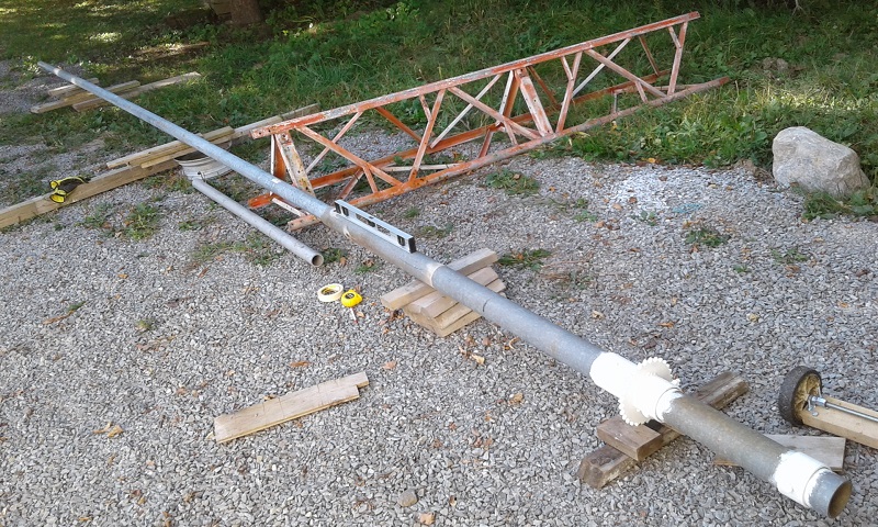
I improvised a jig to do the machining. Before cutting the total assembly is quite long at almost 30'. Setup was difficult due to the 170' weight of the new pipe! The lower mast is on the right, complete with cog for the chain drive and sleeve to sit on the lower bearing. The ungalvanized steel parts and cuts were cleaned and painted (or repainted) to protect against rusting.
It took awhile to get both pipes parallel and the smaller pipe centred in the larger one. I used a level on top and a straight edge on the sides to achieve this. Shims were used to centre the mast on the inside. I then only had to mark the spots for drilling the mast through the existing holes on the lower mast. I had liberally applied masking tape to the mast so that I had a good surface to mark up. (Note: the LR20 tower section is a recent acquisition that I used as part of the jig. Why I have it will be covered in a future article.)
All I had to do was slide the pipes apart and drill. Putting 17/32" holes through 0.25" of cylindrical steel is not easy to do on the ground with a hand drill! There was no convenient way to use a drill press. Plenty of drilling lube kept the bit and work from burning up. Splice hardware is ½" grade 5. The holes are slightly wider than ½" to ease insertion of the bolts through the two pipes.
Finally, after weighing the options, I chose to cut the mast so that 10' (3 meters) was exposed above the top plate. Why I chose this height is discussed below.
Adapting antenna to a 3" mast
Antennas going to the top mast required some modification. The boom-to-mast clamps on most commercial antennas will not fit a 3" mast. In my case that meant some metal work on the Cushcraft XM240 40 meter yagi and Hy-Gain TH6 tri-band yagi. The XM240 was taken off the Trylon in the spring in preparation for moving to the new tower. The TH6 was last used by me over 25 years ago. Both were refurbished for this project in addition to adapting them to the 3" mast.

Four holes for the saddle clamps were drilled through the plate. I wanted to reuse two of the holes but could not because that would place the new holes too close to the existing ones and therefore weaken the plate. I was careful to ensure the boom splice bolts would not interfere with the new clamps.
The mast will now be ~1" off centre. It's still well enough balanced that I did not bother with a counterweight on one side of the boom.
The truss plate was entirely replaced by a Cycle 24 muffler style clamp. Since they proved to be more robust than expected I chose to mount the guy turnbuckles eyes directly onto the ends of the u-bolt rather than machining a plate to fit onto the u-bolt. In the spring we'll see how that works out.
I modified the (provided by the previous owner) custom boom-to-mast clamp on the Cushcraft XM240 40 meter yagi to include an integrated truss support. This is necessary since the truss will extend above the mast. The reasoning is explained in the following section.
After fitting the DX Engineering 3" saddle clamps there was enough room on the side to attach a heavy gauge length of aluminum angle. I used what was available, but a pipe is a better (stronger) choice. Since the truss support is now off centre a small amount the length of the truss cables must be adjusted to fit.
The truss is tensioned on the ground rather than on the mast. The turnbuckles are unreachable when raised to its final position. This is a common technique I've seen at several large contest stations. I liked it so I borrowed it. The mast really needs to be at least 13' (4 meters) to support a boom truss for the top yagi. However this would add additional weight that is not needed, make the mast too long for my gin pole when lifted above the pipe's centre of gravity and climbing that tall a mast to install and service the yagi is unwelcome.
The tram line to raise the antenna actually runs between the boom and truss. Indeed, as I write this the XM240 has already been trammed onto the tower this way. But that's for another article.
Bearing plate
The tower came with a blank plate that is similar to the bearing plates that support the lower mast. I used power tools to grind off unwanted bits and accumulated rust. Once the upper mast was selected I ordered a similar industrial deep-groove bearing to act as a thrust bearing at the top of the tower. The lower mast bearings are NSK while this one is by FAG. All are sealed bearings, as are the bearings in the prop pitch chain drive unit. Weather covers are not mandatory but since they can be helpful I may add those later.
Deep groove bearings of this class are quite good for amateur applications. They have excellent specs for both axial and radial loads, which is unlike too many of the mast bearing marketed to hams. However they are not adjustable. The size of bearing must be carefully selected to fit the mast. This is not difficult since it happens that metric bearing sizes have just the right dimensions to suit common pipe sizes (IPS) used in Canada and the US:
- 1.5" nominal (1.9"/48.3 mm OD): 50 mm bore / 0.85 mm gap
- 2.5" nominal (2.875"/73.0 mm OD): 75 mm bore / 1.0 mm gap
- 3" nominal (3.5"/88.9 mm OD): 90 mm bore / 0.55 mm gap

A template for placing the bearing was made in much the same way as I did previously. First I confirmed that the plate fit the tower girt, found the centre and finally overlaid a trace of the bearing and the mounting hardware, all of which are shown above left. When all was aligned I drilled ½" holes through the ¼" steel plate and test fitted the bearing. It was then removed to paint the plate; the other bearing plates are galvanized, but not this one.
The bearing plate was slipped over the upper mast on the ground and lifted as a unit. The clamp keeping it there was the same one used to assist with the mating of the two masts. I had one oversight, forgetting that the bearing plate and the gin pole could not both be in the same place at the same time!
 |
| Oops! |
Raising, mating and alignment
A friend and his SUV once again provided the muscle to lift the masts. Their respective weights are approximately 75 lb and 100 lb, plus the bearing plates. The lower mast had to first be lowered into the tower so the upper bearing for the lower mast could be affixed, after which the lower mast was pulled up through the bearing and the lower plate attached. The upper mast was awkward due to its ~14' length, which even a tag line couldn't prevent from persistently catching on the top guys. This was easily resolved when I climbed the tower.

On the left you can see the clamp that stop the upper mast in the correct vertical position to drive home the bolts. The lower mast is rotated to get them aligned, assisted with tape markers on both pipes. With the clamp removed you can see that cross bolting the pipes is inadequate for keeping them concentric. The gap all around is ~3/32" (0.095").
This can only be resolved by filling the gap. When I couldn't easily locate 3/32" steel stock locally I noticed that the galvanized perforated strips I had in stock (and are found in hardware store everywhere) is 0.74" thick. That's a pretty good fit. All I had to do was cut several lengths, carefully curve them in my workshop and hook the end so they can't slide through.
On the tower I had little trouble pressing them down into the gap with the encouragement of a large wrench. Two of the shims are quite long, reaching down to the lower bolt to eliminate play at the bottom end of the upper mast. Once done and the upper bearing position tweaked the 200 lb of match spun easily in my hands. I already had the chain engaged, so the rotation included the prop pitch drive unit. The motor was added later since with it mounted the mast could only turn by powering the motor.
You may have also noticed that I replaced the splice bolts. The original 4" bolts were barely adequate to accommodate a nut and lock washer, and lock washers are not ideal for curved surfaces. The replacement bolts are 1" longer. The lock washer was replaced with a flat washer and locking is achieved with two nuts.
With that the mast was ready for the antennas to be raised.
Notes on mast strength
There seem to be two types of ham when it comes to selecting a mast: those who use whatever is at hand and those who must have the very best. A minority engineer the mast strength to the application. As to how strong a mast needs to be, well, it should as strong as it needs to be and no stronger. Not strong enough and disaster is awaiting its opportunity. Too strong adds unnecessary cost and difficulty.
I use a spreadsheet based on the ARRL mast strength calculator. The mast itself is nothing special, simply A53B grade. With my planned loads it is strong enough to survive 150 kph winds with the antennas I am mounting this winter. Next year there will be changes yet to be determined. In all likelihood I will end up with a better rating when a bigger yagi is mounted just above the top plate and a smaller yagi up top. I also have the option of substituting a larger mast.
Within reason I am not concerned about the load on the tower itself, which I know is perfectly up to the task of supporting a 3-element full size 40 meter yagi low on the mast. There is little bending moment for even a big antenna mounted close to the bearing plate, so a large diameter mast is to assure twisting strength (wind torque) and prevent slippage in the boom-to-mast clamps.
If the mast strength is not up the task -- wind load for your locale -- you have a few options:
- Higher strength material: Although difficult or expensive to source a higher strength steel may be the best option. The yield strength of A53B class steel, the lowest and least expensive structural grade, can be doubled or tripled if you are willing to go that route.
- Greater diameter: Increasing the pipe diameter is the superior choice in comparison to increased wall strength. Play with bending stress calculators and you'll soon discover this truth. Standard structural pipes of greater diameter are readily available almost everywhere, and are often galvanized for the pipe sizes hams would choose for masts.
- Butting: This is a material technique to increase wall thickness where the bending moment is greatest. Butted steel tubing has been used for high-performance bicycle frames for a very long time. The special tooling makes these tubes very expensive. You can often nest the next smaller IPS pipe in a Schedule 40 pipe. For example a 2" IPS pipe (2.375" OD) slides inside a 2.5" pipe (2.875" OD; 2.469" ID) with a small gap. Dave Leeson W6NL discusses using aluminum pipes this way for antenna booms in this book Physical Design of Yagis Antennas. Since the increase in bending moment is linear the butt pipe or tube only needs to be long enough to the position on the mast where the bending moment is survivable. Unfortunately, my 2.5" pipe has 0.25" walls and I cannot slide a 2.375" OD pipe inside it. This is where you discover one difference between pipes and tubes: pipes have a seam, and that seam is not ground down on the inner surface. You can see an example of this in the earlier picture of the mated masts.
- Antenna change: The last resort is to go with smaller antennas or lower them on the mast until the wind and ice survival objective is met. Many hams are loathe to do this even when the on-air performance difference is small.
A lesson
Many years ago I help to remove a tower and antenna system where the tower twisted in the wind and broke. Only the over-strength mast held it and the antennas together, preventing a ton of steel and aluminum from striking the close-packed suburban houses below! Removal required a very large crane and running interference with the extremely unhappy municipal authorities. My job was to climb the broken tower and rig the attachment between the tower and the business end of a 125' boom on a 25 tone crane.
Trust me, you never want to be in this situation. Out in a hay field a tower or mast failure may be only an expensive lesson. For most hams who live in urban and suburban settings it can be a disaster far beyond your capacity to deal with and get over.
No comments:
Post a Comment
All comments are moderated, and should appear within one day of submission.