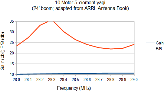
The project for a 5-over-5 stack on 10 meters is progressing well. The yagis are built, tested and adjusted, and are slated for raising in October. Although they are smaller than their 5-element 20 and 15 meter cousins that I built two years ago, the performance is similar and the construction techniques and challenges are identical.
To make best use of aluminum on hand I changed the original element design to use ¾" tubes for the centre sections. The final taper schedule for each half element:
- ¾" × ⅛" : 30"
- ⅝" × 0.058" : 33" (+ 3" overlap)
- ½" × 0.065" : variable length tips
The taper schedule was modeled in EZNEC to adjust the tip lengths to resonate the elements (X = 0) at the same frequencies. Scaling is necessary to preserve performance and frequency range when you deviate from the design. For the SDC (stepped diameter correction) I calculated the effective diameter of the element-to-boom clamps using the W6NL equation. For a ¾" tube on a 4" × ¼" plate, the effective diameter is 2.4". The clamp length for each half-element is 2".
I had a challenge ordering suitable clamps for the element-to-boom clamps. Importing of the ideal fasteners from elsewhere is either prohibitively expensive or the dealers refuse to export. Canadian dealers are not as willing as they have been in the past to do special orders. Other options involved calling in favours to use non-retail suppliers, and I didn't want to do that. I resorted to online sites like eBay to find what I wanted. Once I had the parts I drilled the plates to match the hardware.
To further economize I made the booms out of pipe in my stock. The weight is higher than needed for these yagis but since it's 10 meters the overall weight increase is small. The pipes are 1-½" schedule 40 or 80 (1.9" OD), joined by sections of 2" schedule 80 pipe (2.375" OD, 1.939" ID). The fully assembled yagis weight 43 lb and 52 lb. The lighter one will be the upper yagi of the stack, that will be mounted at the top of the mast on the 150' tower above the planned 3-element 40 meter yagi.
The SWR bandwidth of the yagi is around 900 kHz. That is good enough for DXing and contests. If you operate above 29 MHz (e.g. FM) the antenna should be scaled accordingly. However, you will lose performance at the bottom of the band.
I adjusted the design optimize to my requirements and make the best use the available bandwidth. One change was to shift the antenna up by 100 kHz to get closer to 1 MHz SWR bandwidth with negligible impact on gain and F/B performance.
The model uses a beta match (hairpin) for ease of modelling and for compatibility with SDC (stepped diameter correction). The gamma match I use is functionally the same, and so are a variety of similar "transmission line" matching networks. We'll see the proof shortly.
Construction of the element was no different than that of the 20 and 15 meter yagis so I'll point you there rather than repeat myself. Since there are two of these 5-element yagis, there were 10 elements (20 half elements) to be built. That entailed a lot of cutting, drilling, reaming and filing. I started in August and finished in mid-September. It was a lot of work.
The element-to-boom clamp plates are shorter at 4" × 4" × ¼" but otherwise the same. Due to poor planning, D2 (director 2) on one of the yagis was on a 2.375" pipe. Since the plates were already drilled, I experimented in software with D2 shifted several inches so that it would sit on a 1.9" pipe. By adjusting its length a small amount the performance was close but not the same. Since the designs are already greatly optimized any alteration has an effect. I decided to leave D1 where it was and made a new plate to fit the larger saddle clamps.
I was careful to adjust and measure the half element lengths to be within ⅛" of the modelled lengths. As the frequency increases the need for accuracy also increases. There is little sense investing a large effort to design and build a high performance yagi to then get sloppy and lose some of that performance.
The antenna is large but smaller than many of my earlier projects. It was still a challenge moving them from the driveway, where they were assembled, to the the hay field where they were to be tested and then lifted onto the tower. A friend and I had to carry the heavier one the long way around because of the difficulty of navigating trees and other obstacles. Although the antenna isn't terribly heavy it is no easy job to carry it a few hundred meters by myself, as I did for the lighter of the two.
The rigging to tune and adjust the 10 meter yagis is similar to what was done for 3 of the 15 and 20 meter yagis, except that the antenna size and required height are lower. This is the same rigging used to lower and lift the TH6 recently, which is no accident: I planned it that way to minimize the work. After raising the height of the tram line and lift pulley, the same rigging will be used to tram the side mount 10 meter yagi to 110' (actually about 33 m).
The short length of coax looks silly with the antenna analyzer hanging off it in midair. It was an expedient choice since I didn't have a ready made length of coax that would do the job. What I did have was the recently assembled delay line for the lower 20 meter yagi -- 6.9' of RG213 -- so that's what I used. I'll install the delay line when tuning the 10 meter yagis is compleete.
Despite the short bit of coax and with the help of a step ladder it was possible to adjust the gamma match and measure the impedance with the antenna as high as 15' (4.6 m or 0.43λ) which is high enough to put it in virtual free space.
The shorter gamma rod separation helped to place the coax connector at the same level. For the greater separation on the 15 and 20 meter yagis the connector was higher (closer to the boom) with a vertical wire down to the capacitor. With careful calculation and construction it is a very good fit. I prefer this approach since it improves mechanical robustness.
For initial tuning I used a temporary strap and the gamma rod and capacitor are longer than required. I have learned to distrust gamma match design software. To my surprise the calculated dimensions turned out to be quite accurate, to within 1" (3 cm) and 3 pf (4 cm of RG213 inside a ½" gamma rod) for centre-to-centre spacing of 3" from the ¾" element centre tube.
Further playing with the software suggested, if reliable, that the antenna impedance at 28.5 MHz is 30-j35 Ω versus the 30-j30 Ω predicted by EZNEC. Design and measurements are done at 28.5 MHz since that is where the SWR is predicted to be minimum (1:1), and the SWR over the band should be as designed.
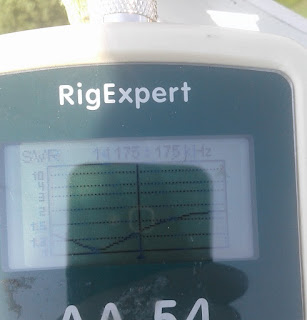
Compare the measured SWR from 28 to 29 MHz at 12' height to the free space SWR predicted by EZNEC above. They are almost indistinguishable. Modern software tools are truly awesome. There is a glitch right at 28.0 MHz that isn't there in other trials. I think the coax connector to the analyzer wasn't tight enough at the time. When the antenna was raised 3' higher to 15' the gamma match required a slight tweak.
The gamma match was subsequently altered to make the components smaller. I did this by shortening the each half of the driven element by ½" to increase the capacitive reactance. This allowed shortening the gamma capacitor, which is desirable for mechanical robustness. The capacitor length was trimmed so that the rod could be shortened while leaving room for further adjustment if needed. After adjustment the SWR curve was almost exactly the same. Perfection is not the objective since. For the side mount yagi, there are almost certain to be guy interactions that will alter the impedance and pattern a small amount
With the antennas built and tuned the remaining parts were the boom-to-mast clamps and boom trusses. In my junk box I found a ¼" aluminum plate with holes in exactly the positions needed for the lower, side mount yagi which uses a short length of 1.9" pipe for the mast.
For the upper, rotatable yagi I chose a ⅜" aluminum plate from my junk box. As for the upper 15 meter yagi, there is an integrated boom truss support. This allows it to be placed at the very top of the mast, as far as possible above the planned 40 meter yagi.
At the time the picture was taken the fittings for the clamp are incomplete. There were a few more holes to be drilled and saddle clamps selected. One of the 3" DXE clamps for the 2.875" mast is shown, while a second had to be rescued from a "temporary" use on one of the towers where it's been for 3 years.
Still to be done are the coax chokes and boom trusses. For the latter, I am using what I can find in the junk box. The current plan is for short lengths of plated chain anchored on the boom with old muffler clamps, ⅛" aircraft cable as the truss cable and galvanized turnbuckles connected to the mast. It won't be pretty but it will work and nothing has to be purchased.
Coming up is the raising of the yagis and construction of the stack switch and phasing harness. That will have to wait until the antennas at the top of the tower are removed -- TH7 and 40 meter dipole -- and the tower is rigged to lift the as-yet incomplete 40 meter 3-element yagi. Other project have intervened so it will be two weeks or more until both 10 meter yagis are raise.


