I purchased my TH6 and Ham-M rotator from a local ham back in 1985. At that time it had been on his tower for at least 10 years. In those early days the hardware wasn't stainless steel so much of that had to be cut off and replaced. The dreadful BN86 balun that comes with the antenna was soon discarded in favour of a coax choke. A couple of the traps needed service and I puzzled out their disassembly and repair -- I couldn't benefit from an internet search back then.
When done it performed flawlessly until 1992 when I dismantled the tower and antennas and exited amateur radio for over 20 years. I kept the antenna, and indeed I sold very little of my equipment in the intervening years. I restarted in the hobby in 2013 in a small way, gradually increasing the size of the antenna systems. The driven element was put to use as a trap dipole for a short time.
 In 2017 the antenna was refurbished and raised to the top of my new 150' tower. A couple of mechanically suspect traps were given cursory attention since it was the onset of winter and time was of the essence. Trouble reared its head the next winter. I had planned to have it up there for no more than 6 or 8 months but changed plans meant leaving it up there another year. Hope is a poor strategy for ensuring antenna reliability.
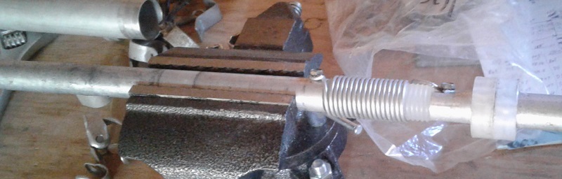
Again I failed to repair the suspect traps when I had it on the ground this fall. It went intermittent during CQ WW SSB this past weekend. This time I would have to take action. It was a simple matter to isolate the problem. With an antenna analyzer attached I wiggled the elements within reach of the tower. The SWR bounced around when one half of the driven element was shaken. The trap itself wiggled which made the failure point obvious. It was a simple matter to pull the half element out and lower it to the ground.
Trap structure
Hy-Gain yagi traps are not designed to be opened and serviced. Of course countless hams, myself included, do it all the time. The first time a trap is opened it is difficult to separate the parts without causing damage if you are unfamiliar with how they're built. A mistake usually makes it unusable. It is worthwhile to learn how to do it properly if you insist on doing repairs yourself.
The first thing to know is what's inside: the components and how they're put together. All the Hy-Gain traps for the tri-band yagis are the same no matter the model, be it an ancient TH6, a relatively recent TH11, a TH3, an Explorer 14 and so on. Indeed there are only 4 traps for the tri-band yagis:
- 10 meters: there is a different version for parasitic elements on some yagis
- 15 meters, for directors and reflectors
- 15 meters, for the driven element
Compare body lengths and peek in the weep holes and you have all the data you need to identify the trap. That said, I haven't directly compared the two versions of the 10 meter trap. Hy-Gain sells new traps at a reasonable price, and even most of the component parts. That's an alternative to repair. Go to their web site and search for "trap".
I pulled a broken 10 meter trap from my antenna junk box that I scavenged from another ham's antenna nightmare. The coil form and tab connecting the shell (capacitor) to the right tube are broken. I don't know the story of how it broke. Laying out the pieces as I've done gives an idea of what's inside. These traps are really very simple devices and quite robust when not abused in service, disassembly or reassembly.
The three sheet metal screw that secure the coil end and the shell tab are frequently criticized. While not a superb choice the screws are tough and have an integrated lock washer, and when the traps are properly assembled the screws are under very little stress. I judge the design a reasonable compromise between cost and robustness. The trouble comes when the traps are reassembled after service.
The plastic spacers are critical to the strength of the trap. Install them incorrectly and fatigue failures will occur. Their purpose is to keep the inner tube and coil rigid with respect to the outer tube. Since the weakest component is the coil (wire and form) these must not flex under wind and ice loads. When the spacers are properly positioned flex is minimized. It takes two spacers on either side of the coil to prevent the inner tube from flexing.
The inner end of the 10 meter traps (on the right, with the tab) flex the most since the spacers are close together. Over the years the tab can fatigue and break. This is usually only a problem on the driven element since the larger and heavier 15 meter trap on the outer end of the element increases stress on the 10 meter trap.
The spacers are positioned correctly when manufactured. Dimples (small depressions) in the shell hold the spacers in place. There are cavities in the spacers that align with the weep holes so that the spacers don't dam water flow.
To disassemble the trap remove the screw on the shell tab and push the inner tube left with respect to shell as oriented in the picture above. Some force may be needed to push the two left spacers over the dimples. Unfortunately the spacers may suffer some damage but there's no good alternative to getting them out. The spacers on the right will most likely stay where they are during disassembly and reassembly.
To reassemble the trap you push the inner assembly in from the left of the shell. If the rightmost spacers moved reposition them first. The one on the outside comes close to the tab. The other should be pushed from the left to its approximate position. Use the dimples as a guide but don't obsess over getting it perfectly aligned. But do try to have a weep hole aligned with the outer tube weep holes.
Even it isn't in far enough the trap coil screw push it further when it is inserted. Avoid this if possible since is a small risk of damage to the spacer and coil. If the spacer is too far outboard use a blunt metal rod to lightly tap it toward the coil through the outermost spacers weep holes, going around from hole to hole so that it doesn't jam. The most common reason for the spacer to be too far outboard is pushing the inner assembly too far to the right. Move slowly and watch for the tab screw hole to appear. Screw the tab to the inner tube.
Push a spacer in from the left until it is at or near its dimple on the left side of the coil. Hold the outer tube in a non-marring vice while for best control and least risk of damage to the tab. A 1" PVC pipe can be used to slide over the inner tube and apply even pressure to the spacer. Don't push it in too fare (right up against the coil) or you'll have start over again.
Finally insert the leftmost spacer and you're done. Hold each end of the inner assembly check for flex. There should be little to none. Remember to slip on the trap covers. I wrap the covers with Scotch 33+ for extended UV protection. Replacements are cheap if you need them.
Repair
For my repair job I disassembled the 10 meter and 15 meter traps. Although only the 10 meter trap was flexing I chose to do both since I had them in hand.
No wire breaks or loose hardware were evident. This can be a problem when the traps are mechanically unstable because the coil wires or forms will flex and eventually break. There was no damage of this kind just some debris and corrosion. An old insect nest was removed.
I undid the screws at either end of the coils and lightly sanded the aluminum surfaces to ensure good electrical contact. The inner end of the 10 meter trap tube was slightly distorted by the flexing so I pulled it from the coil form and gently applied pressure to the tube with a vice to reduce the freedom of motion it had developed. Perhaps a needless repair but I prefer that the form fit snugly.
As expected the spacers were out of position and that is what caused the flexing. The spacers were correctly positioned (as described above) during reassembly. The half element was then put back together and the dimensions checked. The entire job took less than 2 hours despite proceeding carefully. I wish that I'd taken the same care the last time I did this job!
Back in the air
For late October the weather was warm so I rushed to put the driven element back together before the weather turned. The high wind that day didn't dissuade me since the half element is easy to lift. I stuffed it and the insulator back into the boom clamp and attached the clamp and wires going to the balun and hairpin (beta match shorted transmission line stub). Within minutes I was ready to test my repair.
The element no longer wobbled when shaken. I connected the antenna analyzer to the balun and the SWR was what it ought to be. So far so good. To my dismay the SWR again misbehaved when I wiggled the driven element in exactly the same fashion as before the repair. That was not good. Although the poorly assembled trap need fixing the problem was evidently elsewhere.
Oops!
 Further troubleshooting showed there were two problems not one. The first was found by wiggling every wire and connection on the balun, driven element and hairpin stub. The wire from the stub to the clamp on the suspect half element was intermittent.
It seems that after 45 or 50 years the stranded wire had few intact strands remaining. Nothing lasts forever. I now realize that this was the same intermittent problem that developed earlier when the antenna was on top of the 150' tower.
Hy-Gain yagis of that vintage did not use stainless hardware. The screws and nuts are pretty well welded onto the aluminum tubes of the stubs. Since I was not prepared to tram the antenna to the ground to destructively remove the hardware I used a hose clamp to attach the new wire to the tube.
The wire quality is not the best but it should hold through the winter. I put a few layers of tape on the wire insulation where it might touch the boom clamp for added protection from high voltage and stray capacitance.
Finally the antenna survived the wiggle test. The SWR tests perfectly on all three bands.
The next problem was further down the tower. Where the short length of RG213 from the antenna to connects to the long length of Heliax the UHF to N adaptor was visibly bent underneath the layer of weatherproofing. Although the SWR was fine in the shack this could not be left as is due to risk of imminent failure.
 The Heliax terminated with a male N and the RG213 had a male UHF. Adaptors with an N female on one end and a UHF female on the other end are rare. The 10 meter length of RG213 I grabbed from my junk box had a heavily taped N female on it that looked perfect for what I needed to hook up the newly side mounted TH6.
When I cut away the layers of plastic and rubber I discovered the problem. This old bit of coax was older than I realized. Inside was an adapter I home brewed back in the 80s for LDF4 runs, all with N male terminations.
Oh, to be young and foolish again! Unwrapping this contraption brought back memories. The shells of the N female and PL259 reducer were merely pressed together. It had no mechanical strength at all. I'm surprised it lasted as long as it did. Only the tape holding the halves together allowed for electrical continuity.
The abomination was replaced with an N female barrel connector and a more common N male to UHF female adapter. I have both in abundance since I routinely connect Heliax main runs to RG213 and LMR400 terminations. I taped up the joints and this time I really did had the problem resolved.
Rush jobs coming up
The weather is finally turning colder, windier and wetter. Time to finish the many antenna jobs I have ongoing is running out. Just this week I found time to (finally!) complete my 80 meter vertical yagi. An article on that should be out next week. The 20 meter and 15 meter stacks are slowly progressing, with two yagis tested and working. I am rebuilding the boom of the upper 20 meter yagi so that it is stronger and lighter. Permanent gamma matches to replace the testing/tuning gamma matches are under construction. Other hardware to side mount and mast mount the yagis has recently arrived or will be fabricated shortly.
The time taken to repair the TH6 delays every other job making this problem very unwelcome. The antenna was really proving its worth during CQ WW SSB before it quit working. As the number of towers and antennas grows the probability of a problem arising increases. Problems come in all types. For example, this week I discovered a small pit dug into the bundle of Heliax and other cables running from the 150' tower. Some animal, probably a skunk, dug up a wasp nest that was down there. I inspected the cables -- thankfully there was no damage -- and refilled the hole.
Maintenance is never ending in a growing antenna farm. I am spending some time on the air, entering contests and working DXpeditions. I count myself fortunate to have the time to do all of this and for the friends willing to help even when the weather is unpleasant. They seem to enjoy being a part of this journey.
However it is better to do things right the first time and avoid unwanted repair jobs.
Is the aluminum tube solid tube under the wire wound trap. It appears to be bent in the picture
ReplyDelete73, AD6GE
The coil form is plastic. The tubes attach over the form ends. The form is solid and the aluminum tubes are tubes, not rods/solid.
Delete73 Ron VE3VN
Were you able to find replacement trap caps (the black end covers) or did you make or repair the originals?
ReplyDeleteHo did you repair or replace the black plastic trap caps?
ReplyDeleteI purchased replacements from Hy-Gain/MFJ and I repaired some by wrapping them in Scotch 33 tape. The replacements from MFJ are inexpensive however I've heard credible reports that they are prone to cracking and UV damage. I haven't had them up long enough to know whether the reports are true.
Delete73 Ron VE3VN
Hi Ron! Enjoy your articles very much. I have a TH-11 that has a vey high swr on 15M >4-5 but is ok on other bands. Does this sound like the 15M trap on the 17M director might be the problem? Thanks,Jeff VE3CID
ReplyDeleteHi Jeff. I had to crack open the TH11 manual in my files to check. You may be correct with your guess. There is just that one set of traps for 15m. It could be anything, even insets nesting inside (don't even ask!). However, also look for corrosion on tube clamps, dry tube joints that have inadequate electrical continuity, broken tips on elements, and the phasing harness among the driven elements. Sometimes the problem is something you would never expect.
ReplyDelete73 Ron VE3VN
Hi Ron. SWR also around 2-3:1 on 17 so I thought a bad trap could affect 17m as well. Resonance point on 15m is actually around 20.250 Mhz which is well below 15M band.I just dread the thought of having to take down this monster antenna.Thanks for advice.73,Jeff VE3CID
DeleteThe resonance frequency of Hy Gain traps are always well below the middle of the band. It is done to make the voltage across the trap smaller that it would be the case if your work frequency equals the parallel resonance frequency of the trap. This mismatch is compensated by the proper size of tubing next to the trap.
Delete73 de SP5EAQ (Eng. electronics)
Hi Ron,
ReplyDeletePicked up an old TH6-DX this weekend for free. It's going to be a project. Most of it is in pieces and this will likely be a winter project. I was looking at all the rusted bolts and nuts and was thinking that while I have everything down and on the bench, it might be a good idea to replace all of it with new (SS?) hardware. What are your thought on this? Leave the old rusted hardware as long as it poses not structural problem (not now anyway), or replace it? I sounds easy to say replace, but all of the bolts will likely have to be destructively removed.
73 Tom KC1ELF
Tom, depends how easy it is to lower and raise the antenna. I usually leave the old rusty hardware until I want to adjust something. The TH6 may be tuned for SSB or CW and you may want the opposite. Some of the old hardware is not easy to remove since the steel is soft and will distort when forced.
ReplyDeleteI use bolt cutter where they fit and I've slipped hacksaw blades between the halves of the element-to-boom clamps. The latter can damage the aluminum until at least one bolt is free. Electrical connections can fail due to the rust penetration so are important to look at (hairpin, driven element). Check the rusty clamps and turnbuckles on the boom truss. For an old yagi like this you may want to peer inside the weep holes of the traps to determine if they need cleaning due to insects etc.
Good luck!
Hello, I just found this nice place on the internet. I bought a brand new Hy-Gain TH-3MK4 antenna from authorized seller. Four days ago, I assembled it and placed on the roof.
ReplyDeleteThe antenna was assembled and adjusted exactly according to the instruction manual and by experienced radio amateurs who have already assembled such antennas.
After installing it on the roof, the antenna does not work well. I did not adjust the antenna to CW, SSB, but to the MID area according to the user manual.
Antenna is in free space at a height of 15m from the ground. VSWR as follows:
14.000 = 6:1, 14.200 = 2:1, 14.350 = 1,25:1.
21.000 = 1,5:1, 21.200 = 2:1, 21.300 = 4:1, 21.450 = 7:1
28.000 =4:1, 28:200 = 3:1, 28.600 = 2:1, 29.000 = 1:1
Over the weekend I experienced the following:
Saturday was windy, the antenna and the elements shook and twisted and I had frequent breaks in reception (the signals varied from S9+20 to S1 and transmission (extremly high VSWR). In one period , I measured the VSWR on all three bands and the results were exactly as they should be after adjusting the antenna to the MID area!
After an or two hour I measured the VSWR again and the results were again not good.
I asked many radio amateurs who have been using these antennas for years, and they all told me that the only possible problem is faulty traps.
So please help me because I dont belive that brand new antenna have problems in their traps.
73 de 9A2M, Hrvoje
Hrvoje, there are too many unknowns for me to know what is wrong, and I do not have the antenna in front of me. Perhaps the following notes will help you to diagnose and correct the problem.
ReplyDelete1. Environment: How high is the antenna and how close to the roof? Is the roof steel/metal? What other conductors or buildings are near the antenna? You ought to be at least 5 meters (1/4 wave on 20m band) above a metal roof for the SWR and pattern to stabilize.
2. Your own description says that you have an intermittent connection. It could be the antenna, but it could also be the coax or a coax connector. Check every fastener on the antenna, including those hidden by the plastic trap covers. Quality control has declined since MFJ bought Hy-Gain. Did you use conductive grease on all tube joints and all the fasteners? That is recommended.
3. Are you using the Hy-Gain balun (e.g. BN86) or other type of balun? It could be faulty or improperly installed.
Good luck!
73 Ron VE3VN
Hello Ron,
ReplyDeleteThank you very much for your quick reply. I wasn't sure if this topic is still active because no one had written anything in it for a long time. It would be great if I could attach some pictures of the antenna here because "a picture is worth a thousand words".
I will try to answer in the order you asked me:
1 The antenna is on a 2 inch O.D. mast, mounted on a rotator. The mast is above the roof at a height of 4 meters. The total antenna is at a height of 14 meters from the ground. The roof is made of ordinary clay tiles. It's not metal. The antenna is in my yard, it's in a free space and I don't have any obstacles or conductors nearby. Take-off is 360 degrees clear.
2. Coax cable and connectors are new, well soldered and instrument tested. The connection to the beta match is also solid, isolated and also instrument tested. Nothing is disconnected or in short circuit . This part is interesting: the screw located on the outside on each of the 12 traps was impossible to tighten! The holes were drilled too wide and the screw was spinning in place. I solved this by drilling a narrower hole right next to the factory drilled hole and only then could the screws be tightened. I did not understand this question: "Did you use conductive grease on all tube joints and all the fasteners? That is recommended."
3. I did not use any balun or RF-Choke.
The antenna has 6 traps for 15m, 2 of which are for installation on the radiating element. I was also careful not to place them elsewhere on the antenna. Although it is not written in the manual, some of my friends which also have similar antennas told me to make sure that each trap is facing the same direction (looking to the antenna bum). I made as they told me.
P.S. My friend recorded raising the antenna on the roof with a drone. He is a radio amateur, but he also deals with video and photo production. He edited the complete montage into a short 3-minute video. If you want, and since I can't post pictures here, I would like to ask you to spare 3 minutes of your time and watch that short video on his You Tube channel:
https://youtu.be/To_7NMozN4o
73 de 9A2M, Hrvoje
Hrvoje, we should communicate by direct email. My email address is my call sign at myrac.ca
DeleteI will watch the video later because I am very busy today. Hopefully that will help me to understand better.
73 Ron VE3VN
Hi Ron! Just a follow up on my TH-11 high swr problem. Turns out pigtail leads on phasing tubes were broken on 17M & corroded badly on 15M. Replaced these & problem solved. This was one of your many suggestions so thanks & 73. Jeff VE3CID
ReplyDeleteHi Ron,
ReplyDeleteJust want to let you know that I solved the problem with my Hy-Gain TH-3MK4. I returned it to the seller and got a full money refund.
73, 9A2M, Hrvoje
Hrvoje, sorry that it came to that. The quality issues from MFJ manufacture have become a problem. Not sure what will happen to Hy-Gain antennas and parts now with MFJ shutting down. It is perhaps appropriate to replace it with a better product.
Delete73 Ron VE3VN
Hey Ron, enjoyed reading your article on hy-gain's antenna refurbish. i have a hy-gain TH3jrs, nothing fancy. however, the person i got it from said it didnt work. it has been sitting in the shed for about 5 to 6 years now and decided to take it out and give it a go. yeah, the SWR is off and began to wonder if he had assembled the antenna correctly. Since there are no markings on the traps i decided to open them up. good thing i did because they are filthy inside. anyway, is there a way to identify the traps based on number of turns. this is what i have, "inside" is the trap closest to the boom, "outside" is the trap on the far end:
ReplyDeleteREFLECTOR inside 25 T
REFLECTOR outside 45 T
DRIVEN EL inside 22 T
DRIVEN EL outside 38 T
DIRECTOR inside 26 T
DIRECTOR outside 45 T
any help will be ingratiated. :-)
Joe
WA2L
Atlanta
Joe, I can't comment on your turn counts other than there appear to be errors. All the inside traps are for 10 meters and they should be identical. The outer traps are all for 15 meters, but the ones for the driven element are made from copper wire rather than aluminum. That is, there are 3 models of traps in a TH3. Note that late model Hy-Gain trap yagis made by MFJ have often shipped with aluminum 15m traps on the driven element, which is a problem. But yours sounds to be much older.
Delete73 Ron VE3VN
Hi Ron, do you know what the correct turns counts for the traps should be? I am working on an nec model of the th-5. Thanks
ReplyDeleteSorry, I don't know. You can probably count the turns yourself by peering through the weep holes. Keep in mind that the traps are tuned outside the band, not within it. Read this article for details on Hy-Gain and other traps: https://www.w8ji.com/traps.htm. Also, the capacitor value (the tube shell over the coil) is difficult to measure or calculate in Hy-Gain traps. So use W8JI's measurements to help design your traps, if you must.
Delete73 Ron VE3VN
Hi Ron - I have a TH6 DE that I want to use as a trapped dipole for a low bi-directional 2nd triband antenna on my tower. I have a TH6 at the top and it works great. Can you offer any comments regarding the lengths from feedpoint to 10m trap, and the spacing of the 10m and 15m traps? I have the TH6 DE on a 10' mast on the patio deck for tuning, and rather than spend hours back and forth adjusting tubing lengths, I am looking for a better starting point. I know the TH6 has a shorted stub on the DE that cancels out some Xc that is present because of the Hy-Gain insulated element to boom clamp as well as the effects caused by the other elements. TU es 73, Charlie N9CO
ReplyDeleteCharlie, check out this article: https://ve3vn.blogspot.com/2013/07/summer-antenna-th1.html
DeleteThere are a few tidbits from that ancient article about modifying the TH6 DE dimensions. However some playing around with the dimensions is likely still necessary. You can get close without lifted to its full height every iteration. Search my blog for "th1vn" and you'll find a few related articles.
73 Ron VE3VN
Thanks, Ron!
DeleteRon - my TH6 DE was modified to NOT use the Hy-Gain boom to element clamp. Instead, I inserted a fiberglass rod and supported the antenna with 2 insulated clamps on each side using a thick aluminum plate that attaches to a leg of my Rohn 45. The spacing between element halves is about 1.5". I have a choke balun.
DeleteInitial tuning was done on my deck using a 10' piece of steel TV mast. Antennas was about 12' above ground. With the stock TH6 CW dimensions, the VSWR mins were all too high. I lengthened the distance between feedpoint and the 10m traps by 2", lengthened the distance between the traps by 2", and shorted the tips by 2". VSWR mins were reasonable.
After mounting on the tower at 36', 1 foot above the bottom guy brackets, my VSWR readings are not the best. 10m is about 2:1 across the band. 15m is a bit lower, but higher in the band. I now have a great 20m phone antenna - not what I was shooting for!
I really need to borrow a friends VNA and make some real RF measurements. My gut feel is that some form of feedpoint compensation will be needed.
Thanks for the feedback and pointing me in the right direction!
Vy 73,
Charlie N9CO