10 meter yagis are in my 2021 plan. These will be smaller than the long boom yagis I built for 15 and 20 meters last year. On a 24' boom, 5 elements on 10 meters has the same performance as a 5-element 20 meter yagi on a 48' boom, and that is certainly a huge antenna. Despite the relatively small size the performance is excellent.
Many hams in pursuit of ultimate performance take advantage of the smaller size and increase the boom length by 50% or more than 24'. Diminishing returns come into play so one should consider the trade offs. For example, 6 elements on a 36' boom (50% longer) has about 1 db more gain, a narrower beam width and a slightly broader SWR bandwidth. The wind load is substantially greater so the boom, truss and mast must be stronger, and that has a cost.
For the DXer the additional performance may be worthwhile. As a contester I would rather have a broader beam width, perhaps a little less F/B and acquire additional gain with stacking. The objectives are to increase the number of workable stations, punch hard into high population regions (Europe, Japan, US) and rapid direction switching. A stack of 2 or 3 individually rotatable and moderate size yagis is a good fit for my style of operating.
Don't reinvent the wheel
The time when we played with yagi designs to optimize them has passed. Computers and software optimization has replaced the excesses of uncertainty and experimentation, at least for mono-band rotatable yagis for the high bands. Sure, you can try it yourself but in the end you will almost certainly end up with a design that is little different from the many computer optimized designs that are already published. Wire yagis on the low bands are another matter with their broader range of design parameters, but here we're discussing 10 meter rotatable yagis.
What I do is to pick a published design and perhaps tweak it to get a little more gain or a little more bandwidth, depending on my need and the construction material on hand. When I do so there is often a performance metric that will degrade, if only slightly. Optimum designs really are optimum across all metrics. More often I will scale a yagi from one band to another, do the SDC (stepped diameter correction) for my tube taper schedule and element clamps, choose a matching network for the feed point and then build it.
This 10 meter antenna is right out of the ARRL Antenna Book. There are 5 elements on a 24' boom and it performs well from 28.0 to 28.9 MHz. Getting more bandwidth would require more elements and a longer boom, or giving up gain and F/B. There is no free lunch. As I described earlier, this design very nicely suits my particular objectives. That is, it's optimal in general and optimal for me.
Why would we need more bandwidth than 900 kHz? Having 900 kHz on 10 meters seems plenty yet there are times when more can be useful. Although I don't normally operate above 28.8 MHz, when the solar cycle is at maximum and there is a phone contest the activity extends above 29 MHz! Indeed, my first CQ WW SSB world #1 plaque in 2014 in the QRP category was due to an extraordinary run into Europe at a frequency above 29.1 MHz.

Now that I run higher power and my antennas are bigger there is less need to go quite so high in the band to find a frequency for running. I can compete in the more crowded and popular part of the band. That eventuality is a year away as the new solar cycle waxes.
Choosing tubes and calibrating the model
The tubing schedule for my home brew yagis is not what is typical of commercial antennas, due to cost or availability. As I've related in the past, that although Canada is awash in aluminum and aluminum products at reasonable prices, tubes of the alloy and sizes needed for telescoping yagi elements must often be imported at high prices. So I adapt by choosing alternatives and machine tubes as necessary to make them fit.
First I decide on the tubes and pipes to meet the requirements of survivability, cost and the ability to nest easily or with minimal machining. Next I sit in front of the computer and scale the yagi design for my selected element construction. Element taper has a modest though important effect on the reactance and therefore resonance.
For this design my initial selection is 1" schedule 40 6061-T6 pipe 3'-4" long for the element centre. That may change when I compare the spot price this spring. The length is chosen to eliminate waste when cutting a 20' standard length pipe. The OD is 0.84" and the ID is 0.622", for a wall thickness of ~0.09". This is about the same strength and weight as nesting a ⅝" × 0.058" tube inside a ¾" × 0.58" tube, as specified in the ARRL Antenna Book. The pipe is easy to acquire locally. Reaming the pipe to nest a ⅝" tube is a quick job in my workshop with the 0.627" reamer in my toolbox.
The ⅝" tube will be 2' long per half-element. For the usual 3" nesting, the net length is 21". Again, this is to eliminate waste from sectioning the 6' long tubes -- the standard length of aerospace aluminum alloy tubes is 12'. The element tips are ½" × 0.065" tubes. Boom construction will be decided by what material I can acquire surplus at a lower price than new tubes and pipes. Based on other designs I expect that a 2" × ⅛" wall tube or similar size pipe will support the antenna well in extreme weather.
Deviations that do not matter much for a single element antenna like a dipole become quite critical in a high performance yagi. Without taking the taper into consideration the yagi will still work though not nearly as well as it might. A little effort up front ensures that the time and effort you invest will pay dividends once the antenna is on the tower. This is not the place to be lazy or to take shortcuts. Mistakes happen, just as it did with my 15 meter yagis.
One of the easiest ways to calibrate the element with a published design is to model one element and determine its resonant frequency -- where X = 0. Do this in free space and without a boom. This is accurate for a yagi made of tubing and elements clamped to a plate sitting on the boom. The effect of the boom is a small fraction of the boom diameter. A yagi well above ground is effectively in free space, and therefore so are the elements. This is quite different from a one element antenna over real ground which will be affected by the ground.
I modelled the driven element per the ARRL Antenna Book and found a resonant frequency of ~28.85 MHz. Next I rebuilt the element with my selected tube schedule (it may change before it's built). I adjusted the ½" tips so that the resonant frequency was exactly the same. My half-elements are only ⅛" longer. It's chance that they agree so closely.
For such a small difference it is sufficiently accurate to arithmetic scale the half-elements by lengthening them by ⅛". For larger differences it is better to scale the elements geometrically. Do this by calculating the ratio of the original and scaled lengths and multiplying all the half-elements by that ratio. For exceptionally large differences or for elements with unique tapers an SDC must be redone for those elements by following the calibration procedure described above.
Model Performance
This is the boring part. The modelled antenna performs very much like the one in the ARRL Antenna Book. It is nevertheless a useful exercise to confirm that scaling had no deleterious effects and that the model is reliable.

The gain is very flat from 28 to 29 MHz. It rises from 10.1 dbi at the bottom of the band to peak at 10.6 dbi at 28.8 MHz. The slight 0.1 db gain drop at 29.0 MHz is mostly due to ohmic loss in the aluminum elements as the radiation resistance falls to a low value. There is little here to complain about.

Overall performance is excellent for a 10 meter yagi of this size. There was nothing found in this exercise that deters me from proceeding with construction of these antennas.
Feed point match
The 10 meter band is quite wide at 1.7 MHz. Put another way, the range is 6%. In comparison, 40 meters is 4% (7.0 to 7.3 MHz). We've seen before that it can be a challenge to match a 40 meter yagi across the entire band, and 10 meters is wider.
A full band match isn't necessary. For CW, SSB and digital modes it is sufficient to cover 28.0 to 29.0 MHz, or a little more than half the band. This is doable without special techniques such as OWA, with its requirement for an extra element as a coupled resonator the driven element.
The SWR curve for this antenna shown in the ARRL Antenna Book is below 2 in this 1 MHz segment. I can live with that.
I have not decided on a matching network. I could use a gamma match, as I did for my 15 and 20 meter yagis, or I could use a beta (hairpin) match. The latter requires a split element that is isolated from the boom, and that involves additional work. Since the elements are substantially smaller it is less difficult to do this in a robust fashion. I have the fibreglass tubes to support the split elements and the u-bolt interiors for the element clamp can be covered in rubber. The rubber needs UV protection, and that is likely easier to achieve than machining suitable plastic stock.
The SWR bandwidth will be about the same with most conventional matching and feed systems. In the model I used a beta match since it is far easier to implement with NEC2 than a gamma match.
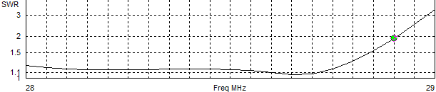
That's pretty good. The SWR remains low for a few hundred kHz below 28.0 and so it is tempting to shift the entire yagi upward. The downside is that the gain and F/B are poor at the lower frequencies. For my purposes it is preferable to maximize gain and directivity in the band segment of interest, and an SWR below 2 at up to 28.9 MHz is acceptable. I expect to rarely venture that high in the band.
Where they're going

The lower 10 meter yagi is more difficult. Although it doesn't need to be too far beneath the upper yagi there are guys in the way. Even if its orientation is fixed the proximity of the upper guy set will have unwanted interactions, mostly of the non-resonant variety. Directivity will be impacted by the growth of the minor rear lobes. The degree of the interaction will have to be determined before the antennas are installed.
If it is to be rotatable then it must go lower to clear the guys. This would separate it from the top yagi by 30' to 50' (0.9λ to 1.5λ).
For 30' spacing the stack elevation pattern is good but not great. Although gain is a near perfect 3 db the nulls in either yagi are not entirely filled. It may be better to separate the yagis closer to the maximum of the range mentioned earlier. Alternatively a third yagi at a lower height would be even better, and supply additional gain.
I am undecided on the placement of the lower yagi. There are other antennas planned for the tower, including a 40 meter yagi. Further investigation is required.
Construction plan
I have no firm construction schedule as yet, other than wanting two of them on the tower by early autumn. In the spring I'll hunt for new and surplus material from my usual suppliers. These antennas will be easier to build than their larger cousins, the 15 and 20 meter 5-element yagis. That removes some of my worry about keeping to my plan for the year.
No comments:
Post a Comment
All comments are moderated, and should appear within one day of submission.