Top band season will soon wrap up for me. While giving a tour of my station to a visiting contester the snow and ice was sufficiently thawed that it was once again possible to trip on the 160 meter antenna radials. That means hay growing season is approaching and soon I'll have to roll up the radials until late summer. Until I come up with a permanent antenna this mode of operation is necessary. It is therefore a good time to reflect on the season that was.
Still no QRO
For my second year with an effective 160 meter antenna my accomplishments are incremental rather than spectacular. Surprisingly my DXCC count went up very little: it now sits at 108, only 11 more than after last season. I'd be substantially higher were I running QRO since the opportunities were there. I continue to make do with 200 watts, and less in contests to stay within the low power category. In the Stew Perry TBDC I operated 5 watts once again to hand out QRP point multipliers.
TBDC brought out lots of activity around the world making it possible to try to do the impossible with QRP. One was a new country: 3V8SF. Since he was running low power we each earned 90 points for the QSO. Perusing the interim results this appears to be the highest point QSO in the contest overall. My other success was surpassing 8000 km distance by working RW7K. It took awhile but he somehow managed to tease my call and grid out of the noise. Kudos to him, and to the horde who stood by to let it happen. My challenge was find novel ways to communicate the information to help him as best I could.
Aside from the successes there was far more DX that I failed to work with low power. Of particular note were the many African DXpeditions: 5V, 5X, 7P, FH, 3B8 and more. The inland operations were especially difficult despite being within reach because they found it a challenge to put out an exceptional. Looking west, island operations such as VP6D (Ducie) and T31EU (Central Kiribati) I worked quite easily since they had great signals by using the Pacific Ocean as a ground plane.
Typically I can hear the DX. The reverse is often not true due to asymmetry of power and noise. To corrupt a common saying: you can't work them if they can't hear you. More DXpeditions than ever are taking amplifiers, helping them to be heard with their modest antennas and giving me a false sense of hope. Tropical QRN even with directional receive antennas on their end are frequently not enough to get my low power signal into their logs.
It is possible to work the world on 160 meters with 100 watts if you are willing to wait for the occasional exceptional opening, but a kilowatt is necessary to routinely work the DX. It is increasingly likely that I will make the jump in time for the 2019-2020 season. However I will continue with low power or QRP in select contests.
Waiting for exceptional conditions
Despite many differences there are commonalities between 6 and 160 meters. Without propagation enhancement it is possible to work out to some distance any day of the week. Enhanced propagation requires patience, and hoping that the DX happens to be there when it happens. This can happen any day on 160 meters, so in that respect it is less frantic than 6 meters when missing an opening can mean waiting until next year.
But when conditions are hot they can be very good indeed, and especially so for those of us running less than a kilowatt. A good example was one weekday night this winter when I noticed a few European stations coming in with signals several S-units stronger than usual. I picked a frequency and called CQ. Over the next 40 minutes I worked two dozen European stations at or a little before their local sunrise. It made 20 meters seem boring! Unfortunately that is the exception. To do it with regularity requires more power (to be heard) and good receiving antennas to pull callers out of the noise.
Exceptional conditions can occur during DXpeditions. Some luck is required since it may come just once during their limited duration. The recent V84SAA operation is a good example. Several times I heard them very weakly at my sunset or their sunrise; the same was true of XX9D whose operation overlapped theirs.
There was one but only one brief period that V84SAA was a true S9. It was astonishing to hear, not requiring a directional receive antenna to copy them perfectly. Ten minutes later they were gone. Needless to say I didn't work them. K1ZM described the operational challenges they had with working this part of North America. I didn't feel too bad since even the top band big guns had little luck.
Not being a morning person I find it difficult to wake up to try my luck at sunrise enhancements. I find it a chore even midwinter when sunrise occurs at a more human time. But enhancements can be elusive, requiring frequent attempts before getting lucky. If I happened to wake up early by chance I would give top band a try. Other than that I only made the effort during contests and DXpeditions. My dedication to top band is clearly not what it could be. I have yet to work VK and ZL.
Contests
When it comes to contests there is no possibility of waiting for good conditions. A contest has a fixed time period during which you play the hand you're dealt. So does everyone else; we all suffer equally. But without QRO it can be slow going. That happened to me this year in the ARRL 160 and CQ 160 CW contests. It was discouraging enough that I didn't put it a full effort. For a contester this is a poor attitude and yet I let it determine my activity level.
When the slow going gets even slower my interest quickly wanes. Sitting on a frequency with the computer robot sending endless CQs while I browse the internet is not terribly attractive. Knowing that I am still competitive despite the tedium does little to boost my morale. It isn't so bad during multi-band contests such as CQ WW since I only need to occasionally pop down to 160 to pick up a few multipliers before returning to higher rate low bands.
During the CQ 160 SSB contest I surprised myself by working some DX. Although it was only Caribbean and one European I was impressed that I could do it with low power. As usual I heard far more DX than the DX heard me.
West Beverage
The temporary west Beverage did very well despite being a mediocre performer on top band. A length of 89 meters is barely adequate. I cannot definitively claim that it enabled more QSOs. All I can say for certain is that it sure made operating more comfortable. Noisy signals were now comfortably copied.
Very soon the antenna will have to be removed, well before the vertical's radials need to be rolled up. The RG6 wandering around the hay field and the house yard is a hazard now that the snow is almost gone. It won't be a great loss since there will be few opportunities to make good use of it over the next few weeks that the transmit antenna is still up.
Next year I'll have to get serious about completing my receiving antenna system. Running QRO on top band is unwise without the ability to copy the weak callers a big signal will attract. I don't want to become an alligator: all mouth, no ears.
Still enjoying it
Despite my long list of challenges and slow progress this season I do enjoy operating 160 meters. That may not have come across. Challenges spur me to try harder, including planning better antennas and improving my operating habits.
The similarity to 6 meters is striking despite the obvious differences: short propagation windows, weak signals most of the time, a global community of enthusiasts and the need for excellent antennas. I am not surprised that FT8 has become very popular on top band, just like on 6 meters. With effort I'll continue to do progressively better.
I suspect the only substantial station improvements next season will be QRO and progress on my Beverage system. That should be enough to make noticable improvements in my contest and DX results, and that will increase my enjoyment of 160 meters. I might even give FT8 a whirl.
Tuesday, March 26, 2019

Tuesday, March 19, 2019
Reacting to Honest Feedback
In my first years as ham, oh so long ago, I had no money and could not afford decent equipment. Those days I used a Hammarlund HQ129X receiver and a bizarre mix of hacked equipment for a transmitter that I picked up at a flea market for a few dollars.
The foundation of the transmitter was originally a crystal controlled multi-band mobile AM transmitter with an three 807 tubes: one for the final and two for the modulator. In combination with a home brew AC power supply it had been converted to an HF CW only transmitter that put out perhaps 30 watts. The modulator tubes were still lit due to the peculiar way in which the filaments were wired to a 12 VAC transformer, and I was too green to attempt changing that. A VFO was bolted on somehow.
As you might expect this was not the cleanest transmitter. The chirp wasn't too bad although it did drift quite a bit for the first hour after being turned on. Harmonics were almost certainly there even though I couldn't test for that and instead relied on the dipole resonance to filter those out. I received two OO (official observer) notices with this setup.
It is a rare transmitter indeed nowadays that has drift or chirp. We have more sophisticated flaws to deal with than the simple ones of an earlier day. Now we have phase noise, harmonic distortion, key clicks and more. Some are inherent in the commercial gear we buy while others, with a measure of knowledge and bravery, can be fixed. Too many hams are blithely unaware of what their transmitters are doing.
Yaesu, for one, is notorious for key clicks which exist to a greater or lesser degree over several generations of transceiver. They were particularly bad in the FTdx1000, which I dealt with soon after purchasing one. Happily they are old enough that fewer and fewer of these are heard on the bands since not many make the effort to fix the problem.
The FTdx5000 I now use is not innocent. For some odd reason they (and other manufacturers) include an option to vary the amount of key clicks the transmitter generates rather than fix the problem when it was designed. The menu option is 064 "A1A SHAPE" with a selectable rise/fall time of 1 to 6 milliseconds. The default value is 4 ms.
I was aware that the default value was problematic. I somehow failed to remember to raise it to 6 ms. That is, until I learned about it in the worst way possible.
The report
During a contest earlier this winter the stations were tightly packed on one of the low bands. With the benefit of modern receiver technology we could successfully operate when spaced just 300 to 400 Hz apart. Like most I was looping CQs to attract any new stations that might appear. There were stations doing the same both below and above me. All seemed well.
In the midst of this one of those operators, a well known contester with a competitive station, dropped down to complain that I was causing him grief due to my rigs's key clicks. He asked me to QSY a small amount. I don't know what others would do, but I hurriedly agreed and sidled a little closer to the station below me. I really did not want to hurt anyone else's prospects in the contest, especially one whose signal was so clean despite running a kilowatt.
I kept operating that evening as I normally would, other than being more self-conscious than usual about how close I got to others. That there were many others splattering the spectrum with key clicks did not make me feel any better.
Resolution
The next morning during off time I plunged into the FTdx5000 manual and those K9YC technical reports I linked to above. There were two things to considers: firmware version and keying rise/fall time. As already mentioned I was surprised to find that the keying parameter was set to the default 4 ms.
I connect the FTdx5000 to a dummy load and tuned my second rig, with no antenna connected, to the same frequency. Cycling through the parameter settings I monitored how widely the FTdx5000 key clicks could be heard. The difference between settings was large. Only at the maximum 6 ms setting was the signal narrow enough to satisfy me. I locked in that value.
There was a firmware update released by Yaesu in 2014 that improved CW keying bandwidth; there is at least one later firmware update but it addressed other issues. This was only measured and reported on by K9YC (link above). The previous owner of the rig told me that he kept the firmware at the latest version. It was only now that I confirmed that he had indeed applied the 2014 firmware update. That was reassuring.
With further testing I concluded that the key clicks were at an acceptably low level though not as good as the best rigs on the market. I might be possible to do better by modifying it, however I am reluctant to attempt that without guidance from someone with relevant expertise. It is too easy to do it wrong and make the problem worse. More than keying rise/fall time is involved, including ensuring linearity all along the amplifier chain. That's a tall order.
Path forward
In my previous article I spoke briefly about changes I plan within the shack this year. One of those is to sell a couple of transceivers -- KX3 and FT950 -- and use the funds to purchase a second high end rig. Most likely it will be is an Elecraft K3 or K3S, but not a Yaesu or any other manufacturer with a poor track record of transmitter cleanliness.
I have tended to favour Yaesu rigs out of both habit and comfort with the control panel and feature access from the back panel. My first Yaesu rig was a FT101B purchased new in 1974 (one of only two HF rigs bought this way), and along the way I had an FT101E, FT102 (a favourite of mine at the time), FT726R, FTdx1000 and more recently a FT950. It is now possible that this is the end of the line for Yaesu rigs in my shack.
The foundation of the transmitter was originally a crystal controlled multi-band mobile AM transmitter with an three 807 tubes: one for the final and two for the modulator. In combination with a home brew AC power supply it had been converted to an HF CW only transmitter that put out perhaps 30 watts. The modulator tubes were still lit due to the peculiar way in which the filaments were wired to a 12 VAC transformer, and I was too green to attempt changing that. A VFO was bolted on somehow.
As you might expect this was not the cleanest transmitter. The chirp wasn't too bad although it did drift quite a bit for the first hour after being turned on. Harmonics were almost certainly there even though I couldn't test for that and instead relied on the dipole resonance to filter those out. I received two OO (official observer) notices with this setup.
It is a rare transmitter indeed nowadays that has drift or chirp. We have more sophisticated flaws to deal with than the simple ones of an earlier day. Now we have phase noise, harmonic distortion, key clicks and more. Some are inherent in the commercial gear we buy while others, with a measure of knowledge and bravery, can be fixed. Too many hams are blithely unaware of what their transmitters are doing.
Yaesu, for one, is notorious for key clicks which exist to a greater or lesser degree over several generations of transceiver. They were particularly bad in the FTdx1000, which I dealt with soon after purchasing one. Happily they are old enough that fewer and fewer of these are heard on the bands since not many make the effort to fix the problem.
The FTdx5000 I now use is not innocent. For some odd reason they (and other manufacturers) include an option to vary the amount of key clicks the transmitter generates rather than fix the problem when it was designed. The menu option is 064 "A1A SHAPE" with a selectable rise/fall time of 1 to 6 milliseconds. The default value is 4 ms.
I was aware that the default value was problematic. I somehow failed to remember to raise it to 6 ms. That is, until I learned about it in the worst way possible.
The report
During a contest earlier this winter the stations were tightly packed on one of the low bands. With the benefit of modern receiver technology we could successfully operate when spaced just 300 to 400 Hz apart. Like most I was looping CQs to attract any new stations that might appear. There were stations doing the same both below and above me. All seemed well.
In the midst of this one of those operators, a well known contester with a competitive station, dropped down to complain that I was causing him grief due to my rigs's key clicks. He asked me to QSY a small amount. I don't know what others would do, but I hurriedly agreed and sidled a little closer to the station below me. I really did not want to hurt anyone else's prospects in the contest, especially one whose signal was so clean despite running a kilowatt.
I kept operating that evening as I normally would, other than being more self-conscious than usual about how close I got to others. That there were many others splattering the spectrum with key clicks did not make me feel any better.
Resolution
The next morning during off time I plunged into the FTdx5000 manual and those K9YC technical reports I linked to above. There were two things to considers: firmware version and keying rise/fall time. As already mentioned I was surprised to find that the keying parameter was set to the default 4 ms.
I connect the FTdx5000 to a dummy load and tuned my second rig, with no antenna connected, to the same frequency. Cycling through the parameter settings I monitored how widely the FTdx5000 key clicks could be heard. The difference between settings was large. Only at the maximum 6 ms setting was the signal narrow enough to satisfy me. I locked in that value.
There was a firmware update released by Yaesu in 2014 that improved CW keying bandwidth; there is at least one later firmware update but it addressed other issues. This was only measured and reported on by K9YC (link above). The previous owner of the rig told me that he kept the firmware at the latest version. It was only now that I confirmed that he had indeed applied the 2014 firmware update. That was reassuring.
With further testing I concluded that the key clicks were at an acceptably low level though not as good as the best rigs on the market. I might be possible to do better by modifying it, however I am reluctant to attempt that without guidance from someone with relevant expertise. It is too easy to do it wrong and make the problem worse. More than keying rise/fall time is involved, including ensuring linearity all along the amplifier chain. That's a tall order.
Path forward
In my previous article I spoke briefly about changes I plan within the shack this year. One of those is to sell a couple of transceivers -- KX3 and FT950 -- and use the funds to purchase a second high end rig. Most likely it will be is an Elecraft K3 or K3S, but not a Yaesu or any other manufacturer with a poor track record of transmitter cleanliness.
I have tended to favour Yaesu rigs out of both habit and comfort with the control panel and feature access from the back panel. My first Yaesu rig was a FT101B purchased new in 1974 (one of only two HF rigs bought this way), and along the way I had an FT101E, FT102 (a favourite of mine at the time), FT726R, FTdx1000 and more recently a FT950. It is now possible that this is the end of the line for Yaesu rigs in my shack.
Friday, March 15, 2019
My Matching Network is a Filter
A very long time ago I had an 80' length of ancient RG58 so bad that a penniless teenager like myself was prepared to throw it out. A friend I mentioned this to insisted that I give it to him. I was surprised because he was a UHF enthusiast. Coax that is no good at HF is surely useless at 432 MHz.
He explained that he uses old coax for dummy loads, provided the characteristic impedance is still reasonably close to 50 Ω, since there is near infinite return loss. Also a poor student, he couldn't afford a dummy load that would work well at 70 cm. He got the coax and I never thought of coax loss quite the same way again.
Well, that was a fun story despite being only tangentially related to this article. The relevance is that I determined that an exceptionally long (100,000 meter) transmission line with low attenuation is a good way to emulate a resistive load with EZNEC. I needed it to demonstrate behaviour of L-networks at the feed point of a real antenna. The transmission line is put across the source on a single segment wire that is much too short (0.5 meters) to function as an antenna at 3.5 MHz.

To explore the characteristics of L-network topologies (there are 4 if you care to count them) I combined the aforementioned dummy load with an L-network, putting the source at the 50 Ω port. A virtual wire connects the source to the L-network. For the purpose of this exercise the dummy load is 25 Ω. The L-network was designed using TLW. Wire and L-network components are made zero loss to improve clarity in the calculations; that is, extraneous variables are removed so that we can focus on what is important.
Testing with EZNEC confirmed that the load impedance of the lengthy coax is broadband with a reactance term that is a small fraction of an ohm. Now we can move on to the L-network, an EZNEC example of which is shown above.

TLW supports several topologies of matching networks (tuners), picking the one that meets the stated objectives. Here we have a design frequency of 3.5 MHz using a "low pass" L-network to transform between 50 + j0 Ω and 25 + j0 Ω. Typically the coax is connected to the 50 Ω port and the antenna to the other port. If you want the reverse you simply swap ports. TLW does that automatically for you when you set the source and load impedances accordingly.
Now watch what happens when we plot the SWR from 1 to 15 MHz.

As expected the impedance is a perfect match at 3.5 MHz. The match is not broadband despite the load being a constant 25 Ω; the impedance transformation is frequency dependent. In the plot I chose to highlight the impedance at 14 MHz, as seen at the L-network's input (50 Ω) port. The impedance is very low. But is this consistent with the selected "low pass" topology? Further, what does this mean?
It is no accident that matching networks and filters look alike. Both have two ports and are constructed of inductors and capacitors, often with the same L or Pi (π) topology. The only difference is the design objective, the choice of which determines the result. Which brings us to a fundamental question: what happens to the RF energy that a filter is designed to reject? Physics tells us that energy is conserved so it much go somewhere. There are only a few possibilities:
What does happen, as demonstrated in the above example, is that the filter presents an impedance (high SWR) to the generator that reflects unwanted frequencies. The R component of the impedance of that matching network starts to decrease a little above the design frequency and keeps falling until it is very low indeed. Impedance mismatch is responsible for the filtering function.

As to what happens below the design frequency, well, it's the same as what happens above the design frequency when we choose the high pass topology for the L-network. In the top EZNEC screen capture the L-network is the high pass topology designed with TLW. Here is the SWR plot.

Again the 14 MHz impedance is marked. It's quite different than for the low pass network. As the frequency increases the impedance tends towards that of the dummy load alone. That is, the L-network effectively disappears, and the RF passing through with no difficulty other than a small amount of attenuation. As expected for a high pass filter the impedance declines below 3.5 MHz, reflecting RF back to the generator.
If an L-network is a filter what is happening at the design frequency? The corner frequency of the filter is where the transition between pass-through and blocking occurs. The R and X components of the impedance seen at both ports swings rapidly in the vicinity of this frequency. For a matching network we choose L and C values that give us what we want at the design frequency, often without regard to what happens far below and above that frequency.
In comparison to the dummy load we're using in the example it is never so simple for a real antenna since the load impedance varies with the frequency. Indeed, the antenna is also a species of network that is frequency sensitive! Out of band energy may be reflected while in band energy is matched to the impedance of free space (377 Ω) and radiated.
Sometimes it is possible to design a network that achieves a broader match by designed for frequency sensitive behaviour that in part compensates for the antenna's changing impedance. But hams rarely do this since it is difficult and is very situation specific.
For a receiver filter the impedance swing at the network's corner frequency is responsible for the ringing we hear in our receivers. This is largely due to variable phase shift (reactance change) over a small frequency range. Filter designers try to control for this. Eliminating ringing is more tractable with software DSP than less cooperative analogue filters.
How good a filter is it?
We all want to avoid transmitting harmonics. It is good practice and it keeps us compliant with our country's regulations. For contesters even properly attenuated harmonics are a serious nuisance at operating positions on higher bands (SO2R or multi-op). The question is whether the supplemental filtering function of a L-network can be helpful.
The answer: maybe. In the low pass example above the return loss at 14 MHz, the fourth harmonic, is 0.2 db. This ~14 to 15 db reduction. At 7 MHz, the second harmonic, the reduction is only ~3 db. Clearly we cannot rely on feed point L-networks alone to deal with the problem of harmonic interference. In combination with purpose-built band pass filters the additional harmonic attenuation may be helpful.
Our antennas can also help by being non-resonant on harmonics, which is one reason, although not the most important one, why many contesters look unkindly upon multi-band antennas such as tri-band yagis.
A simple L-network at the feed point of a 20 meter yagi is unlikely to be helpful since the only HF band being protected is 10 meters and then only minimally, ~3 db, since this is the second harmonic. There is no compelling reason to substitute one for a hairpin (beta) match, which is a form of high pass filter (shunt C and parallel L). The hairpin may be better by attenuating the received fundamental energy of adjacent transmitters on lower bands.
If filtering is a really wanted in a matching network it is worth considering a Pi-network which with its additional filter pole (one more shunt component) is a better filter. TLW will happily design for you either high pass or low versions of this more complex network. Pi-networks have been employed in power amplifier circuits for decades, transforming impedance and effectively filtering harmonics. Many tuners also employ the pi topology.
For better filtering a multi-pole filter is required. Although these networks can also transform impedance it is not usually done since optimizing one can come at the expense of the other.
Other reasons to choose an L-network topology
Filtering is not the only secondary criterion when it comes to choosing a matching network for an antenna. When I designed the L-network for my 160 meter antenna I chose the low pass topology since the L and C values were more easily achievable with parts on hand. Both low and high values for coils and capacitors can present difficulties, so picking the topology that best avoids them is attractive. Filtering was a unplanned benefit.
For the same reason I am choosing a low pass L-networks for my new 80 meter vertical yagi. As I write this the matching network is designed but not built. I'll describe it when the project is complete, including the benefits of the selected topology. Once complication I encountered is that at least two L-networks are needed -- one for the yagi (directional) mode and one for the omni-directional mode -- and by careful design I was able to simplify switching between modes.
Unfortunately the choice of a low pass design defeats a benefit. The 80 meter yagi works well as an omni-directional vertical on 30 meters, the third harmonic. It is currently my only effective antenna for that band. Adding a low pass L-network may put an end to that. For multi-band antennas it may be better to select a high pass topology even if you need to switch network elements on one or more bands.
Conclusion
The takeaway is that every network transforms impedance and does so in a manner that is frequency dependent. What we call a "tuner" or matching network is a network that transforms impedance to a desired value at a desired frequency. A filter is a network that passes or blocks desired and undesired frequencies, respectively. Filters and tuners are essentially the same but with parameters adjusted to suit the application. With forethought it can be possible to achieve both.
Simple as they are, L-networks are versatile. There is more to be said about them, some of which I may touch on in the future. None of this will surprise hams who have long experience designing filters and matching networks. For the rest of us there is always more to learn.
The content of this article nibbles at the edges of network design, only highlighting a few interesting points. Hopefully I haven't simplified too much for knowledgable readers. For those of you surprised (or horrified) that I used EZNEC as a network analyzer my excuse is that I stuck with what I know rather than fooling around with more suitable software tools I know less well. EZNEC works when one is careful. With additional effort it'll even handle more complex networks, by chaining L-networks port to port.
He explained that he uses old coax for dummy loads, provided the characteristic impedance is still reasonably close to 50 Ω, since there is near infinite return loss. Also a poor student, he couldn't afford a dummy load that would work well at 70 cm. He got the coax and I never thought of coax loss quite the same way again.
Well, that was a fun story despite being only tangentially related to this article. The relevance is that I determined that an exceptionally long (100,000 meter) transmission line with low attenuation is a good way to emulate a resistive load with EZNEC. I needed it to demonstrate behaviour of L-networks at the feed point of a real antenna. The transmission line is put across the source on a single segment wire that is much too short (0.5 meters) to function as an antenna at 3.5 MHz.

To explore the characteristics of L-network topologies (there are 4 if you care to count them) I combined the aforementioned dummy load with an L-network, putting the source at the 50 Ω port. A virtual wire connects the source to the L-network. For the purpose of this exercise the dummy load is 25 Ω. The L-network was designed using TLW. Wire and L-network components are made zero loss to improve clarity in the calculations; that is, extraneous variables are removed so that we can focus on what is important.
Testing with EZNEC confirmed that the load impedance of the lengthy coax is broadband with a reactance term that is a small fraction of an ohm. Now we can move on to the L-network, an EZNEC example of which is shown above.
TLW supports several topologies of matching networks (tuners), picking the one that meets the stated objectives. Here we have a design frequency of 3.5 MHz using a "low pass" L-network to transform between 50 + j0 Ω and 25 + j0 Ω. Typically the coax is connected to the 50 Ω port and the antenna to the other port. If you want the reverse you simply swap ports. TLW does that automatically for you when you set the source and load impedances accordingly.
Now watch what happens when we plot the SWR from 1 to 15 MHz.
As expected the impedance is a perfect match at 3.5 MHz. The match is not broadband despite the load being a constant 25 Ω; the impedance transformation is frequency dependent. In the plot I chose to highlight the impedance at 14 MHz, as seen at the L-network's input (50 Ω) port. The impedance is very low. But is this consistent with the selected "low pass" topology? Further, what does this mean?
It is no accident that matching networks and filters look alike. Both have two ports and are constructed of inductors and capacitors, often with the same L or Pi (π) topology. The only difference is the design objective, the choice of which determines the result. Which brings us to a fundamental question: what happens to the RF energy that a filter is designed to reject? Physics tells us that energy is conserved so it much go somewhere. There are only a few possibilities:
- It is dissipated in the filter.
- The filter reflects energy back toward the generator.
What does happen, as demonstrated in the above example, is that the filter presents an impedance (high SWR) to the generator that reflects unwanted frequencies. The R component of the impedance of that matching network starts to decrease a little above the design frequency and keeps falling until it is very low indeed. Impedance mismatch is responsible for the filtering function.
As to what happens below the design frequency, well, it's the same as what happens above the design frequency when we choose the high pass topology for the L-network. In the top EZNEC screen capture the L-network is the high pass topology designed with TLW. Here is the SWR plot.

Again the 14 MHz impedance is marked. It's quite different than for the low pass network. As the frequency increases the impedance tends towards that of the dummy load alone. That is, the L-network effectively disappears, and the RF passing through with no difficulty other than a small amount of attenuation. As expected for a high pass filter the impedance declines below 3.5 MHz, reflecting RF back to the generator.
If an L-network is a filter what is happening at the design frequency? The corner frequency of the filter is where the transition between pass-through and blocking occurs. The R and X components of the impedance seen at both ports swings rapidly in the vicinity of this frequency. For a matching network we choose L and C values that give us what we want at the design frequency, often without regard to what happens far below and above that frequency.
In comparison to the dummy load we're using in the example it is never so simple for a real antenna since the load impedance varies with the frequency. Indeed, the antenna is also a species of network that is frequency sensitive! Out of band energy may be reflected while in band energy is matched to the impedance of free space (377 Ω) and radiated.
Sometimes it is possible to design a network that achieves a broader match by designed for frequency sensitive behaviour that in part compensates for the antenna's changing impedance. But hams rarely do this since it is difficult and is very situation specific.
For a receiver filter the impedance swing at the network's corner frequency is responsible for the ringing we hear in our receivers. This is largely due to variable phase shift (reactance change) over a small frequency range. Filter designers try to control for this. Eliminating ringing is more tractable with software DSP than less cooperative analogue filters.
How good a filter is it?
We all want to avoid transmitting harmonics. It is good practice and it keeps us compliant with our country's regulations. For contesters even properly attenuated harmonics are a serious nuisance at operating positions on higher bands (SO2R or multi-op). The question is whether the supplemental filtering function of a L-network can be helpful.
The answer: maybe. In the low pass example above the return loss at 14 MHz, the fourth harmonic, is 0.2 db. This ~14 to 15 db reduction. At 7 MHz, the second harmonic, the reduction is only ~3 db. Clearly we cannot rely on feed point L-networks alone to deal with the problem of harmonic interference. In combination with purpose-built band pass filters the additional harmonic attenuation may be helpful.
Our antennas can also help by being non-resonant on harmonics, which is one reason, although not the most important one, why many contesters look unkindly upon multi-band antennas such as tri-band yagis.
A simple L-network at the feed point of a 20 meter yagi is unlikely to be helpful since the only HF band being protected is 10 meters and then only minimally, ~3 db, since this is the second harmonic. There is no compelling reason to substitute one for a hairpin (beta) match, which is a form of high pass filter (shunt C and parallel L). The hairpin may be better by attenuating the received fundamental energy of adjacent transmitters on lower bands.
If filtering is a really wanted in a matching network it is worth considering a Pi-network which with its additional filter pole (one more shunt component) is a better filter. TLW will happily design for you either high pass or low versions of this more complex network. Pi-networks have been employed in power amplifier circuits for decades, transforming impedance and effectively filtering harmonics. Many tuners also employ the pi topology.
For better filtering a multi-pole filter is required. Although these networks can also transform impedance it is not usually done since optimizing one can come at the expense of the other.
Other reasons to choose an L-network topology
Filtering is not the only secondary criterion when it comes to choosing a matching network for an antenna. When I designed the L-network for my 160 meter antenna I chose the low pass topology since the L and C values were more easily achievable with parts on hand. Both low and high values for coils and capacitors can present difficulties, so picking the topology that best avoids them is attractive. Filtering was a unplanned benefit.
For the same reason I am choosing a low pass L-networks for my new 80 meter vertical yagi. As I write this the matching network is designed but not built. I'll describe it when the project is complete, including the benefits of the selected topology. Once complication I encountered is that at least two L-networks are needed -- one for the yagi (directional) mode and one for the omni-directional mode -- and by careful design I was able to simplify switching between modes.
Unfortunately the choice of a low pass design defeats a benefit. The 80 meter yagi works well as an omni-directional vertical on 30 meters, the third harmonic. It is currently my only effective antenna for that band. Adding a low pass L-network may put an end to that. For multi-band antennas it may be better to select a high pass topology even if you need to switch network elements on one or more bands.
Conclusion
The takeaway is that every network transforms impedance and does so in a manner that is frequency dependent. What we call a "tuner" or matching network is a network that transforms impedance to a desired value at a desired frequency. A filter is a network that passes or blocks desired and undesired frequencies, respectively. Filters and tuners are essentially the same but with parameters adjusted to suit the application. With forethought it can be possible to achieve both.
Simple as they are, L-networks are versatile. There is more to be said about them, some of which I may touch on in the future. None of this will surprise hams who have long experience designing filters and matching networks. For the rest of us there is always more to learn.
The content of this article nibbles at the edges of network design, only highlighting a few interesting points. Hopefully I haven't simplified too much for knowledgable readers. For those of you surprised (or horrified) that I used EZNEC as a network analyzer my excuse is that I stuck with what I know rather than fooling around with more suitable software tools I know less well. EZNEC works when one is careful. With additional effort it'll even handle more complex networks, by chaining L-networks port to port.
Wednesday, March 6, 2019
Dreadful Contest Conditions: Version 2.0
When I was first licensed in 1972 conditions were on a rapid slide downward from a mediocre solar maximum into a long, deep trough. Adding to the woe was that I lived in the radio black hole known as Manitoba (VE4). But we were young and didn't know better. We were happy working what little DX we could. Soon I got into contests and like all my friends focused on domestic (North American) events such as ARRL Sweepstakes in which propagation was less of a factor.
Then came 1979. Not only was that a very good solar maximum it was also when I moved to Ottawa and became a VE3. One of the first things I did after moving into my apartment was to turn on my FT101E and attach a 10' wire on the back for an antenna. It did it to listen around since I missed being on the air.
I clicked over to 40 meters since it was evening and I was astounded. The band was packed with European stations. With a low inverted vee in VE4 during a solar minimum it took patience to work any Europe at all. In my excitement I phoned a friend back home and turned up the audio so he could hear what it was like out east. VE3 is hardly an ideal location for DXing but it shows that your location can change your perspective on the hobby.
Which brings me to this past weekend and the ARRL DX SSB contest. Conditions were dreadful and, making it worse, we are deep within a solar minimum. Although everyone suffered we are far enough north that I could only sigh as I listened to stations south of me working DX that I could barely hear or not hear at all.
Despite what I once wrote about contesting in dreadful conditions I did not stick with it. Although I've been happy to do SSB contests with QRP or low power in the past I had little enthusiasm to persevere this time. That decision was made before I discovered how bad conditions were in the wake of a geomagnetic storm, in that I planned a part time effort. Instead I operated for brief spurts and abandonned the contest entirely early Sunday morning with only 170 QSOs in the log.
That everyone else was suffering didn't comfort me this time around. Operators further west had it much worse, almost cut off from Europe on all bands due to absorption in the auroral zone.
Looking through the claimed scores on 3830 it appears that had I stuck with it I might have been competitive. Unlike the CW weekend I was fortunate that all my antennas worked, including the intermittent ones like the 40 meter yagi. It would have been an enthusiasm sapping slog, moderately rich in multipliers (band-countries) and poor in QSOs (rate). I'll never know for sure how I would have placed.
When I contested with QRP I went into each contest knowing my QSO rate and score would be low, even if competitive within the category. As my antennas and power improved my expectations increased. I am no longer as accepting of a low score, no matter my competitiveness. There is nothing wrong with this. Entering contests against your feelings can reduce your interest in the activity for all future events. Of course those feelings can turn more positive once you roll up your sleeves and get busy working stations, digging out all the QSOs and multipliers your station and skill permits.
There is no easy answer, just be aware of the dilemma when propagation falters. It can be worth the experiment to jump into a contest when conditions are poor to learn how to deal with it. That experience can guide what you do in future. You may surprise yourself.
Then came 1979. Not only was that a very good solar maximum it was also when I moved to Ottawa and became a VE3. One of the first things I did after moving into my apartment was to turn on my FT101E and attach a 10' wire on the back for an antenna. It did it to listen around since I missed being on the air.
I clicked over to 40 meters since it was evening and I was astounded. The band was packed with European stations. With a low inverted vee in VE4 during a solar minimum it took patience to work any Europe at all. In my excitement I phoned a friend back home and turned up the audio so he could hear what it was like out east. VE3 is hardly an ideal location for DXing but it shows that your location can change your perspective on the hobby.
 |
| From WM7D's solar indices site |
Despite what I once wrote about contesting in dreadful conditions I did not stick with it. Although I've been happy to do SSB contests with QRP or low power in the past I had little enthusiasm to persevere this time. That decision was made before I discovered how bad conditions were in the wake of a geomagnetic storm, in that I planned a part time effort. Instead I operated for brief spurts and abandonned the contest entirely early Sunday morning with only 170 QSOs in the log.
That everyone else was suffering didn't comfort me this time around. Operators further west had it much worse, almost cut off from Europe on all bands due to absorption in the auroral zone.
Looking through the claimed scores on 3830 it appears that had I stuck with it I might have been competitive. Unlike the CW weekend I was fortunate that all my antennas worked, including the intermittent ones like the 40 meter yagi. It would have been an enthusiasm sapping slog, moderately rich in multipliers (band-countries) and poor in QSOs (rate). I'll never know for sure how I would have placed.
When I contested with QRP I went into each contest knowing my QSO rate and score would be low, even if competitive within the category. As my antennas and power improved my expectations increased. I am no longer as accepting of a low score, no matter my competitiveness. There is nothing wrong with this. Entering contests against your feelings can reduce your interest in the activity for all future events. Of course those feelings can turn more positive once you roll up your sleeves and get busy working stations, digging out all the QSOs and multipliers your station and skill permits.
There is no easy answer, just be aware of the dilemma when propagation falters. It can be worth the experiment to jump into a contest when conditions are poor to learn how to deal with it. That experience can guide what you do in future. You may surprise yourself.
Thursday, February 28, 2019
Early End to Contest Season
Maintenance. There's a word to strike terror into the heart of any ham. Especially when it's needed at exactly the wrong time: the middle of a brutal winter; during a badly needed DXpedition; or, a favourite contest. I now have enough maintenance to do that my contest season is pretty well over.
There are two issues that have cropped up, one that can be managed and one that cannot. The first is the TH6 tri-band yagi on the 150' tower. After repairing intermittency due to a fastener that came loose a more difficult problem appeared. It is more subtle, and also intermittent.
The TH6 has 8 traps: 4 on the driven element and 2 each on the outermost parasitic elements. The aluminum tabs that connect the trap shell (capacitor) to the element are prone to fatigue failures. All it takes is time, although that time is usually (and thankfully) many years. My antenna is old. When I refurbished it in late 2017 I paid particular attention to the traps. I could see that a few of them needed extra attention. Since my time was limited due to the oncoming winter weather I only dealt with the worst of them.
 I wasn't unduly worried since I planned to bring the antenna down last summer. The traps only needed to survive 6 to 8 months. As matters transpired I was so far behind schedule that I left it up for another season. Now the antennas had to survive 20 months. It didn't.
Periodic increases in SWR and pattern distortion told the tale. Diagnosis with an antenna analyzer suggested that a trap on the outermost director was intermittent. The sign was that resonance shifted downward well below the band, in effect being pulled lower by the reflector when the suspect director trap was disconnected. I won't know for sure until it comes down.
It works most of the time (95%) so I have to hope it does work when I need it. When it doesn't I lose my best antenna on 20 meters. Fortunately I have two others: one fixed on Europe and a rotatable TH7 at 21 meters.
The second problem is more serious and has no effective workaround. At the start of the ARRL DX CW contest on 40 meters I pounced on the first European station I heard. The QSO was never completed: halfway through the XM240 went totally silent and the SWR soared.
In disgust and already feeling awful with a cold I quit the contest. There was no way to be competitive in the all band category without this antenna. I did return the next day to do a single band 20 meter effort but the damage had been done.
I suspect this is a similar problem to what happened to the TH6 in the fall: a loose fastener on the balun studs or the driven element. When the wind blows it occasionally reconnects and I can use it. But it's unreliable most of the time. It typically cuts out when transmitting, probably due to sparking.
This problem cannot be solved by climbing the tower. The feed point is 11' out along the boom and the antenna is 10' above the TH6. It will have to come down for repair. The XM240 had been slated to come down last year but as with the TH6 it was put off for a year. Now I have to wait for spring weather to arrive. That will be no sooner than April.
The XM240 balun is not especially robust. After lowering it from the smaller tower the studs on the balun spun loose from the enclosure when I reattached the elements to the boom. The braid straps to the driven element are flimsy. Again, I only wanted a few months from it and my schedule was tight so up it went with what I thought was an acceptable repair job.
There is a parable about time that seems pertinent: time isn't something you have or don't have; time is something you make. I didn't make enough time for these antennas. The bigger and higher the antenna the more important it is to get it right. Maintenance is a killer.
In the final tally you'll end up having to make more time, and suffer the consequences when you most need the antennas. I'll try to do better. As things stand my contest season is over but for occasional forays. On the positive side, I have more time to plan and build in advance of the warm weather when antenna and tower work resumes in earnest.
There are two issues that have cropped up, one that can be managed and one that cannot. The first is the TH6 tri-band yagi on the 150' tower. After repairing intermittency due to a fastener that came loose a more difficult problem appeared. It is more subtle, and also intermittent.
The TH6 has 8 traps: 4 on the driven element and 2 each on the outermost parasitic elements. The aluminum tabs that connect the trap shell (capacitor) to the element are prone to fatigue failures. All it takes is time, although that time is usually (and thankfully) many years. My antenna is old. When I refurbished it in late 2017 I paid particular attention to the traps. I could see that a few of them needed extra attention. Since my time was limited due to the oncoming winter weather I only dealt with the worst of them.
I wasn't unduly worried since I planned to bring the antenna down last summer. The traps only needed to survive 6 to 8 months. As matters transpired I was so far behind schedule that I left it up for another season. Now the antennas had to survive 20 months. It didn't.Periodic increases in SWR and pattern distortion told the tale. Diagnosis with an antenna analyzer suggested that a trap on the outermost director was intermittent. The sign was that resonance shifted downward well below the band, in effect being pulled lower by the reflector when the suspect director trap was disconnected. I won't know for sure until it comes down.
It works most of the time (95%) so I have to hope it does work when I need it. When it doesn't I lose my best antenna on 20 meters. Fortunately I have two others: one fixed on Europe and a rotatable TH7 at 21 meters.
The second problem is more serious and has no effective workaround. At the start of the ARRL DX CW contest on 40 meters I pounced on the first European station I heard. The QSO was never completed: halfway through the XM240 went totally silent and the SWR soared.
In disgust and already feeling awful with a cold I quit the contest. There was no way to be competitive in the all band category without this antenna. I did return the next day to do a single band 20 meter effort but the damage had been done.
I suspect this is a similar problem to what happened to the TH6 in the fall: a loose fastener on the balun studs or the driven element. When the wind blows it occasionally reconnects and I can use it. But it's unreliable most of the time. It typically cuts out when transmitting, probably due to sparking.
This problem cannot be solved by climbing the tower. The feed point is 11' out along the boom and the antenna is 10' above the TH6. It will have to come down for repair. The XM240 had been slated to come down last year but as with the TH6 it was put off for a year. Now I have to wait for spring weather to arrive. That will be no sooner than April.
The XM240 balun is not especially robust. After lowering it from the smaller tower the studs on the balun spun loose from the enclosure when I reattached the elements to the boom. The braid straps to the driven element are flimsy. Again, I only wanted a few months from it and my schedule was tight so up it went with what I thought was an acceptable repair job.
There is a parable about time that seems pertinent: time isn't something you have or don't have; time is something you make. I didn't make enough time for these antennas. The bigger and higher the antenna the more important it is to get it right. Maintenance is a killer.
In the final tally you'll end up having to make more time, and suffer the consequences when you most need the antennas. I'll try to do better. As things stand my contest season is over but for occasional forays. On the positive side, I have more time to plan and build in advance of the warm weather when antenna and tower work resumes in earnest.
Monday, February 25, 2019
20 Meter 3-element Reversible Wire Yagi
Recently I was asked to design a reversible 3-element wire yagi. The constraints were a maximum height of 30' (9 meters) and inverted vee elements. Since many hams do not have towers or tall supports this antenna can provide good performance in two directions on what is the workhorse DX band. For this reason I thought to make a few changes and write it up for the blog.
Although the antenna is simple and easy to construct it requires attention to detail. Unlike single element antennas such as dipoles, verticals and delta loops a yagi relies on coupling and phasing between elements to develop its directive pattern. Care is required when measuring the wires, getting the angles right and building the coils and switching system. Mistakes will incur a cost.
 Another consideration is antenna placement. Because it is fairly low there is the risk of coupling to house wiring and plumbing, metal fences, power lines and so on. A minimum spacing of 10 meters (λ/2) of these obstacles is highly recommended, especially to the front and back. More height, if you can manage it makes this easier.
Design
The design is similar to that of a 3-element inverted vee wire yagi for 40 meters that I described several years ago. Refer to that article for aspects of design and construction that are not repeated in this one. The element spacing is 3.5 meters, for a total length of 7 meters.
The interior angle of the inverted vee elements is 90°. A larger angle will improve performance but don't try it without a redesign of the antenna since the resonant frequency of an inverted vee rises with larger interior angles. Elevation angle of the main lobe is lowered by bending a dipole into a vee since the average current height is lower. That, too, depends on the interior angle.
The elements are made from 2.5 mm (AWG 12) copper wire with 0.7 mm insulation. Thinner wire can be used since the tension doesn't need to be very high, however ohmic loss will be higher. The wire loss for the antenna as designed is approximately -0.4 db. There is ground loss as well despite the antenna apex being up almost λ/2 since the ends are much lower. Bare copper wire elements will need to be longer because the velocity factor of the insulated wire is ~2%.
 Each half element (inverted vee leg) is the same length: 5.06 meters. To feed the antenna with a beta (hairpin) match the driven element legs are lengthened to 5.11 meters. Although you'd expect the driven element with a beta match to be shorter consider that the reflector element is in fact electrically longer. The beta match uses a nominal 150 Ω shorted transmission line stub at the feed point. The antenna radiation resistance is quite low at ~15 Ω mid-band. An L-network can be used instead but a beta match is simpler and lighter.
A 0.7 μH coil is placed at the centre of each parasitic element. Relays short the coil to convert the element from a reflector to a director. To allow use of the antenna without powering relays choose a preferred direction and place a SPST-NO relay at the reflector and a SPST-NC relay at the director. To reverse the yagi power both relay coils.
A larger value coil can be selected to broaden the 200 kHz 2:1 SWR bandwidth somewhat, but at the expense of gain. In my judgment the trade off is not justified. A switchable L-network at the feed point can switch the best match between the low and high ends of the 20 meter band. A tuner (ATU) can be used in the shack at the cost of additional transmission line loss. Unfortunately an antenna of this type is difficult to engineer to achieve a good match across the full band without significant performance reduction.

Performance
At the modelled height of 9 meters the elevation angle of the main lobe is 30° which is not ideal for DXing, if that is your interest. More height is needed to lower that angle. Like all yagis with 3 or more elements its performance remains stable at greater heights without the need to adjust the match or element lengths. However it will worsen at lower heights since the element ends are already only λ/4 above ground.
The free space gain of the antenna peaks at near 8 dbi high in the band, and is greater due to ground reflection as is true with any horizontally polarized antenna. Gain is quite flat across the band, increasing only 0.35 db from 14.0 MHz to 14.35 MHz. Although a 2-element yagi has peak gain only a little more than 1 db worse the gain bandwidth is quite narrow.

The F/B, though not exceptional, is quite good across the band and, again, far superior to a 2-element yagi. It peaks at close to 30 db mid-band. As is typical of yagis the frequencies of maximum gain and F/B do not coincide, and can be far apart. In this case over 150 kHz apart.
Parting thoughts
It is the rare ham who does not want more antenna performance. That is difficult to do in the urban and suburban settings where so many live. This antenna is a simple and inexpensive way to achieve performance on the ever-popular 20 meter band. It can be almost invisible to neighbours if there are trees. Trees can also serve as convenient supports.
The particular physical design described here was chosen by the intended builder. Your circumstances and needs may be different. The antenna design can be modified. However, guessing at the impact of changes to dimensions and construction materials is not recommended. Yagis require more care than that if performance is the objective. Modelling those differences is wise. A high quality antenna analyzer, and the knowledge to use it, is so valuable it can verge on being mandatory.
Spring, and therefore antenna season, is around the corner.
Although the antenna is simple and easy to construct it requires attention to detail. Unlike single element antennas such as dipoles, verticals and delta loops a yagi relies on coupling and phasing between elements to develop its directive pattern. Care is required when measuring the wires, getting the angles right and building the coils and switching system. Mistakes will incur a cost.
Another consideration is antenna placement. Because it is fairly low there is the risk of coupling to house wiring and plumbing, metal fences, power lines and so on. A minimum spacing of 10 meters (λ/2) of these obstacles is highly recommended, especially to the front and back. More height, if you can manage it makes this easier.Design
The design is similar to that of a 3-element inverted vee wire yagi for 40 meters that I described several years ago. Refer to that article for aspects of design and construction that are not repeated in this one. The element spacing is 3.5 meters, for a total length of 7 meters.
The interior angle of the inverted vee elements is 90°. A larger angle will improve performance but don't try it without a redesign of the antenna since the resonant frequency of an inverted vee rises with larger interior angles. Elevation angle of the main lobe is lowered by bending a dipole into a vee since the average current height is lower. That, too, depends on the interior angle.
The elements are made from 2.5 mm (AWG 12) copper wire with 0.7 mm insulation. Thinner wire can be used since the tension doesn't need to be very high, however ohmic loss will be higher. The wire loss for the antenna as designed is approximately -0.4 db. There is ground loss as well despite the antenna apex being up almost λ/2 since the ends are much lower. Bare copper wire elements will need to be longer because the velocity factor of the insulated wire is ~2%.
Each half element (inverted vee leg) is the same length: 5.06 meters. To feed the antenna with a beta (hairpin) match the driven element legs are lengthened to 5.11 meters. Although you'd expect the driven element with a beta match to be shorter consider that the reflector element is in fact electrically longer. The beta match uses a nominal 150 Ω shorted transmission line stub at the feed point. The antenna radiation resistance is quite low at ~15 Ω mid-band. An L-network can be used instead but a beta match is simpler and lighter.A 0.7 μH coil is placed at the centre of each parasitic element. Relays short the coil to convert the element from a reflector to a director. To allow use of the antenna without powering relays choose a preferred direction and place a SPST-NO relay at the reflector and a SPST-NC relay at the director. To reverse the yagi power both relay coils.
A larger value coil can be selected to broaden the 200 kHz 2:1 SWR bandwidth somewhat, but at the expense of gain. In my judgment the trade off is not justified. A switchable L-network at the feed point can switch the best match between the low and high ends of the 20 meter band. A tuner (ATU) can be used in the shack at the cost of additional transmission line loss. Unfortunately an antenna of this type is difficult to engineer to achieve a good match across the full band without significant performance reduction.

Performance
At the modelled height of 9 meters the elevation angle of the main lobe is 30° which is not ideal for DXing, if that is your interest. More height is needed to lower that angle. Like all yagis with 3 or more elements its performance remains stable at greater heights without the need to adjust the match or element lengths. However it will worsen at lower heights since the element ends are already only λ/4 above ground.
The free space gain of the antenna peaks at near 8 dbi high in the band, and is greater due to ground reflection as is true with any horizontally polarized antenna. Gain is quite flat across the band, increasing only 0.35 db from 14.0 MHz to 14.35 MHz. Although a 2-element yagi has peak gain only a little more than 1 db worse the gain bandwidth is quite narrow.
The F/B, though not exceptional, is quite good across the band and, again, far superior to a 2-element yagi. It peaks at close to 30 db mid-band. As is typical of yagis the frequencies of maximum gain and F/B do not coincide, and can be far apart. In this case over 150 kHz apart.
Parting thoughts
It is the rare ham who does not want more antenna performance. That is difficult to do in the urban and suburban settings where so many live. This antenna is a simple and inexpensive way to achieve performance on the ever-popular 20 meter band. It can be almost invisible to neighbours if there are trees. Trees can also serve as convenient supports.
The particular physical design described here was chosen by the intended builder. Your circumstances and needs may be different. The antenna design can be modified. However, guessing at the impact of changes to dimensions and construction materials is not recommended. Yagis require more care than that if performance is the objective. Modelling those differences is wise. A high quality antenna analyzer, and the knowledge to use it, is so valuable it can verge on being mandatory.
Spring, and therefore antenna season, is around the corner.
Wednesday, February 20, 2019
Dealing with Dits
A few weeks ago I received a preview LCR (log check report) for the recent CQ WW CW contest. There is a dreadful commonality among my LCRs for all contest: dits are my bane. Typical errors include:
I'll keep practicing.
On the other side of the QSO the LCR tells a similar tale. You may have noticed that my call sign has a lots of dits: 11 of them. When I turn up the speed the other operator can miss one or two of them. Although I love my call -- it has a nice swing on CW -- during contests I envy those with less dits and more dahs, or at least not so many dits strung together.
Very few get the VE3 prefix wrong. Yes, some do at first hear VE2 or KE3, but that may be QRM rather than operator error. The prefix is so common that it gets copied by many as a single character. Indeed that is a common technique of proficient high speed operators, that of hearing character groups or short words as a single entity.
It's almost always the suffix that is the problem. The LCR list of busted calls on the other side of the QSO is always longer than the ones I make. I am sure this reflects the difficulty of copying all those dits rather than signifying that I'm a superior CW operator! I always correct their errors when they send my call. Since they rarely do that when I'm running I may have no idea that they've made a mistake and so I can't send a correction.
The most common copying error for my call sign suffix is UN. Other common ones are KN and WN, which may be more likely due to QRN or QRM where the space between dits may be unheard. Other errors are usually call signs of active VE3 contest operators that the other operator picked out of a master call sign database as a lazy way to deal with poor copy. I correct those as well, though a few race onward without listening or caring.
Since I often have to correct the other operator's mistaken copy I created a novel message that I can send with the press of a function key. Here's what it looks like when programmed in N1MM Logger:
At least I don't have it as bad as HH2AA, 6Y5T and many others. The varieties of error people make with their calls is startling. When they get incorrectly spotted by a human or a CW skimmer their logs fill with dupes, from operators who don't stop to think or pay attention. That happens to me too. Since a VE3 doesn't attract quite as much attention I can deal with it.
A few of these stations with dit-heavy call signs have resorted to a trick similar to the one I use, to slow down part or all of the call sign in a contest CQ. From my side of the QSO it works well, and hopefully it works for them. Otherwise the slight decrease in QSO rate would not be justified. After all, it isn't their fault that they have calls signs with so many dits.
You might think that slowing down would solve these problems. It doesn't seem to. In my experience these dit errors persist at all speeds. A few stations with dit-heavy call signs have tried this and they don't appear to stick with it. Why bother slowing down and hurting your contest score if there is so little to be gained.
I would hope that those with a lengthy LCR listing of busted calls and exchanges feel motivated to improve their skills. That's the better solution. I know that I'm still trying.
- Confusing S and H, U and V, and A and U in call signs
- Confusing 3 and 4, and 6 and 7 in call signs and serial numbers
- Dropped E in call signs
I'll keep practicing.
On the other side of the QSO the LCR tells a similar tale. You may have noticed that my call sign has a lots of dits: 11 of them. When I turn up the speed the other operator can miss one or two of them. Although I love my call -- it has a nice swing on CW -- during contests I envy those with less dits and more dahs, or at least not so many dits strung together.
Very few get the VE3 prefix wrong. Yes, some do at first hear VE2 or KE3, but that may be QRM rather than operator error. The prefix is so common that it gets copied by many as a single character. Indeed that is a common technique of proficient high speed operators, that of hearing character groups or short words as a single entity.
It's almost always the suffix that is the problem. The LCR list of busted calls on the other side of the QSO is always longer than the ones I make. I am sure this reflects the difficulty of copying all those dits rather than signifying that I'm a superior CW operator! I always correct their errors when they send my call. Since they rarely do that when I'm running I may have no idea that they've made a mistake and so I can't send a correction.
The most common copying error for my call sign suffix is UN. Other common ones are KN and WN, which may be more likely due to QRN or QRM where the space between dits may be unheard. Other errors are usually call signs of active VE3 contest operators that the other operator picked out of a master call sign database as a lazy way to deal with poor copy. I correct those as well, though a few race onward without listening or caring.
Since I often have to correct the other operator's mistaken copy I created a novel message that I can send with the press of a function key. Here's what it looks like when programmed in N1MM Logger:
F7 VE3-vn,ve3 >>v n<<The prefix is sent at normal speed, then the suffix is sent 4 wpm slower with a space added before each letter. It works very well. I thought to create the function key only last year. It saves me so much effort I wish I'd done it sooner.
At least I don't have it as bad as HH2AA, 6Y5T and many others. The varieties of error people make with their calls is startling. When they get incorrectly spotted by a human or a CW skimmer their logs fill with dupes, from operators who don't stop to think or pay attention. That happens to me too. Since a VE3 doesn't attract quite as much attention I can deal with it.
A few of these stations with dit-heavy call signs have resorted to a trick similar to the one I use, to slow down part or all of the call sign in a contest CQ. From my side of the QSO it works well, and hopefully it works for them. Otherwise the slight decrease in QSO rate would not be justified. After all, it isn't their fault that they have calls signs with so many dits.
You might think that slowing down would solve these problems. It doesn't seem to. In my experience these dit errors persist at all speeds. A few stations with dit-heavy call signs have tried this and they don't appear to stick with it. Why bother slowing down and hurting your contest score if there is so little to be gained.
I would hope that those with a lengthy LCR listing of busted calls and exchanges feel motivated to improve their skills. That's the better solution. I know that I'm still trying.
Tuesday, February 12, 2019
160 Meter 3-element Tower Yagi
Last month I listed a few of the ideas I'm considering for a better and permanent 160 meter antenna. One of those is to tune my two big towers as parasitic elements for a wire driven element centred between them, hung from a catenary rope running between the towers. It's an interesting idea with a few novel attributes. I decided to flesh out the idea into a complete model. The time came free when I found myself confined indoors with a cold.
Although this antenna may never be built the concepts it contains are useful enough to be written up. It may give readers ideas of their own. Keep in mind that while few hams have huge towers the design can be scaled to higher bands; for example, ~15 to 25 meter tall towers on 80 meters.
Antenna topology
My big towers are 60 meters apart, with a line through them that points approximately northeast and southwest. For this region that covers the two most productive directions for contests: Europe and the US midwest and southwest. A reversible 3-element vertical yagi would do wonders for contest scores and top band DXing. With the towers detuned the driven element becomes an omni-directional vertical. Unlike my 80 meter array the parasitic elements (towers) cannot be floated, only detuned on 160 meters.

To simplify the model I made both towers 43 meters tall with a capacity hat to emulate the yagis at the top. The unfinished tower will in actuality be a slightly shorter 41 meters. The capacity hat is a rough stand-in for a mast and yagis. As we will see this is not critical since the towers will be tuned to the desired resonance. The physical height is more important in setting the aperture of the element and therefore the mutual impedances between elements.
In previous models I went simpler yet by making the physical height the estimated electrical length of the tower. Each capacity hat has 4 arms of 6 meters length and 25 mm diameter. This is a good enough analogue to ensure the shunt feed design can be adjusted to the required resonant frequency.
As with any reversible yagi the driven element should be centred. The symmetry ensures equivalent behaviour when reversed, greatly simplifying switching, tuning and matching. Optimum performance requires the driven element to be offset toward the reflector. An ambitious builder could drop two wire vertical elements from the catenary and switch between them and detune the unused wire, thus achieve slightly more gain and F/B. I will not be so ambitious in the present design.
A "boom" length of 60 meters (0.365λ) is just about ideal for optimal performance of a 3-element yagi. It is no accident that my towers are this far apart; it was not the primary reason, but it was a consideration. Since it isn't easy to move a tower once it's been planted in the ground some forethought is recommended.
Ground model
My modelling software, EZNEC, allows a few alternative ground models. Vertical antennas and arrays can be greatly simplified by eschewing radials entirely by replacing them with a resistor that connects the vertical to ground. The resistor value should be set to the estimated equivalent ground resistance.
NEC2 does not support wire connections to "real" ground. Instead we must use MININEC ground, which for purposes of calculating the near field assumes ground is a perfect ground plane: zero loss and infinite in extent. Its equivalent resistance is 0 Ω, hence the need to insert a resistor. Generating the far field pattern relies on the specified ground parameters -- dielectric constant and conductivity -- which we certainly need, but it is not used to calculate the near field.
Real radial systems have non-zero equivalent resistance and are therefore lossy. We want the most extensive radial system we can manage to minimize loss. In a yagi the loss is higher than in a simple vertical antenna because the radiation resistance is lower, and the radiation resistance and ground resistance are in series. Achieving an equivalent resistance lower than 5 Ω requires at least 50 to 60 λ/4 radials. With 8 radials the equivalent resistance is rarely better than 15 Ω, even over very good ground quality. The more extensive the radial system the less real ground affects loss.
Perfect ground is a true non-resonant ground plane. A lesser system made of finite length wires will influence antenna resonance. This effects the tuning of the elements, which we compensate for in the tuning procedure. If you later add more radials in future the elements must be retuned. The resonance effect of radial count and length was discussed in an earlier article. That and other work the article references can guide the physical design of an effective radial system.
Shunt feed tuning
 Tuning an electrically long tower can require a more complex network than a gamma match. Fortunately the towers are parasitic elements so all we need to tune for is the reactance, leaving the resistance part of the impedance to find its own level. Not that the complex impedance is without impact, only that we can work around it.
I found that a 20 meter long gamma rod of AWG 12 wire spaced 1 meter from the tower (centre-to-centre) worked well. In the model the rod is 19 meters long since it begins 1 meter above ground.
Feel free to experiment with other arrangements. I deliberately chose these 1 meter values to be equal to the segment length of all wires, thus assuring the best accuracy of NEC2 calculations. Consistent with this constraint, longer wires are all an integral number of meters, and equal to the segment count. Notice that the gamma rod is a small fraction of a wavelength from the tower, a case where it is critical to have their segments aligned.
There are loads in the tower's bottom segment (also 1 meter long) and the gamma rod's bottom segment for the equivalent ground resistance and gamma capacitor, respectively. Were the tower fed by transmission line the feed point would be at the bottom conductive spacer. We will only put a source there temporarily when tuning the element. In the model the source is centred on the spacer because it has only 1 segment.
When I need to float vertical elements in models I ordinarily lift the wire bottom off the ground. Because that is awkward with a shunt feed I instead temporarily raise the resistance to 100,000 Ω. This works very well to isolate the element from ground. When actually tuning the tower neither of these methods may work. The tower base itself may behave as an Ufer ground, and the bundle of coax and control cables are a long radial. Instead try shorting the gamma capacitor, adding a parallel capacitor or disconnecting the gamma rod. I can't make a firm recommendation until I try it myself.
Tuning the parasites
Setting the self-resonance of the parasitic elements is the remaining critical factor to making the antenna work. This is far easier to explore with a computer model than on a real antenna.
First I selected a centre frequency of 1830 kHz, which is a little high for general CW DXing but about right for contesters who typically use the range 1800 to 1880 kHz for CW. In ITU region 1 it may be desirable to raise the centre frequency since 1810 is the lowest frequency allowed. I am also not interested in SSB on 160 meter, so I am not concerned that the bandwidth is not enough to function higher in the band.
As an initial estimate of the desired tuning I chose self-resonant frequencies of 1738 kHz for the reflector and 1922 kHz for the director. These are 5% offsets which typically offer a good compromise between gain and SWR bandwidth. As we'll see my choice worked out pretty well. For this exercise I did not try and compare other offsets. If I ever consider building the antenna I may do so.
The tuning procedure for the shunt fed tower is straight-forward. The driven element and the other parasitic element are effectively floated by inserting a 100,000 Ω resistance at their bases. Calculating element currents confirmed they are negligible in the floated elements. The source is placed in the wire connecting the bottom of the gamma rod to the tower, as was described in the previous section.
The self-resonance is set by experimentally adjusting the gamma capacitor. We are looking for an impedance of R + j0 Ω; that is, self-resonance is the frequency where X = 0. The R value is not critical to the tuning of the parasitic element. The capacitor settings were 310 pf for the reflector (1738 kHz) and 227 pf for the director (1922 kHz). In a real antenna a variable capacitor can be used to tune the element. Because tuning is sensitive (~0.5 pf per 1 kHz) the capacitor shaft must be well insulated to prevent your hand from effecting the tuning. Once tuned the variable capacitor can be replaced by a fixed capacitor.
A small difficulty
With the model fully done I tested it. All was not well, though not in a totally surprising manner. The yagi's performance data were favourable, but for a centre frequency of 1880 kHz. The parasitic element shunt feed -- gamma rod and capacitor -- is doing something more than just achieving self-resonance at the assigned frequencies.
This is not the first time I've observed this behaviour. Performance bandwidth offset appears to be a feature of yagis using loaded elements. This is certainly true of short elements, and in this case it is occurring with electrically long elements. The 50 kHz offset is 2.7% of 1830 kHz, or about half of the parasitic element self-resonance offset from the intended centre frequency. That's a large error.
I increased the gamma capacitor values on both towers in tandem (and in proportion) until I found the settings that centred the yagi on 1830 kHz. These are 340 pf and 276 pf for the reflector and director, respectively. I floated the other elements to discover the new self-resonance frequencies: 1697 kHz and 1875 kHz. Although quite different their ratios are identical, as they should be.
 The reason for the different offset for loaded elements requires understanding how the parasitic elements in a yagi perform their task. It is not due to their self-resonant frequencies; what matters is the phase shift, and that is determined by the element's reactance at the yagi's operating frequency.
The self resonant frequency varies with degree and type of element loading. Longstanding rules of thumb for tuning yagi elements only apply to unloaded elements. In reality the self resonant frequency is unimportant, only serving as a tuning guide. With modern high accuracy antenna analyzers with can dispense with it entirely.
Performance
Ground loss is an unavoidable feature of any vertically polarized antenna located close to ground. This goes double for a low impedance antenna like a yagi. Again, recall that the equivalent resistance of the ground loss is in series with the antenna's radiation resistance and conductor resistance. The lower the radiation resistance the greater is the proportion of the applied power that is dissipated in the loss resistances.
 I modelled the performance over a range of resistances, from 0 Ω (perfect ground) up to 15 Ω (typically 8 to 10 λ/4 radials over medium to good ground), in steps of 5 Ω. The impact of the radial system is starkly illuminated. Getting below 5 Ω requires at least 40 radials. Depending on your ambitions it can be very good investment.
It is assumed that the radial system is identical for all 3 elements. This isn't necessary, and it can be sensible to make the radial system for the driven element better than those for the parasitic elements. Current, and therefore potential loss, is greater in the driven element than either of the parasitic elements. This was demonstrated in more detail in the design of the 80 meter 3-element vertical yagi I recently built so I won't repeat it here.
 As with any 3-element yagi the gain is maximum at the top of the range while F/B is maximum lower down. Although both suffer once you pass above the frequency of maximum theoretical gain, gain rolls off sooner because radiation resistance is lowest where gain is highest.
The antenna's gain relative to a simple vertical should be considered since it is a useful comparison baseline. Gain was plotted across the same range for the same values of ground loss. Ground loss is less than for the yagi because of the higher radiation resistance. Gain gradually increases with frequency as the driven element's electrical length increases.
The array can be put in omni-directional mode to cover directions other than those available from its reversible yagi modes. This is done by floating or detuning both parasitic elements and switching in a different matching network.
Matching
The feed point resistance of the yagi is quite low, especially with a low loss radial system. A matching network is required to convert the impedance to 50 Ω. I designed a simple L-network using TLW and inserted that into the EZNEC model. The following SWR plot was done for a 5 Ω equivalent ground loss radial system for all elements.

The 2:1 SWR bandwidth is 60 kHz. I targetted 1835 kHz for the best match hoping to achieve the best result. Raising it a little higher may be better. Notice how fast the SWR rises on the high end where gain is maximum and radiation resistance is lowest.
A broader SWR bandwidth can be had with a smaller radial system because its higher loss sums with the radiation resistance to proportionately reduce variation of radiation resistance and reactance across the band. That is a poor reason to skimp on the radials! Better to use a switchable matching network to eke more bandwidth on the high end of the range.
Details of the matching network are not described since every installation will be different and the tools to design networks are readily available. I recommend building the antenna, tuning it and then measure the impedance across the band. The matching network should be designed to achieve the lowest SWR curve across the desired operating range.
Further thoughts
 With an excellent radial system this antenna has 5 to 6 db advantage over a simple full-size vertical. That's a lot on top band. It will easily improve contest and DX results. But is it worth it? After all, this is no small antenna: it's big, ugly and expensive. If you already have or are planning some big towers it is certainly worth a look.
This antenna only has two directions and we ideally want four (the pattern isn't sharp). The most economical way to add those is with T-top sloping verticals wires supported from the same catenary rope supporting the driven element. These are similar to those in my 80 meter vertical yagi, just like in the original K3LR 160 meter array you can find in ON4UN's Low Band DXing book. Additional mechanical support for the catenary and stronger wire for the additional elements may be needed.
There does remain a concern of interactions with antennas on the tower which could place significant energy into receivers using those antennas. Band pass filters are mandatory. Alternatively the towers can be left as is by dropping wires from the catenary for the parasitic elements. Coupling with the tower and cables will still occur but that may be more managable by, for example, detuning the tower and bonding coax and shielded cables to the tower at several points, or by running them inside the tower. Any coupling that does occur will influence the tuning procedure to a degree that the presented design does not address -- a simple model I built proved to be challenging in this regard, but was not conclusive. Correct tuning may have to be experimentally determined.
In all cases this antenna will require a switching system and control cables to allow direction and mode selection from the shack. There is ample material in the ON4UN book on how to go about it. After the switching system for my 80 meter vertical yagi is completed and in service I'll describe it in the blog and that can be used as a template for the 160 meter yagi.
I'd really like better performance on top band but I cannot realistically assign it more than very low priority. This was an interesting thought experiment that will be filed away. Who knows what the future will bring.
Although this antenna may never be built the concepts it contains are useful enough to be written up. It may give readers ideas of their own. Keep in mind that while few hams have huge towers the design can be scaled to higher bands; for example, ~15 to 25 meter tall towers on 80 meters.
Antenna topology
My big towers are 60 meters apart, with a line through them that points approximately northeast and southwest. For this region that covers the two most productive directions for contests: Europe and the US midwest and southwest. A reversible 3-element vertical yagi would do wonders for contest scores and top band DXing. With the towers detuned the driven element becomes an omni-directional vertical. Unlike my 80 meter array the parasitic elements (towers) cannot be floated, only detuned on 160 meters.
To simplify the model I made both towers 43 meters tall with a capacity hat to emulate the yagis at the top. The unfinished tower will in actuality be a slightly shorter 41 meters. The capacity hat is a rough stand-in for a mast and yagis. As we will see this is not critical since the towers will be tuned to the desired resonance. The physical height is more important in setting the aperture of the element and therefore the mutual impedances between elements.
In previous models I went simpler yet by making the physical height the estimated electrical length of the tower. Each capacity hat has 4 arms of 6 meters length and 25 mm diameter. This is a good enough analogue to ensure the shunt feed design can be adjusted to the required resonant frequency.
As with any reversible yagi the driven element should be centred. The symmetry ensures equivalent behaviour when reversed, greatly simplifying switching, tuning and matching. Optimum performance requires the driven element to be offset toward the reflector. An ambitious builder could drop two wire vertical elements from the catenary and switch between them and detune the unused wire, thus achieve slightly more gain and F/B. I will not be so ambitious in the present design.
A "boom" length of 60 meters (0.365λ) is just about ideal for optimal performance of a 3-element yagi. It is no accident that my towers are this far apart; it was not the primary reason, but it was a consideration. Since it isn't easy to move a tower once it's been planted in the ground some forethought is recommended.
Ground model
My modelling software, EZNEC, allows a few alternative ground models. Vertical antennas and arrays can be greatly simplified by eschewing radials entirely by replacing them with a resistor that connects the vertical to ground. The resistor value should be set to the estimated equivalent ground resistance.
NEC2 does not support wire connections to "real" ground. Instead we must use MININEC ground, which for purposes of calculating the near field assumes ground is a perfect ground plane: zero loss and infinite in extent. Its equivalent resistance is 0 Ω, hence the need to insert a resistor. Generating the far field pattern relies on the specified ground parameters -- dielectric constant and conductivity -- which we certainly need, but it is not used to calculate the near field.
Real radial systems have non-zero equivalent resistance and are therefore lossy. We want the most extensive radial system we can manage to minimize loss. In a yagi the loss is higher than in a simple vertical antenna because the radiation resistance is lower, and the radiation resistance and ground resistance are in series. Achieving an equivalent resistance lower than 5 Ω requires at least 50 to 60 λ/4 radials. With 8 radials the equivalent resistance is rarely better than 15 Ω, even over very good ground quality. The more extensive the radial system the less real ground affects loss.
Perfect ground is a true non-resonant ground plane. A lesser system made of finite length wires will influence antenna resonance. This effects the tuning of the elements, which we compensate for in the tuning procedure. If you later add more radials in future the elements must be retuned. The resonance effect of radial count and length was discussed in an earlier article. That and other work the article references can guide the physical design of an effective radial system.
Shunt feed tuning
Tuning an electrically long tower can require a more complex network than a gamma match. Fortunately the towers are parasitic elements so all we need to tune for is the reactance, leaving the resistance part of the impedance to find its own level. Not that the complex impedance is without impact, only that we can work around it.I found that a 20 meter long gamma rod of AWG 12 wire spaced 1 meter from the tower (centre-to-centre) worked well. In the model the rod is 19 meters long since it begins 1 meter above ground.
Feel free to experiment with other arrangements. I deliberately chose these 1 meter values to be equal to the segment length of all wires, thus assuring the best accuracy of NEC2 calculations. Consistent with this constraint, longer wires are all an integral number of meters, and equal to the segment count. Notice that the gamma rod is a small fraction of a wavelength from the tower, a case where it is critical to have their segments aligned.
There are loads in the tower's bottom segment (also 1 meter long) and the gamma rod's bottom segment for the equivalent ground resistance and gamma capacitor, respectively. Were the tower fed by transmission line the feed point would be at the bottom conductive spacer. We will only put a source there temporarily when tuning the element. In the model the source is centred on the spacer because it has only 1 segment.
When I need to float vertical elements in models I ordinarily lift the wire bottom off the ground. Because that is awkward with a shunt feed I instead temporarily raise the resistance to 100,000 Ω. This works very well to isolate the element from ground. When actually tuning the tower neither of these methods may work. The tower base itself may behave as an Ufer ground, and the bundle of coax and control cables are a long radial. Instead try shorting the gamma capacitor, adding a parallel capacitor or disconnecting the gamma rod. I can't make a firm recommendation until I try it myself.
Tuning the parasites
Setting the self-resonance of the parasitic elements is the remaining critical factor to making the antenna work. This is far easier to explore with a computer model than on a real antenna.
First I selected a centre frequency of 1830 kHz, which is a little high for general CW DXing but about right for contesters who typically use the range 1800 to 1880 kHz for CW. In ITU region 1 it may be desirable to raise the centre frequency since 1810 is the lowest frequency allowed. I am also not interested in SSB on 160 meter, so I am not concerned that the bandwidth is not enough to function higher in the band.
As an initial estimate of the desired tuning I chose self-resonant frequencies of 1738 kHz for the reflector and 1922 kHz for the director. These are 5% offsets which typically offer a good compromise between gain and SWR bandwidth. As we'll see my choice worked out pretty well. For this exercise I did not try and compare other offsets. If I ever consider building the antenna I may do so.
The tuning procedure for the shunt fed tower is straight-forward. The driven element and the other parasitic element are effectively floated by inserting a 100,000 Ω resistance at their bases. Calculating element currents confirmed they are negligible in the floated elements. The source is placed in the wire connecting the bottom of the gamma rod to the tower, as was described in the previous section.
The self-resonance is set by experimentally adjusting the gamma capacitor. We are looking for an impedance of R + j0 Ω; that is, self-resonance is the frequency where X = 0. The R value is not critical to the tuning of the parasitic element. The capacitor settings were 310 pf for the reflector (1738 kHz) and 227 pf for the director (1922 kHz). In a real antenna a variable capacitor can be used to tune the element. Because tuning is sensitive (~0.5 pf per 1 kHz) the capacitor shaft must be well insulated to prevent your hand from effecting the tuning. Once tuned the variable capacitor can be replaced by a fixed capacitor.
A small difficulty
With the model fully done I tested it. All was not well, though not in a totally surprising manner. The yagi's performance data were favourable, but for a centre frequency of 1880 kHz. The parasitic element shunt feed -- gamma rod and capacitor -- is doing something more than just achieving self-resonance at the assigned frequencies.
This is not the first time I've observed this behaviour. Performance bandwidth offset appears to be a feature of yagis using loaded elements. This is certainly true of short elements, and in this case it is occurring with electrically long elements. The 50 kHz offset is 2.7% of 1830 kHz, or about half of the parasitic element self-resonance offset from the intended centre frequency. That's a large error.
I increased the gamma capacitor values on both towers in tandem (and in proportion) until I found the settings that centred the yagi on 1830 kHz. These are 340 pf and 276 pf for the reflector and director, respectively. I floated the other elements to discover the new self-resonance frequencies: 1697 kHz and 1875 kHz. Although quite different their ratios are identical, as they should be.
The reason for the different offset for loaded elements requires understanding how the parasitic elements in a yagi perform their task. It is not due to their self-resonant frequencies; what matters is the phase shift, and that is determined by the element's reactance at the yagi's operating frequency.The self resonant frequency varies with degree and type of element loading. Longstanding rules of thumb for tuning yagi elements only apply to unloaded elements. In reality the self resonant frequency is unimportant, only serving as a tuning guide. With modern high accuracy antenna analyzers with can dispense with it entirely.
Performance
Ground loss is an unavoidable feature of any vertically polarized antenna located close to ground. This goes double for a low impedance antenna like a yagi. Again, recall that the equivalent resistance of the ground loss is in series with the antenna's radiation resistance and conductor resistance. The lower the radiation resistance the greater is the proportion of the applied power that is dissipated in the loss resistances.
I modelled the performance over a range of resistances, from 0 Ω (perfect ground) up to 15 Ω (typically 8 to 10 λ/4 radials over medium to good ground), in steps of 5 Ω. The impact of the radial system is starkly illuminated. Getting below 5 Ω requires at least 40 radials. Depending on your ambitions it can be very good investment.It is assumed that the radial system is identical for all 3 elements. This isn't necessary, and it can be sensible to make the radial system for the driven element better than those for the parasitic elements. Current, and therefore potential loss, is greater in the driven element than either of the parasitic elements. This was demonstrated in more detail in the design of the 80 meter 3-element vertical yagi I recently built so I won't repeat it here.
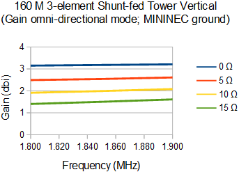 As with any 3-element yagi the gain is maximum at the top of the range while F/B is maximum lower down. Although both suffer once you pass above the frequency of maximum theoretical gain, gain rolls off sooner because radiation resistance is lowest where gain is highest.
The antenna's gain relative to a simple vertical should be considered since it is a useful comparison baseline. Gain was plotted across the same range for the same values of ground loss. Ground loss is less than for the yagi because of the higher radiation resistance. Gain gradually increases with frequency as the driven element's electrical length increases.
The array can be put in omni-directional mode to cover directions other than those available from its reversible yagi modes. This is done by floating or detuning both parasitic elements and switching in a different matching network.
Matching
The feed point resistance of the yagi is quite low, especially with a low loss radial system. A matching network is required to convert the impedance to 50 Ω. I designed a simple L-network using TLW and inserted that into the EZNEC model. The following SWR plot was done for a 5 Ω equivalent ground loss radial system for all elements.

The 2:1 SWR bandwidth is 60 kHz. I targetted 1835 kHz for the best match hoping to achieve the best result. Raising it a little higher may be better. Notice how fast the SWR rises on the high end where gain is maximum and radiation resistance is lowest.
A broader SWR bandwidth can be had with a smaller radial system because its higher loss sums with the radiation resistance to proportionately reduce variation of radiation resistance and reactance across the band. That is a poor reason to skimp on the radials! Better to use a switchable matching network to eke more bandwidth on the high end of the range.
Details of the matching network are not described since every installation will be different and the tools to design networks are readily available. I recommend building the antenna, tuning it and then measure the impedance across the band. The matching network should be designed to achieve the lowest SWR curve across the desired operating range.
Further thoughts
With an excellent radial system this antenna has 5 to 6 db advantage over a simple full-size vertical. That's a lot on top band. It will easily improve contest and DX results. But is it worth it? After all, this is no small antenna: it's big, ugly and expensive. If you already have or are planning some big towers it is certainly worth a look.This antenna only has two directions and we ideally want four (the pattern isn't sharp). The most economical way to add those is with T-top sloping verticals wires supported from the same catenary rope supporting the driven element. These are similar to those in my 80 meter vertical yagi, just like in the original K3LR 160 meter array you can find in ON4UN's Low Band DXing book. Additional mechanical support for the catenary and stronger wire for the additional elements may be needed.
There does remain a concern of interactions with antennas on the tower which could place significant energy into receivers using those antennas. Band pass filters are mandatory. Alternatively the towers can be left as is by dropping wires from the catenary for the parasitic elements. Coupling with the tower and cables will still occur but that may be more managable by, for example, detuning the tower and bonding coax and shielded cables to the tower at several points, or by running them inside the tower. Any coupling that does occur will influence the tuning procedure to a degree that the presented design does not address -- a simple model I built proved to be challenging in this regard, but was not conclusive. Correct tuning may have to be experimentally determined.
In all cases this antenna will require a switching system and control cables to allow direction and mode selection from the shack. There is ample material in the ON4UN book on how to go about it. After the switching system for my 80 meter vertical yagi is completed and in service I'll describe it in the blog and that can be used as a template for the 160 meter yagi.
I'd really like better performance on top band but I cannot realistically assign it more than very low priority. This was an interesting thought experiment that will be filed away. Who knows what the future will bring.
Wednesday, February 6, 2019
2019: Year of the Yagi
 |
| Waiting for spring |
Despite the inward focus it can still be of use to others who could benefit from doing the same, and then measuring their progress at the end of the year. The comparison can be both sobering and instructive.
My ultimate objective is a moderately competitive contest station suitable for both single op and multi op, while also fueling my daily operating habits of DXing and experimenting with new technology and operating aids. It is not intended to be a lifelong project. With some effort the bulk of the "heavy lifting" will be completed in 2019 or early 2020. Since there will be non-radio summertime activities I may not fulfill my entire plan. But it is important to have objectives and a plan to get there.
After failing to fully achieve my 2018 ambitions I remain cautiously optimistic that I can do better in 2019. The major construction project -- a 140' tower -- is more than half raised, and should be complete in early spring. The only substantial mechanical decision to be made with respect to the new tower is whether to go with a conventional heavy-duty rotator or to use my spare prop pitch motor. Construction of the mast and drive system must be complete before the top two tower sections leave the ground.
With that out of the way I can turn my attention to antennas, and antennas means yagis big and small. Indeed, that is the focus of my plan for 2019.
Building yagis
As with most everything in our stations we have a choice between build and buy. Buying can be new or used. Time is limited and none of us can build everything in a large station. I pick my places. One of those places is antenna.
I have booms built for one each of long boom yagis for 20 and 15 meters, and I have most of the material on hand to build identical copies of each. These 4 yagis are slated for the new 140' tower (40 m, more precisely) on these all important contest bands. The lower yagis will be fixed northeast, towards Europe.
Aluminum tubing is available in abundance from just about every industrial metal dealer. The trouble comes when specifying the alloy and the less popular sizes suitable for telescoping elements. For example, one outlet that claims to sell most everything in any length does not actually do so. Alloys are mostly the weaker non-structural and the selection of wall thicknesses and outer diameters is incomplete. Another outlet carries more suitable tubing but only in full 20' and 24' lengths and charges quite a lot for cutting. I would have to cut tubes in their parking lot to fit them in my car!

Boom-to-element brackets are another area of concern. Although straight-forward to design and build it is the fasteners that are expensive. Each alone isn't, but I will require a large quantity.
I am searching for good quality and reasonably prices products which, again, will have to be imported from the US. Importing from the US ought to be simple but often isn't since many dealers do not specialize in international sales and can incur substantial brokerage fees. There are alternatives to get around the problem.
Once construction of the yagis is fully underway I will surely devote a few articles to the subject. Compared to many of the components of a large station yagis are relatively simple things. It's the details that can bog you down.
Tri-banders
With mono-band yagis for the high bands I will have surplus tri-band yagis, all Hy-Gain: TH6, TH7 and Explorer 14. I will likely sell the latter and probably the same for the TH7. I would then find another TH6 and stack them on one of the towers, possibly rotatable through 120°. I would use these at a lower height to cover the US and Caribbean, without risking interactions with the mono-band yagis higher up.
Side mounting these yagis is, in part, why I will replace the TH7 with a TH6. On the TH7 the dual driven elements can easily strike the tower when rotated. Further, the electrical design of the TH7 is not optimal for the CW band segments on 20, 15 and 10 meters. I don't want to mess around redesigning the antenna to do better on CW. The gain and performance is acceptable but not the SWR.
Although not the best antennas these large tri-banders will take a lot of the operating burden from their mono-band cousins, allowing instant switching between directions and still have a powerful signal wherever I need it. It's also far cheaper than alternative but will likely need to be refurbished. Getting the TH6 down from the big tower is necessary no matter what because one of the traps is exhibiting intermittent continuity.
80 meters
My vertical yagi project has been proceeding slowly. So slowly that it's almost been standing still. I further delayed working on the switching system due to the deep snow and cold temperatures. Now that the hours of sunlight are increasing and warmer weather approaches I intend to get going on it.
 |
| 80m vertical yagi switching system - some assembly required |
Ideally it would be ready in time for the upcoming ARRL DX CW weekend, but that is unlikely. I'll leave it fixed on Europe as I did in CQ WW CW. I configure it that way except for Pacific area DXpeditions and North American contests.
The 80 meter vertical yagi should be completed before the warm weather when my attention will shift to other projects.
40 meters
When the TH7 comes off the 21 meter tower (70') my plan is to replace it with the XM240. This would become my short path rotatable yagi for this important contest band, covering the US and more. But before it comes down from its current position at 46 meters (150') on the big tower I need to replace it with another 40 meter yagi.
Therein lies what is perhaps my biggest roadblock this year. I want to build and raise a full size 3-element yagi to go on that tower. That's a large enough project that it may be impossible to manage this year considering everything else that needs to be done. Indeed this antenna is why the prop pitch was installed on that tower.
It's entirely possible that there will be nothing up there in the fall. That is, if I can build a wire yagi pointed at Europe between the two big towers. That way I would not have a unbridgable gap in my 40 meter capability. Alternatively I could purchase another XM240 or similar yagi as a stop gap measure for the next year or two. Should the opportunity arise I may go for it.
10 meters
This is the least of my worries. I do plan stacked yagis for 10 meters on the 40 meter tower, with one 6-element yagi on top of the mast above the planned 40 meter yagi (where the XM240 is currently situated), and one or two more lower down fixed on Europe but preferably rotatable.
With the sunspots not reappearing to boost 10 meter propagation until 2021 this project will be fit in as time is available, after the other projects are completed.
6 meters
No changes are planned this year. The redesigned A50-6 at 24 meters will be my antenna for this year's sporadic E season. The only change will be the transmission line so that I can recover most of the estimated 3 to 4 db loss in the very old run of RG213 I've been using until now. The reason I've delayed replacing it is to save the Heliax I have for runs to and up the big towers.
If that supply problem is not resolved by April I will install a run of LMR400 up the tower from the antenna switch at the bottom. With the recent rewiring the run from there into the shack is a combination of LDF5 Heliax and LMR400, which is good enough for now.
In future years I would like more gain on 6 meters. This would either be accomplished with a longer boom yagi or a stack of two yagis. They will likely require a new tower. I have some thinking to do.
160 meters
I covered my options in a recent article. As a minimum I will replace the current antenna with full height wire vertical and at least double the current 8 radials. Every decibel I can scrape out of a simple and temporary antenna will pay big dividends. This was emphasized by the difficulty I encountered during the recent CQ 160 meter CW contest when marginal conditions kept a large number of QSOs and multipliers just out of reach. I don't want that to happen again.
Longer term I do want to exploit the towers to achieve gain on top band. I have been running models to explore alternative ways to corral them into either a vertical yagi or phased array. In addition to computer models I would need to experiment to ensure using the towers will not cause serious coupling into the tower mounted yagis, and from into the station. It is a solvable problem.
Receive antennas
The short west Beverage is a stopgap until I improve my low band receive capability. At the least I plan to twin the existing northeast Beverage to make it reversible. A north-south reversible Beverage is also likely. These projects could be put off because they are not mandatory until I run high power and attract many weaker stations. It is also not absolutely needed for 80 meters since the vertical yagi has very good directivity. Receive antennas are primarily needed for 160 meters.
A vertical phased array remains a possibility, if only to simplify maintenance and eke out the best directivity and selection of directions. I have not decided. The small number of planned Beverages will prove adequate until the rest of the station is complete. More receive options raises the possibility of diversity reception, which is a powerful technique for copying weak signals.
In the shack
As I demonstrated last month it is possible to do SO2R and multi-op with no automation or filters, for low power contesting. When I acquire an amplifier that must change. I have been putting off this work until it becomes unavoidable. There is also the prospect of more antennas which will exceed the capacity of my current switching system. When my 2019 tower and antenna plan comes to fruition there will be no more putting off the inevitable.
Automated selection of filters and antennas from two operating positions will be needed by the fall contest season. That will be quite a challenge since much of it will need to customized, a hybrid with commercial equipment. The filters will be bought and the switching system designed and developed by me.
I would like to arrange the first multi-op sometime during the next contest season. Station automation is required since it may be too much to ask others to figure out the unique manual control systems I currently employ. Physical rearrangement of the shack will also be necessary so that two people can comfortably operate together. Of all my challenges this will be the easiest to accomplish.
Transceivers are going to change. I expect to sell both the KX3 and FT950. The FTdx5000MP will remain for one operating position and the other will be a K3 or similar high end transceiver. I will still be able to operate QRP by turning the power down to 5 watts (but not on the 5000 which has a minimum power of 10 watts). Although the KX3 is a wonderful rig I am becoming increasingly frustrated by its limitations; it is not suitable as a high performance base station rig.
For competitive use the FT950's DSP filtering is too noisy and rings and the receive audio is noisy. It has been surpassed by subsequent generations of equipment. I have kept it around to experiment with SO2R and as a backup for the main transceiver.
As with previous years my 2019 plan is ambitious. I have set my objectives and now must do my best to achieve them. That I will probably fall short does not deter me from aiming high.
Administrivia
Google has not only abandoned Blogger development they are also in the process of shutting down Google+. The latter is not of concern to me other than it will mess up reader comments and possibly some lesser things. I won't know until it happens. Anonymous comments unfortunately remain prohibited because every time I allow them there is a flood of spam. I apologize for the inconvenience. It's because of this problem that comments are moderated.
As many have discovered, direct email is the best way to reach me. Those I reply to. Comments on articles are routinely approved although I might not reply to those. Blogger may eventually become unusable and I'll have to find a new home. That would be an unwelcome burden and could kill the blog. But for now it's business as usual.
Monday, January 28, 2019
Short Beverage Antenna for 160 Meters
One of the many projects I did not get done in 2018 was putting up more receive antennas for the low bands. The delay is due to its relative priority being lower than transmit antennas, such as my still not quite complete 80 meter vertical yagi.
Up to now I have just the 175 meter long Beverage antenna pointed northeast at Europe. It's a wonderful antenna, although one that requires periodic maintenance. That's a common complaint about Beverages strung through bush and forest. The area was selected because it is far from sources of potential interference and it is only populated by wildlife. The farm fields are easier to work in but would require taking the Beverages down during spring and summer.
 With the upcoming CQ 160 meter contest as motivation I spend some time last week putting up a temporary Beverage pointing west. It is shorter and simpler than what I have planned for a permanent antenna. What it therefore lacks in performance is compensated by the reusability of its components (even the wire) and ease of construction. By "ease" I mean relatively easy compared to alternatives.
The Beverage is ~89 meters long, about the shortest a Beverage for 160 meters can be and still deliver acceptable performance. That length is not randomly chosen. Like yagi booms there are lengths that exhibit peaks in F/B, and therefore directivity and noise attenuation. To demonstrate this I selected three lengths -- 70, 89 and 110 meters -- and modelled them with EZNEC. The impetus for the modelling comes from ON4UN's book Low-band DXing, in which optimum lengths are discussed.
Notice the differences. F/B is significantly better with an 89 meter length. However gain increases (beam width decreases) with length. There is a peak in F/B approximately every multiple of 89 meters; gain continuously increases as the length increases. Gain is not too critical since, if needed, it can be provided with a pre-amp. The length does not have to be precisely 89 meters. A few meters either way has little impact on performance. The small difference in F/B is likely swamped by other variables such as ground quality.
The gain difference is noticable. The modelled gain of the 175 meter Beverage on 160 meters is -10.5 dbi versus -15.1 dbi for the 89 meter Beverage, or -4.5 db worse on the shorter and lower antenna. About -0.5 db of that is due to the lower 1 meter height of this antenna. (There is another -1 db of coax loss, as we'll see later.) The additional loss is enough to make comparisons between the Beverages difficult. Of course the gain is not indicative of the antenna's directivity, and therefore its effect on copy of signals in the target direction.
Feed point

In the spirit of keeping it simple for this temporary antenna the feed point is built into a discarded plastic food container. The clear plastic helpfully shows all of the components, inside and outside, but does confuse which side each is on. The inside only contains the matching transformer. Stainless steel hardware provides studs to attach the Beverage wire and groung wire. I am using UHF connectors since I have them and I don't have type F bulkhead connectors.
The ferrite core and construction are the same as for the northeast Beverage. The turns ratio of 5:2 is a good match between RG6 (70 Ω) and 500 Ω for the antenna. This was tested with a 470 Ω resistor which measure 495 Ω. A better match is possible with a turns ratio of 8:3 but I got frustrated trying to thread more turns through those tiny holes in the BN73-202 binocular core. This is despite using thin AWG 24 insulated wire scrounged from old Cat5 cable.
With the cover on the container it is pretty well watertight when the lid faces up. Otherwise water could seep in around the studs and SO239 connector. Sealant is near useless due to the flexibility of the thin plastic.
Termination
 Driving the ground rods into frozen ground is not fun. After a couple of weeks of extremely cold weather and thin snow cover the frost has penetrated deep. I used a pick axe to remove the top 10 cm of frozen soil. That was enough to hammer the rods through the remainder of the frozen soil into the warmer ground below. However I did encounter rocks that required repeating the process several times until I could get down the full 4'.
I did not use a 470 Ω resistor for the termination. After reviewing material on Beverage antenna construction I realized that I had to compensate for the serial resistance of the ground loss. With a single ground rod this can be exceed 100 Ω even in good soil. I opted for a 330 Ω carbon composition resistor that measure close to 350 Ω (carbon composition resistor increase in value with age). This worked out well when I measured 495 Ω at the feed point from 1.5 MHz through 7.5 MHz.
I kept the construction simple. The resistor is clamped directly to the ground rod. A wire nut connects it to the Beverage wire. Since the wire swings a bit in the breeze I dropped a piece of scrap lumber on it to avoid breakage due to metal fatigue.
The wire tensioner uses a thin nylon rope and a cleat made from a couple of nails pounded in a tree. The feed point end of the wire is secured to a wood fence rail with a nail driven through the insulator. It's simple, cheap and effective.
Beverage wire and siting
I used what was available and long enough: AWG 14 THHN solid copper wire. I have a 300 meter reel from which I've been building my wire antennas. When the Beverage is removed in the spring the wire will be reused for other wire antennas. The insulation allows the wire to sit directly on trees and wood fencing without risk of performance degradation.

The Beverage wire runs along the wood fence line about 1 meter off the ground. There is little to no risk of deer or humans tangling with the wire, other than yours truly. I climb the fence to get to work on the 80 meter array. Because the coax and control cable for the 80 meter antenna cross the fence the Beverage passes close to them. While the Beverage performance should not be affected by the proximity there is a risk 80 meter transmission into the Beverage when operating SO2R on 80 and 160 meters concurrently. I have not tested this yet.
The 150' tower is as close as 25 meters to the Beverage. The tower and antennas are not resonant on 160 meters and the separation should be enough to avoid Beverage pattern distortion even if the tower were resonant. The 80 meter array elements are closer but are not resonant on 160 meters. However if the Beverage is used on 80 meters there is a risk of interaction. First listening tests on 80 meters don't demonstrate cause for concern. The southwest radials get close to the Beverage, although those of the 160 meter vertical (gray circle to the south) are 20 meters from the feed point.
Coax for the northeast Beverage (feed point at the northeast corner of the site map) runs along the fence line on the ground, as far west as the Trylon tower in the house backyard. Therefore they overlap for ~30 meters. This is generally poor practice due to the potential for noise incursion but difficult to avoid in this instance. The RG6 coax for the west Beverage angles south into the hay field, running midway between the 160 meter radials and the Beverage.
Terminating the Beverage further west to reduce all these interaction issues was inadvisable because it would bring the antenna close to the power line that runs through my property (indicated by the gray line). The drop to the house runs underground along the forest of young tree south of the driveway.

These pictures illustrate how the fence is being employed for the west termination (left), supporting the wire and the east feed point. It's as simple as it looks. Laying the line on the fence rails took a couple of hours of walking through the undergrowth with a wire reel, cutting branches and thorns along the way. The deep snow and slush didn't help. The bush on the verges of the hay fields has grown thick over the years due to not being maintained. I am unlikely to change that.
Initial on air testing
I had one evening with the antenna before the CQ 160 contest. Testing was limited due to finding few stations far to the west to properly. I compared it to the vertical itself and the northeast Beverage. At least the large number of Europeans active in preparation for the contest made it easy to establish that the F/B of the west Beverage was reasonably good, perhaps as much as 20 db. That indicates the wire length is performing in accordance with the model.
Later in the evening I heard a W6 and a couple of W7's. The Beverage definitely improved the SNR on those stations. While promising, this was only a tentative assessment. I would have to wait for the contest to have lots of activity and a range of signal levels to better assess its performance. The directivity is better on 80 meters, but again there was a dearth of suitable stations available to get reliable comparison data.
Since I used the full 150 meter roll of RG6 there is an estimated transmission line loss of ~3 db. The extra length was coiled up outside -- it will later become a bidirectional Beverage. The loss is not a great inconvenience other than to make antenna comparisons more difficult. A lesser impact is that the periodic impedance variation with frequency is mostly smoothed away when measured in the shack.
Contest performance testing
Hundreds of stations audible at any time from all over North America and around the world is a fantastic environment in which to conduct an antenna test. Mediocre to poor DX conditions on Friday night were helpful in providing many weak signals for testing, although it was damaging to my score. Late in the evening when west coast activity peaked was the best time to test. It gave me something to do after largely working out the east coast and being unable to work many Europeans.
The TLDR version of its performance: meh! This is about the shortest Beverage you can have on 160 meters and get anything approaching good performance. Although I have not done a direct comparison it is visually apparent on looking at the far field patterns of this and a compact antenna such as a Flag or K9AY array that performance is comparable. One important difference is that the compact antennas require a pre-amp, which in some cases can create noise during SO2R and multi-op contesting.
Despite having a broad azimuth pattern the antenna performed best on VE7 and northern W7 and W0. Reception of W6 stations was slightly improved but very little on W5. I doubt that I would have missed any QSOs during the contest without this antenna but it made easier copy. No Pacific stations were heard. That test will have to wait.
One disadvantage of the overly broad pattern is that the F/S is poor. W2, W3 and W4 stations showed little improvement with this Beverage and were not notched as they are with the longer northeast Beverage. Removing QRM, not just noise, is desirable in a receive antenna. It did reject signals well off the back, but all I have off the back is Europe and, sadly, there was no QRM from that direction.
Initial tests on 80 meters are promising. Directivity is superior to that on 160 meters due to the antenna being twice as long relative to wavelength. It has been used just once in daily DXing, during a sunrise Pacific opening (I don't often wake up early enough for these!). It made a modest improvement on VK3 and E5 signals, which are more southwest than west from here. I suspect that the modest result is due to atmospheric QRN predominantly coming from the southwest. But I could be wrong.
There are upcoming contests where I expect it to assist with adding multipliers on 80 meters. As yet I have nothing conclusive to report about performance on 40 meters. Another reception tool would be welcome on 40 due to the poor directivity of the XM240.
Future plan
This experimental Beverage antenna will come down in the spring. As an experiment is has already proven fruitful and I expect to get more out of it for the rest of the winter. The wire and coax will be recycled into other antennas and the transformer will likely see service in another Beverage. The plastic container will be discarded (recycled) since it won't survive the weather for long.
Many low band enthusiasts have replaced their Beverages with switchable vertical arrays, which can achieve equal or better directivity with a smaller footprint. But they're more complex, requiring hybrid combiners, phasing harnesses and amplifiers among other specialized components. Most opt for commercial products. As I said earlier, these arrays need to be well separated from transmit antennas to avoid the potential for grief from the pre-amps.
I am on the fence regarding Beverages versus vertical arrays. This is a choice I'll have to made by the fall. Regardless of that decision I am very likely to twin the northeast Beverage to make it bi-directional. Ultimately that may be my only Beverage.
Up to now I have just the 175 meter long Beverage antenna pointed northeast at Europe. It's a wonderful antenna, although one that requires periodic maintenance. That's a common complaint about Beverages strung through bush and forest. The area was selected because it is far from sources of potential interference and it is only populated by wildlife. The farm fields are easier to work in but would require taking the Beverages down during spring and summer.
With the upcoming CQ 160 meter contest as motivation I spend some time last week putting up a temporary Beverage pointing west. It is shorter and simpler than what I have planned for a permanent antenna. What it therefore lacks in performance is compensated by the reusability of its components (even the wire) and ease of construction. By "ease" I mean relatively easy compared to alternatives.The Beverage is ~89 meters long, about the shortest a Beverage for 160 meters can be and still deliver acceptable performance. That length is not randomly chosen. Like yagi booms there are lengths that exhibit peaks in F/B, and therefore directivity and noise attenuation. To demonstrate this I selected three lengths -- 70, 89 and 110 meters -- and modelled them with EZNEC. The impetus for the modelling comes from ON4UN's book Low-band DXing, in which optimum lengths are discussed.
Notice the differences. F/B is significantly better with an 89 meter length. However gain increases (beam width decreases) with length. There is a peak in F/B approximately every multiple of 89 meters; gain continuously increases as the length increases. Gain is not too critical since, if needed, it can be provided with a pre-amp. The length does not have to be precisely 89 meters. A few meters either way has little impact on performance. The small difference in F/B is likely swamped by other variables such as ground quality.
The gain difference is noticable. The modelled gain of the 175 meter Beverage on 160 meters is -10.5 dbi versus -15.1 dbi for the 89 meter Beverage, or -4.5 db worse on the shorter and lower antenna. About -0.5 db of that is due to the lower 1 meter height of this antenna. (There is another -1 db of coax loss, as we'll see later.) The additional loss is enough to make comparisons between the Beverages difficult. Of course the gain is not indicative of the antenna's directivity, and therefore its effect on copy of signals in the target direction.
Feed point

In the spirit of keeping it simple for this temporary antenna the feed point is built into a discarded plastic food container. The clear plastic helpfully shows all of the components, inside and outside, but does confuse which side each is on. The inside only contains the matching transformer. Stainless steel hardware provides studs to attach the Beverage wire and groung wire. I am using UHF connectors since I have them and I don't have type F bulkhead connectors.
The ferrite core and construction are the same as for the northeast Beverage. The turns ratio of 5:2 is a good match between RG6 (70 Ω) and 500 Ω for the antenna. This was tested with a 470 Ω resistor which measure 495 Ω. A better match is possible with a turns ratio of 8:3 but I got frustrated trying to thread more turns through those tiny holes in the BN73-202 binocular core. This is despite using thin AWG 24 insulated wire scrounged from old Cat5 cable.
With the cover on the container it is pretty well watertight when the lid faces up. Otherwise water could seep in around the studs and SO239 connector. Sealant is near useless due to the flexibility of the thin plastic.
Termination
 Driving the ground rods into frozen ground is not fun. After a couple of weeks of extremely cold weather and thin snow cover the frost has penetrated deep. I used a pick axe to remove the top 10 cm of frozen soil. That was enough to hammer the rods through the remainder of the frozen soil into the warmer ground below. However I did encounter rocks that required repeating the process several times until I could get down the full 4'.
I did not use a 470 Ω resistor for the termination. After reviewing material on Beverage antenna construction I realized that I had to compensate for the serial resistance of the ground loss. With a single ground rod this can be exceed 100 Ω even in good soil. I opted for a 330 Ω carbon composition resistor that measure close to 350 Ω (carbon composition resistor increase in value with age). This worked out well when I measured 495 Ω at the feed point from 1.5 MHz through 7.5 MHz.
I kept the construction simple. The resistor is clamped directly to the ground rod. A wire nut connects it to the Beverage wire. Since the wire swings a bit in the breeze I dropped a piece of scrap lumber on it to avoid breakage due to metal fatigue.
The wire tensioner uses a thin nylon rope and a cleat made from a couple of nails pounded in a tree. The feed point end of the wire is secured to a wood fence rail with a nail driven through the insulator. It's simple, cheap and effective.
Beverage wire and siting
I used what was available and long enough: AWG 14 THHN solid copper wire. I have a 300 meter reel from which I've been building my wire antennas. When the Beverage is removed in the spring the wire will be reused for other wire antennas. The insulation allows the wire to sit directly on trees and wood fencing without risk of performance degradation.
The Beverage wire runs along the wood fence line about 1 meter off the ground. There is little to no risk of deer or humans tangling with the wire, other than yours truly. I climb the fence to get to work on the 80 meter array. Because the coax and control cable for the 80 meter antenna cross the fence the Beverage passes close to them. While the Beverage performance should not be affected by the proximity there is a risk 80 meter transmission into the Beverage when operating SO2R on 80 and 160 meters concurrently. I have not tested this yet.
The 150' tower is as close as 25 meters to the Beverage. The tower and antennas are not resonant on 160 meters and the separation should be enough to avoid Beverage pattern distortion even if the tower were resonant. The 80 meter array elements are closer but are not resonant on 160 meters. However if the Beverage is used on 80 meters there is a risk of interaction. First listening tests on 80 meters don't demonstrate cause for concern. The southwest radials get close to the Beverage, although those of the 160 meter vertical (gray circle to the south) are 20 meters from the feed point.
Coax for the northeast Beverage (feed point at the northeast corner of the site map) runs along the fence line on the ground, as far west as the Trylon tower in the house backyard. Therefore they overlap for ~30 meters. This is generally poor practice due to the potential for noise incursion but difficult to avoid in this instance. The RG6 coax for the west Beverage angles south into the hay field, running midway between the 160 meter radials and the Beverage.
Terminating the Beverage further west to reduce all these interaction issues was inadvisable because it would bring the antenna close to the power line that runs through my property (indicated by the gray line). The drop to the house runs underground along the forest of young tree south of the driveway.

These pictures illustrate how the fence is being employed for the west termination (left), supporting the wire and the east feed point. It's as simple as it looks. Laying the line on the fence rails took a couple of hours of walking through the undergrowth with a wire reel, cutting branches and thorns along the way. The deep snow and slush didn't help. The bush on the verges of the hay fields has grown thick over the years due to not being maintained. I am unlikely to change that.
Initial on air testing
I had one evening with the antenna before the CQ 160 contest. Testing was limited due to finding few stations far to the west to properly. I compared it to the vertical itself and the northeast Beverage. At least the large number of Europeans active in preparation for the contest made it easy to establish that the F/B of the west Beverage was reasonably good, perhaps as much as 20 db. That indicates the wire length is performing in accordance with the model.
Later in the evening I heard a W6 and a couple of W7's. The Beverage definitely improved the SNR on those stations. While promising, this was only a tentative assessment. I would have to wait for the contest to have lots of activity and a range of signal levels to better assess its performance. The directivity is better on 80 meters, but again there was a dearth of suitable stations available to get reliable comparison data.
Since I used the full 150 meter roll of RG6 there is an estimated transmission line loss of ~3 db. The extra length was coiled up outside -- it will later become a bidirectional Beverage. The loss is not a great inconvenience other than to make antenna comparisons more difficult. A lesser impact is that the periodic impedance variation with frequency is mostly smoothed away when measured in the shack.
Contest performance testing
Hundreds of stations audible at any time from all over North America and around the world is a fantastic environment in which to conduct an antenna test. Mediocre to poor DX conditions on Friday night were helpful in providing many weak signals for testing, although it was damaging to my score. Late in the evening when west coast activity peaked was the best time to test. It gave me something to do after largely working out the east coast and being unable to work many Europeans.
The TLDR version of its performance: meh! This is about the shortest Beverage you can have on 160 meters and get anything approaching good performance. Although I have not done a direct comparison it is visually apparent on looking at the far field patterns of this and a compact antenna such as a Flag or K9AY array that performance is comparable. One important difference is that the compact antennas require a pre-amp, which in some cases can create noise during SO2R and multi-op contesting.
Despite having a broad azimuth pattern the antenna performed best on VE7 and northern W7 and W0. Reception of W6 stations was slightly improved but very little on W5. I doubt that I would have missed any QSOs during the contest without this antenna but it made easier copy. No Pacific stations were heard. That test will have to wait.
One disadvantage of the overly broad pattern is that the F/S is poor. W2, W3 and W4 stations showed little improvement with this Beverage and were not notched as they are with the longer northeast Beverage. Removing QRM, not just noise, is desirable in a receive antenna. It did reject signals well off the back, but all I have off the back is Europe and, sadly, there was no QRM from that direction.
Initial tests on 80 meters are promising. Directivity is superior to that on 160 meters due to the antenna being twice as long relative to wavelength. It has been used just once in daily DXing, during a sunrise Pacific opening (I don't often wake up early enough for these!). It made a modest improvement on VK3 and E5 signals, which are more southwest than west from here. I suspect that the modest result is due to atmospheric QRN predominantly coming from the southwest. But I could be wrong.
There are upcoming contests where I expect it to assist with adding multipliers on 80 meters. As yet I have nothing conclusive to report about performance on 40 meters. Another reception tool would be welcome on 40 due to the poor directivity of the XM240.
Future plan
This experimental Beverage antenna will come down in the spring. As an experiment is has already proven fruitful and I expect to get more out of it for the rest of the winter. The wire and coax will be recycled into other antennas and the transformer will likely see service in another Beverage. The plastic container will be discarded (recycled) since it won't survive the weather for long.
Many low band enthusiasts have replaced their Beverages with switchable vertical arrays, which can achieve equal or better directivity with a smaller footprint. But they're more complex, requiring hybrid combiners, phasing harnesses and amplifiers among other specialized components. Most opt for commercial products. As I said earlier, these arrays need to be well separated from transmit antennas to avoid the potential for grief from the pre-amps.
I am on the fence regarding Beverages versus vertical arrays. This is a choice I'll have to made by the fall. Regardless of that decision I am very likely to twin the northeast Beverage to make it bi-directional. Ultimately that may be my only Beverage.
Subscribe to:
Posts (Atom)