Although this antenna may never be built the concepts it contains are useful enough to be written up. It may give readers ideas of their own. Keep in mind that while few hams have huge towers the design can be scaled to higher bands; for example, ~15 to 25 meter tall towers on 80 meters.
Antenna topology
My big towers are 60 meters apart, with a line through them that points approximately northeast and southwest. For this region that covers the two most productive directions for contests: Europe and the US midwest and southwest. A reversible 3-element vertical yagi would do wonders for contest scores and top band DXing. With the towers detuned the driven element becomes an omni-directional vertical. Unlike my 80 meter array the parasitic elements (towers) cannot be floated, only detuned on 160 meters.

To simplify the model I made both towers 43 meters tall with a capacity hat to emulate the yagis at the top. The unfinished tower will in actuality be a slightly shorter 41 meters. The capacity hat is a rough stand-in for a mast and yagis. As we will see this is not critical since the towers will be tuned to the desired resonance. The physical height is more important in setting the aperture of the element and therefore the mutual impedances between elements.
In previous models I went simpler yet by making the physical height the estimated electrical length of the tower. Each capacity hat has 4 arms of 6 meters length and 25 mm diameter. This is a good enough analogue to ensure the shunt feed design can be adjusted to the required resonant frequency.
As with any reversible yagi the driven element should be centred. The symmetry ensures equivalent behaviour when reversed, greatly simplifying switching, tuning and matching. Optimum performance requires the driven element to be offset toward the reflector. An ambitious builder could drop two wire vertical elements from the catenary and switch between them and detune the unused wire, thus achieve slightly more gain and F/B. I will not be so ambitious in the present design.
A "boom" length of 60 meters (0.365λ) is just about ideal for optimal performance of a 3-element yagi. It is no accident that my towers are this far apart; it was not the primary reason, but it was a consideration. Since it isn't easy to move a tower once it's been planted in the ground some forethought is recommended.
Ground model
My modelling software, EZNEC, allows a few alternative ground models. Vertical antennas and arrays can be greatly simplified by eschewing radials entirely by replacing them with a resistor that connects the vertical to ground. The resistor value should be set to the estimated equivalent ground resistance.
NEC2 does not support wire connections to "real" ground. Instead we must use MININEC ground, which for purposes of calculating the near field assumes ground is a perfect ground plane: zero loss and infinite in extent. Its equivalent resistance is 0 Ω, hence the need to insert a resistor. Generating the far field pattern relies on the specified ground parameters -- dielectric constant and conductivity -- which we certainly need, but it is not used to calculate the near field.
Real radial systems have non-zero equivalent resistance and are therefore lossy. We want the most extensive radial system we can manage to minimize loss. In a yagi the loss is higher than in a simple vertical antenna because the radiation resistance is lower, and the radiation resistance and ground resistance are in series. Achieving an equivalent resistance lower than 5 Ω requires at least 50 to 60 λ/4 radials. With 8 radials the equivalent resistance is rarely better than 15 Ω, even over very good ground quality. The more extensive the radial system the less real ground affects loss.
Perfect ground is a true non-resonant ground plane. A lesser system made of finite length wires will influence antenna resonance. This effects the tuning of the elements, which we compensate for in the tuning procedure. If you later add more radials in future the elements must be retuned. The resonance effect of radial count and length was discussed in an earlier article. That and other work the article references can guide the physical design of an effective radial system.
Shunt feed tuning
 Tuning an electrically long tower can require a more complex network than a gamma match. Fortunately the towers are parasitic elements so all we need to tune for is the reactance, leaving the resistance part of the impedance to find its own level. Not that the complex impedance is without impact, only that we can work around it.
I found that a 20 meter long gamma rod of AWG 12 wire spaced 1 meter from the tower (centre-to-centre) worked well. In the model the rod is 19 meters long since it begins 1 meter above ground.
Feel free to experiment with other arrangements. I deliberately chose these 1 meter values to be equal to the segment length of all wires, thus assuring the best accuracy of NEC2 calculations. Consistent with this constraint, longer wires are all an integral number of meters, and equal to the segment count. Notice that the gamma rod is a small fraction of a wavelength from the tower, a case where it is critical to have their segments aligned.
There are loads in the tower's bottom segment (also 1 meter long) and the gamma rod's bottom segment for the equivalent ground resistance and gamma capacitor, respectively. Were the tower fed by transmission line the feed point would be at the bottom conductive spacer. We will only put a source there temporarily when tuning the element. In the model the source is centred on the spacer because it has only 1 segment.
When I need to float vertical elements in models I ordinarily lift the wire bottom off the ground. Because that is awkward with a shunt feed I instead temporarily raise the resistance to 100,000 Ω. This works very well to isolate the element from ground. When actually tuning the tower neither of these methods may work. The tower base itself may behave as an Ufer ground, and the bundle of coax and control cables are a long radial. Instead try shorting the gamma capacitor, adding a parallel capacitor or disconnecting the gamma rod. I can't make a firm recommendation until I try it myself.
Tuning the parasites
Setting the self-resonance of the parasitic elements is the remaining critical factor to making the antenna work. This is far easier to explore with a computer model than on a real antenna.
First I selected a centre frequency of 1830 kHz, which is a little high for general CW DXing but about right for contesters who typically use the range 1800 to 1880 kHz for CW. In ITU region 1 it may be desirable to raise the centre frequency since 1810 is the lowest frequency allowed. I am also not interested in SSB on 160 meter, so I am not concerned that the bandwidth is not enough to function higher in the band.
As an initial estimate of the desired tuning I chose self-resonant frequencies of 1738 kHz for the reflector and 1922 kHz for the director. These are 5% offsets which typically offer a good compromise between gain and SWR bandwidth. As we'll see my choice worked out pretty well. For this exercise I did not try and compare other offsets. If I ever consider building the antenna I may do so.
The tuning procedure for the shunt fed tower is straight-forward. The driven element and the other parasitic element are effectively floated by inserting a 100,000 Ω resistance at their bases. Calculating element currents confirmed they are negligible in the floated elements. The source is placed in the wire connecting the bottom of the gamma rod to the tower, as was described in the previous section.
The self-resonance is set by experimentally adjusting the gamma capacitor. We are looking for an impedance of R + j0 Ω; that is, self-resonance is the frequency where X = 0. The R value is not critical to the tuning of the parasitic element. The capacitor settings were 310 pf for the reflector (1738 kHz) and 227 pf for the director (1922 kHz). In a real antenna a variable capacitor can be used to tune the element. Because tuning is sensitive (~0.5 pf per 1 kHz) the capacitor shaft must be well insulated to prevent your hand from effecting the tuning. Once tuned the variable capacitor can be replaced by a fixed capacitor.
A small difficulty
With the model fully done I tested it. All was not well, though not in a totally surprising manner. The yagi's performance data were favourable, but for a centre frequency of 1880 kHz. The parasitic element shunt feed -- gamma rod and capacitor -- is doing something more than just achieving self-resonance at the assigned frequencies.
This is not the first time I've observed this behaviour. Performance bandwidth offset appears to be a feature of yagis using loaded elements. This is certainly true of short elements, and in this case it is occurring with electrically long elements. The 50 kHz offset is 2.7% of 1830 kHz, or about half of the parasitic element self-resonance offset from the intended centre frequency. That's a large error.
I increased the gamma capacitor values on both towers in tandem (and in proportion) until I found the settings that centred the yagi on 1830 kHz. These are 340 pf and 276 pf for the reflector and director, respectively. I floated the other elements to discover the new self-resonance frequencies: 1697 kHz and 1875 kHz. Although quite different their ratios are identical, as they should be.
 The reason for the different offset for loaded elements requires understanding how the parasitic elements in a yagi perform their task. It is not due to their self-resonant frequencies; what matters is the phase shift, and that is determined by the element's reactance at the yagi's operating frequency.
The self resonant frequency varies with degree and type of element loading. Longstanding rules of thumb for tuning yagi elements only apply to unloaded elements. In reality the self resonant frequency is unimportant, only serving as a tuning guide. With modern high accuracy antenna analyzers with can dispense with it entirely.
Performance
Ground loss is an unavoidable feature of any vertically polarized antenna located close to ground. This goes double for a low impedance antenna like a yagi. Again, recall that the equivalent resistance of the ground loss is in series with the antenna's radiation resistance and conductor resistance. The lower the radiation resistance the greater is the proportion of the applied power that is dissipated in the loss resistances.
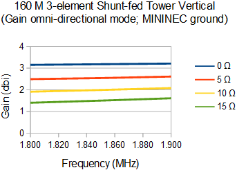
 I modelled the performance over a range of resistances, from 0 Ω (perfect ground) up to 15 Ω (typically 8 to 10 λ/4 radials over medium to good ground), in steps of 5 Ω. The impact of the radial system is starkly illuminated. Getting below 5 Ω requires at least 40 radials. Depending on your ambitions it can be very good investment.
It is assumed that the radial system is identical for all 3 elements. This isn't necessary, and it can be sensible to make the radial system for the driven element better than those for the parasitic elements. Current, and therefore potential loss, is greater in the driven element than either of the parasitic elements. This was demonstrated in more detail in the design of the 80 meter 3-element vertical yagi I recently built so I won't repeat it here.
 As with any 3-element yagi the gain is maximum at the top of the range while F/B is maximum lower down. Although both suffer once you pass above the frequency of maximum theoretical gain, gain rolls off sooner because radiation resistance is lowest where gain is highest.
The antenna's gain relative to a simple vertical should be considered since it is a useful comparison baseline. Gain was plotted across the same range for the same values of ground loss. Ground loss is less than for the yagi because of the higher radiation resistance. Gain gradually increases with frequency as the driven element's electrical length increases.
The array can be put in omni-directional mode to cover directions other than those available from its reversible yagi modes. This is done by floating or detuning both parasitic elements and switching in a different matching network.
Matching
The feed point resistance of the yagi is quite low, especially with a low loss radial system. A matching network is required to convert the impedance to 50 Ω. I designed a simple L-network using TLW and inserted that into the EZNEC model. The following SWR plot was done for a 5 Ω equivalent ground loss radial system for all elements.

The 2:1 SWR bandwidth is 60 kHz. I targetted 1835 kHz for the best match hoping to achieve the best result. Raising it a little higher may be better. Notice how fast the SWR rises on the high end where gain is maximum and radiation resistance is lowest.
A broader SWR bandwidth can be had with a smaller radial system because its higher loss sums with the radiation resistance to proportionately reduce variation of radiation resistance and reactance across the band. That is a poor reason to skimp on the radials! Better to use a switchable matching network to eke more bandwidth on the high end of the range.
Details of the matching network are not described since every installation will be different and the tools to design networks are readily available. I recommend building the antenna, tuning it and then measure the impedance across the band. The matching network should be designed to achieve the lowest SWR curve across the desired operating range.
Further thoughts
 With an excellent radial system this antenna has 5 to 6 db advantage over a simple full-size vertical. That's a lot on top band. It will easily improve contest and DX results. But is it worth it? After all, this is no small antenna: it's big, ugly and expensive. If you already have or are planning some big towers it is certainly worth a look.
This antenna only has two directions and we ideally want four (the pattern isn't sharp). The most economical way to add those is with T-top sloping verticals wires supported from the same catenary rope supporting the driven element. These are similar to those in my 80 meter vertical yagi, just like in the original K3LR 160 meter array you can find in ON4UN's Low Band DXing book. Additional mechanical support for the catenary and stronger wire for the additional elements may be needed.
There does remain a concern of interactions with antennas on the tower which could place significant energy into receivers using those antennas. Band pass filters are mandatory. Alternatively the towers can be left as is by dropping wires from the catenary for the parasitic elements. Coupling with the tower and cables will still occur but that may be more managable by, for example, detuning the tower and bonding coax and shielded cables to the tower at several points, or by running them inside the tower. Any coupling that does occur will influence the tuning procedure to a degree that the presented design does not address -- a simple model I built proved to be challenging in this regard, but was not conclusive. Correct tuning may have to be experimentally determined.
In all cases this antenna will require a switching system and control cables to allow direction and mode selection from the shack. There is ample material in the ON4UN book on how to go about it. After the switching system for my 80 meter vertical yagi is completed and in service I'll describe it in the blog and that can be used as a template for the 160 meter yagi.
I'd really like better performance on top band but I cannot realistically assign it more than very low priority. This was an interesting thought experiment that will be filed away. Who knows what the future will bring.
No comments:
Post a Comment
All comments are moderated, and should appear within one day of submission.