Wednesday, July 30, 2025

30 Meter Delta Loop

I have often lamented that I have no antennas for the WARC bands: 30, 17 and 12 meters. Making or buying antennas for these bands is easy enough, it's just that I primarily focus on the HF contest bands and I don't want to crowd the towers and create unwanted interactions. I have relied for years on antennas that can be matched with a rig ATU (or the wide range of a manually-tuned tube amp), and kept pushing off better performing antennas for those bands.

I can get away with it since many of my antennas are high. Height can compensate for poor efficiency and pattern. I do pretty well in the DX pile ups on those bands. Nevertheless it is a gap in my station. In the heat of summer and while waiting for the hay to be harvested I decided to undertake construction of a simple 30 meter antenna. 

Although it's simple, it is worth an article. The reason is that many of the mechanical and electrical issues I dealt with are commonly encountered by hams choosing, designing and building antennas. Hopefully this somewhat lengthy article will prove helpful to some readers. 

I had several objectives for the antenna's design and deployment:

  • DX friendly: I operate the WARC bands solely to chase DX. That means low elevation angles.
  • Omni-directional: Directionality requires rotation or electrical direction switching, which is far more investment than I want for a simple antenna that will not see heavy use.
  • Interaction: My contest band antennas have priority. I won't tolerate interactions (which are almost always detrimental) from this antenna.
  • Support: The main towers are in a hay field. I need the antenna to be entirely off the ground, including supports, so that tractors can freely drive beneath it.
  • Simplicity: I have enough maintenance challenges that I do not want this new antenna to create a lot of unwanted work in the future.

My choice was a vertically polarized delta loop, fed ¼ of the side length up from a bottom corner. This is a common method to achieve vertical polarization in a delta loop. Elevation angle is low, it's omni-directional, doesn't interact with horizontal yagis, and it's simple.

In this model, the delta loop is 1 meter from tower centre and the bottom is 5 meters high -- as built, the antenna is 0.7 meters from tower centre and 6 meters high. That places the apex at about 15 meters, about 8 meters below the lower 5-element yagi of the 20 meter stack. There is one guy threading the delta loop since the lowest guy station is at ~30' (9 m). 

I modelled the tower as a long, thick vertical wire. As for shunt feeding the tower on 160 meters, I had to estimate the effective (electrical) height to approximate capacitance loading of the several yagis. I omitted the guys since they are broken into short non-resonant sections and likely have a small effect. Longer guy segments are located far from the tower and will not affect the delta loop even if there is near resonance at 10.1 MHz. I am more attentive to the effects for a directional antenna since the pattern nulls are easily perturbed.

The tower affects both pattern and resonance. It will still work if placed snug against the tower -- with suitable insulation since that's a high voltage node on the loop -- but will be detuned. If placed further outboard it can become difficult to install and maintain, and the pattern becomes more directional. I wrote about these parameters long long ago.

Rather than ask you to interpret those old words, here are a few notes to keep in mind:

  • I used NEC5. Although accuracy is not critical for this antenna, the close spacing of the delta loop and tower is challenging for NEC2. There is no good way to align wire segments as NEC2 requires. Resonance dropped 500 kHz in NEC5 compared to NEC2. From my field measurements while building this antenna, NEC5 better reflects reality.
  • The electrical height of the tower affects antenna resonance a small amount so it is not critical. Other factors dominate this antenna's behaviour.
  • The closer the delta loop and tower the more omni-directional the pattern and the lower the resonant frequency. The first makes sense since with closer spacing the induced current will be closer in amplitude and phase.
  • Why the strong coupling? Look at the current plot (above left). For a vertically polarized delta loop the voltage nodes (current nulls) are at the two points where the loop and tower are closest and therefore coupling greatest. This is a critical component of Moxon design, as one example. For a delta loop we need to be aware of the coupling if only because it affects antenna dimensions and demands good insulators at bottom centre and apex.
My initial estimate for the loop perimeter length was far off! I neglected to account for the above effects, opting for extra length and then trimming, and I was misled by my initial use of NEC2 within EZNEC. The initial test placed the resonance at 9.0 MHz or more than 10% long. Following up with NEC5 gave a better estimate. Trimming came later. The discussion about the SWR below was using NEC2, which caused several issues, as we'll see.

30 meters is only 50 kHz wide (0.5%) so it is easy to achieve a low SWR across the band, as the NEC2 model's SWR demonstrates. The matching network is a λ/4 transformer made from a 4.9 meter length of 75 Ω coax, included in the EZNEC model. The NEC2 unadjusted feed point impedance is about 115 Ω, which is typical for a full wave loop. The feed point is ¼ leg length (2.5 m) from a bottom corner. If you prefer a mix of vertical and horizontal radiation, a typical choice is to feed the antenna at a bottom corner. Expect a small impedance change, though not enough to justify a different matching network.

That's enough for now about the NEC2 model. Let's move onto construction before dealing with the model errors. Despite being a simple antenna there are several potential trouble points to be considered.

The bottom of the delta loop is made from aluminum tubing. This was done to meet the criterion of no ground anchors. I chose a couple of long tapered surplus yagi elements from my aluminum stock and spliced the inner 1" OD tubes with a 1.315" pipe. It's about 9.5 meters long -- the 3 sides add up to about 30 meters, or 1 wavelength). 

Surplus #12 insulated wire from a decades-old wire antenna was used for the two sides. The EZNEC wires include the insulation since the lower velocity factor shortens the required length, typically 2% (VF of 0.98). As is typically recommended for wire antennas, I cut the wires a little long. They can be trimmed to bring the antenna into resonance where you want.

The sides of the loop pull up the drooping long bottom tubing and provide tension to the structure. The tower bracket keeps the bottom in position and prevents it from rotating in the wind (picture and description further below). The ABS pipe insulates the bracket from the antenna. A good insulator is needed since the centre of the bottom side is at a voltage node.

A vertically-polarized full-wave loop doesn't have to be high to work well. As you take it higher there is more radiation at higher elevation angles and that is usually (but not always!) less than ideal for DXing. However, ground loss increases at lower heights. There's a tradeoff. 

I had to choose a height that minimized potential interaction with the 20 meter yagi up 23 meters while allowing clearance for farm machinery. My initial choice of 4.5 meters was increased to 6 meters to be certain of avoiding collisions. It is still well below the bottom 20 meter yagi.

The other interaction consideration is the cage gamma rod alongside the tower. The tower is shunt fed on 160 meters. There will likely be a tuning impact on 160 that I'll have to compensate for. Since the radials are removed for farming operations that can't be done yet.

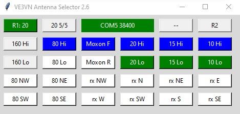
I temporarily connected the delta loop to the 160 meter transmission line and made the required changes in my antenna selector software. By fall, when the 160 meter antenna is back in service, I'll add an auxiliary switch so that the antennas can share the transmission line. There is no foreseeable case where both antennas will be used at the same time.

I made brackets in my workshop for connecting the wire sides of the loop to the aluminum tubing bottom. Small strips of aluminum are held to the tube by hose clamps. There is a lip to keep the strips from slipping out. The wires are connected to the slanted upward end of the bracket by ¼" stainless bolt. Smaller bolts are strong enough but the smaller washers are insufficiently wide for wrapping #12 wire. The wire ends are looped and tinned for strength and to protect against corrosion, respectively.

The brackets can be slid along the tube for fine adjustment of antenna resonance without having to cut the wires. That feature came in useful.

The ¼λ transformer is made from RG59. It is found cheaply at local flea markets and is sufficient for the lower power permitted on 30 meters. It might handle a kilowatt but I don't intend to find out! The coax is coiled into a scramble wound CMC (common mode choke). It's less than ideal but good enough for a simple antenna like this one. Use a better choke if you prefer, but take into account its weight on the wire side of the loop.

When I modelled the antenna I added wires to simulate common mode on the outer side of the coax shield going down to the ground. To my surprise it had a deleterious impact on the pattern. Modelling the coax outer shield proved beneficial since even simple antennas can behave in ways you might not expect.

The RG59 solid centre conductor is fragile so I didn't want it swinging in the wind. Coiling the coax and binding it to the feed point insulator helps to avoid trouble. There is no wind induced flexing of either the open wire ends of the RG59 or the antenna wires. I added a short length of stranded and tinned wire to the centre conductor to further protect it should there be any unexpected movement. Weatherproofing of the open RG59 end was done after the picture was taken.

The LMR400 feed line is unsupported between the feed point and the tower. One advantage of LMR400 in this application is that it is lighter than many alternatives, included the heavier RG213. Their wind loads are equal and that may be a factor of coax choice if strong wind is a concern. RG58 might be a better choice for that case but, again, power handling might be an issue for bands other than 30 meters.

When the wire sides were draped over the tower guy station and connected to the bottom section, the bottom corners of the loop were slightly off the ground. This was my chance to do a "sanity" check. It may seem odd if you've never seen it done before, I connected the analyzer and swept the SWR over a wide range. 

Obviously the antenna is nowhere near functional in this state! However, this test will indicate whether the antenna is functional. There will be excess ground loss and significantly lowered resonance since it is sitting on the ground, and the apex is draped over a conductor (the guy station anchor). The SWR dip down to about 4 at 8 MHz was a satisfactory result. Had there been no dip around that frequency I would have checked all the connections to see if there was a mistake. I've done the same test with tri-band yagis propped up a few feet above ground.

Confident that the antenna was approximately correct, I weatherproofed the exposed conductors and capped the coax connector. Raising the delta loop for a proper test was delayed a few days while I attended to other matters during a bout of extreme heat (well, for us). Working outdoors was unpleasant.

The apex of the raised delta loop is a convenient distance below the long tube that supports the top of the 160 meter gamma rod. So that became the upper support. Rather than tying the dacron rope directly to the wire, I routed the wire over a large thimble I pulled from my junk box. The thimble avoids a sharp bend in the wire and makes it easy to level the loop by sliding the wire over it. Since I was working alone I did it by observing the antenna's shadow. 

Under tension the friction is high enough that the insulated wire is unlikely to shift. But it wouldn't be a bad idea to connect the wires on both sides of the thimble to limit motion. Don't pinch the wire since that can alter the tuning. Instead use a length of PVC or other plastic rod. Make it longer and the interior angle can be raised from 45° to the ideal 60°. The acute angle is due to wire sag. I can't increase wire tension any further since that pulls up the ends of the tube bottom side.

The support rope is looped over the gamma rod support tube several times. Tension and friction prevent the rope creeping along the tube. The rope is loosely tied to the tower to prevent it blowing in the wind. It is not a truss for the tube, as it may appear in the picture; the tube is strong enough on its own.

This is a view from the ground of the bottom side bracket. The hardware store utility angle is not strong enough for this application but it was handy and didn't require that I do any drilling. There is very little weight on the bracket since the apex support rope takes much of the strain. However, the wind load on a 10 meter long tapered tube is a danger. The ropes on either side of the ABS pipe provide lateral support.

If the antenna works well I'll replace the bracket with a stronger one. There is no rush. 

When I tested the antenna in its final configuration it resonated at 9 MHz. That's more than 10% low! After further tests and modelling using NEC5 (as discussed earlier) I lopped 1 meter off each of the two sides -- shortening the loop by 7%. That's less than 10% but it is better not to overshoot when trimming wires. With several factors that influence resonance there is more than one way to reaching the desired endpoint.

Trimming raised the resonant frequency to 9.7 MHz, which is indeed about 7%. For the final adjustment I slid the wire brackets at the ends of the bottom tubes inward by 65 cm. That put the SWR curve where I wanted it. 

The SWR is unfortunately difficult to read in the adjacent picture. The centre of the display is 10.1 MHz. The SWR is about 1.8 mid-band. I took the measurement with a 50' roll of LMR400 that was looped over my shoulder. The open run to the feed point drooped more than was ideal. 

The SWR improved when the cable was properly dressed and routed down the tower face. However it was still no better than 1.5. When I returned to EZNEC I discovered the reason. I had neglected to rerun the SWR plot using NEC5. NEC2 did not correctly calculate the impedance due to close coupling to the tower.

The tight coupling lowered the feed point impedance to between 75 and 80 Ω. That is much lower than the 115 Ω calculated by NEC2. The RG59 ¼λ transformer is doing nothing at all since its nominal impedance is the same as the antenna. I could do away with it but it's still handy as a common mode choke.

The insects and heat were insane so I decided that this was close enough. The rig put power into the antenna just fine without the ATU.

That's the completed antenna. There is enough tension in the support rope to pull up the ends of the bottom side a small amount. That adds stability to the antenna. Also notice that the coax is routed so that it comes off the side at close to a right angle to reduce coupling. It can't be entirely eliminated since the coax must traverse the interior of the loop when fed for vertical polarization. The 3 sides are not quite equal but close enough not to noticably impact performance.

That evening I put the antenna on the air. It was easy to be heard by the DX stations I called on CW. However there weren't many DX stations on CW. I monitored FT8 and the antenna at least heard well, copying many stations in Asia. But I didn't transmit.

I will have to move the transmission line back to the 160 meter antenna since I need it for a couple of upcoming contests, despite the lack of radials. I hope to have the transmission line remotely switched for both antennas by September when I'll install the 160 meter radials in preparation for winter.

Friday, July 25, 2025

Summer Happens

The blog has been quiet for a few weeks. I've been here and getting things done but, well, summer. 

We've had a lot of unusually hot weather which makes it difficult to work outside. Although most of the hay has been harvested, making room for antenna work to resume, there are other considerations. I enjoy non-radio activities in the warm weather, and when I get on the air it is usually to check for 6 meter sporadic E.

My primary antenna season is the fall when it turns cool and the bugs diminish. Which is not to say that nothing is happening at the moment, just nothing worth its own blog entry. I have been up the towers numerous times in July and I'm not done. Mostly I am investigating problems, making minor fixes and planning for upcoming antenna work. 

Working alongside the hay, even after harvest, is uncomfortable due to the heat, humidity and ferociousness of the insects. They are attacking anything on 2 or 4 legs to prepare for winter. However, once you are 20' above ground they miraculously vanish. But most of the work is done on the ground and that is uncomfortable and occasionally painful. I won't ask friends to endure that when they volunteer as ground crew. There will be enough time later in the season.

To break the silence I decided to describe the projects I've been working on. With a big station there is always work going on, even if each job isn't worthy of its own article.

30 meters

I have no antennas for the WARC bands (30, 17, 12 meters). After 9 years at this QTH that is about to change. A 30 meter omni-directional antenna that was simple to build and won't interact with contest band antennas. Expect an article shortly about this antenna. You can see enough in the picture above to guess what it is.

Rotators

I can sympathize with the many contesters and non-contesters that have opted to forgo the difficulties of rotatable yagis. Since the tradeoff, for my station objectives, is more towers and antennas pointed in various direction, I put up with rotators and their inevitable failures. 

The direction indicator for one my prop pitch motors is misbehaving. The fault took time to recognize and isolate since it occurred at the same time I completed my new controller. It should not be difficult to fix now that I've isolated the fault location. 

The chain drive on the other prop pitch motor needs attention since the chain has more slack than I'd like. It's an alignment problem that has been there since it was installed in 2017. The momentum of a 3-element 40 meter yagi rocking back and forth puts unwanted stress on the system. I will attempt a solution this year.

40 meter Moxon

Regular readers may have wondered why there was no promised article on the antenna's performance. The reason is that there are internal wiring errors that were undetected in the rush to get it out of the hay field this spring. The repairs are simple but must be done on the ground. It is likely that we can lower it, do the repair and raise it again the same day. I am waiting for the heat and bugs to abate and for the last of the hay to be harvested.

XM240

It is sitting on the ground and awaiting judgment. That is, to sell it or put it back on a tower. If it goes up it'll probably be fixed south as a multiplier antenna. The TH6 fixed south serves the same purpose on the high bands. You can never have enough antennas! Should I decide to sell it, there is a buyer standing by.

IARU contest

The station was active in this 24-hour contest in mid-July, but not operated by me. Vlad VE3TM attempted to surpass his CW low power score from last year. Although conditions didn't cooperate he appeared to have a good time. More guest operations are in discussion for future contests.

Beverages


Problems have been cropping up over the summer. Since the antennas are off in the bush they have been effectively inaccessible, and will remain so until October. They'll be repaired in time for major fall contests such as CQ WW. I am thinking more seriously about an alternative low band receive antenna system that is less vulnerable to the depredations of nature. Beverages are great antennas but the frequent maintenance and repair is becoming a burden.

Amplifiers

The Acom 1500 is still out of service. I've been trying to diagnose and repair the amp without success. I suspect damage somewhere in the measurement and protection circuits. Unless I resolve this shortly I'll have to ship it for repair. That will not be cheap since there is no commercial Acom service centre in Canada. I have two other amps so this issue is not impacting my ability to operate.

Portable power

A couple of years ago I purchased a portable power station for power outage emergencies. These events are not common but when they occur they can last for many hours. For example, in stormy weather it is vital to run the sump pump. I have since found it handy for many household chores and for antenna work. Rather than having to buy a set of battery powered tools I can carry the power station into the field, far from power outlets, and use my existing corded tools. It came in handy this week for trimming and soldering antenna wires.

Everything else

As sporadic E propagation fades on 6 meters and poor prospects for a high MUF this fall my thoughts are reluctantly returning to HF earlier in the season than expected. Since I am now less likely to miss openings, there is more time to go cycling, follow the Tour de France and otherwise enjoy the great outdoors. 

I am also reflecting on the future. I am human and age brings its challenges. While I remain physically strong there are signs of creeping old age. Two cataract surgeries this spring and other small issues feature among those. I am becoming accustomed to using more lighting and magnification to do close work. Tower work continues to be a non-issue, for which I am thankful.

I hope for many more years of working of sustaining and growing the station, and writing for the blog. Never stop learning and striving for personal improvement.

Saturday, July 5, 2025

Designing a Better Antenna Selector

When you purchase a product you accept the decisions of its designer. If those choices are unacceptable you can turn to a competitor's product. Griping about what you don't like accomplishes little. Sell it and move on. We all make mistakes.

When you choose to design and build your own equipment and you don't like it, you can only blame yourself. Discard it and purchase a commercial product. Or you can try again. For my custom software-based antenna selector, I am trying again.

Design iterations are at a far slower pace than I'd like. That's the penalty of doing it myself. Were I to apply myself full time to the effort it would have been accomplished long ago. But this is not a job and my time is filled by other projects and non-radio activities. So it happens when it happens.

I will point you at the article in which I initially described the system for details that I won't repeat here. I have also written about many of its shortcomings that became especially apparent during a multi-op contest. If a guest operator can't figure it out with a modest amount of acclimatization, there is something amiss. A good and intuitive UI (user interface) and UX (user experience) is difficult to achieve. Many ham radio software products don't even try.

A major source of the existing system UI issues were due to my original hardware-based design. Its complexity reflected the complexity of my station, and the necessity of switches and LEDs to communicate system state and buttons and switches for antenna selections. I cast it aside and did what I should have done at the outset, which was a software-based system. My mistake was to keep too many of the original features that were driven by my self-imposed hardware mindset.

The UI on the PC screen is just one component of the antenna selector system. It is in communication with an Arduino that houses the actual antenna switching software. A final component is the assembly of relays and electronic switches which control the multitude of switches scattered in the field and on the towers. But all of that is hidden from the operator; the UI is the visible face of the system.

My intent is to replace the UI while leaving the rest of the system as is. I have been deferring new features in anticipation of the UI redesign. New features can be added later.

While many of the deficiencies were mentioned in the previously linked articles, here is a quick rundown. The screenshot shows a slightly modified UI to accommodate the reversing function of the new 40 meter reversible Moxon

  • There is no list of available antennas on the selected band. The antenna selector buttons (top row, second from both the left and right) select the next available antenna for the band in a predetermined order. An antenna that in use by the other radio is skipped. Essential data is hidden repeated clicking is slow and prone to errors.
  • Several antennas can alternatively be selected with the High/Low buttons for the low bands (160, 80, 40). That's confusing to guest operators, and occasionally myself. My intent was to achieve functionality similar to that of the stack selectors for the high bands. It was an idea that sounded good in theory but not in practice!
  • It is easy to click the wrong mode and direction buttons. For example, selecting "20 Hi" instead of "15 Hi" because you fail to notice which radio and band you're on. The mistake is particularly easy to make when dealing with the intensity of SO2R and 2BSIQ.
  • The direction buttons are not sensibly arranged. This was a temporary solution until I had time to expand the UI to include a bearing map centred on my location. Temporary solutions tend towards permanence.
  • There are two Beverage receive systems. The UI only controls the large 6-direction system and not the new 2-direction system (eventually 3). The switch box for them supports swapping the systems between radios, while the software does not. Hardware and software must change.
  • Lack of manual override and reset features when communication with the logging software or Arduino is lost due to RFI or bugs. It doesn't often happen but when it does it disrupts contest operation for a few minutes.
  • Knowing where an antenna is pointed. Guest operators have difficulty remembering all of the antennas, and associating a physical rotator controller with an antenna (or antennas).
  • Separate UIs on different computers for multi-op contests are needed. Although the new UI won't support that immediately the UI should accommodate SO1R, SO2R and multi-op with a unitary design. Having one UI on a PC between the operators, and sharing the mouse, is far from ideal.

That's a frighteningly long list! I can only do the work in stages, so I will aim to do the high impact items first. Before I can do that I need to develop a new UI framework that addresses the major defects. After that it's features that go "under the hood" and are therefore less impactful to the UX.

To familiarize myself with alternative layouts I took to Python to construct a "dummy" UI that I could play with. Alterations are easy since the experimental UI is a facade with no code behind it. As for the existing UI I turned to Tk since that's what I'm most familiar with. Others prefer a web interface or other UI packages. There are many to choose from and I won't recommend one over another.

The following is my first draft for the new UI. Embellishment has been omitted, such as the use of colour cues which are used in the current design. A simple construct is sufficient to prototype the design process without getting bogged down in details. It is more useful than a paper exercise since it is tangible.

Although it appears bulkier, the area of the window is almost identical to the original. This is critical to conserving screen real estate. I like to fit all critical windows needed for contests onto one PC display.

These are the principal attributes of the new UI, and how they are intended to address the listed shortcomings of the current UI.

  • All of the possible antennas for a band are shown. The fixed layout limits this to 6. That seems plenty except that the number includes stack configurations and direction switching. For example, all 6 are used on 80 meters.
  • Unavailable antennas will have their buttons disabled and given a distinct colour (not shown) so that the operator knows at a glance which antenna is in use and what is and isn't available. 
  • Showing the antennas for the other radio can aid communication between operators (even if it's one SO2R op) to request an antenna that is in use. I do not use triplexers or similar equipment to allow simultaneous sharing.
  • Multi-op use will display the other side of the UI for situational awareness. Left and right radios will be distinct by their position and colours, and that is the case whether multi-op or SO2R. Note that I removed the R1 and R2 labels since they are largely superfluous.
  • Fixed antenna directions are also shown in the adjacent direction box. Omni-directional antennas are shown with an "O" which (to me) conveys the meaning. I tried leaving it blank but that proved to be confusing and required spending more time interpretting the displayed information. The direction boxes may in time allow direction selection for rotatable antennas.
  • The receive antenna directions are shown on a great circle map centred on my QTH. Depending on the system employed, buttons will be enabled or disabled. It is fortunate in my case that the direction buttons don't cover any significant land mass. The direction labels may be redundant since their positions on the map seem sufficient.
  • The bottom row of buttons are to enable/disable receive antennas and to select the Beverage system. I may add the capability to cause receive antenna selection to command the rig to enable/disable the receive antenna port. I do it now with a soft button on N1MM's bandmap window but that requires an extra mouse click. The button layout requires more thought.
  • The top row shows no buttons to control the Arduino. I would like at least a reset button for rapid recovery from most bugs and RFI glitches. Additional buttons may be added to toggle BPF insertion and automatic/manual operation, and to restrict operation to contest bands versus all bands. Note that I use the antenna selector for all HF operating, not just for contests.
  • Extendible to new antennas and features as the station continues to evolve. There won't be too many new antennas but change is integral to my amateur radio journey.

It is not the purpose of the UI to please everyone. Others would surely make different choices. Some I might like if they don't over-complicate implementation. There are also many hams, especially older ones, that will always prefer the tactile feel of knobs and switches. I've moved past that. The only physical feedback is the click clack of relays under the operating desk. Even that will disappear should I move the switching components out of the shack -- there is no reason to keep them near other than ease of maintenance or for disconnection when lightning approaches.

Ideally the UI will in a sense disappear. It can be counter-intuitive that a well designed product doesn't draw attention to itself because it works so well. I doubt that I'll achieve this lofty ideal. I will be satisfied when it enables operators -- myself and guests unfamiliar with the station -- to do what they need to do with minimal friction.

There is more design work ahead of me. I would like to begin implementation this summer and finish it by year end. The work won't take 6 months of effort, it's just that this is one of many things that I need to get done.