
I have mentioned building and using these low power BPF (band pass filters) over the past several years. What I haven't done was discuss the BPF themselves. I didn't want to do so until VA6AM fully productized the BPF for sale.
He's a busy guy, it is not high priority and so it may never happen. Since these are good products I decided to not wait any longer. I will do a deep dive into it in this article.
The 6-band BPF units are kits. That is, the individual filters are kits, the relay boards come bare, while the enclosure, connections and controls require fabrication by the kit builder.
Pavel makes it easy to order the parts since he created a project on one of the major electronics distributors for ordering the parts. I doubled the quantities and ordered a few extras of some parts. I am not linking to the project since it may no longer be current. I built my units in 2021.
The kit is not the same as purchasing his low power BPF kits for the 6 contest bands: 160, 80, 40, 20, 15 and 10 meters. There are differences:
- PCB for the filters are narrower so that they fit into a not too large enclosure.
- Relay boards, including bypass relays, run on both sides of the BPF PCBs.
- The control board design is incomplete and not available. You have to develop your own control system, whether manual or automatic.
- There are interactions between BPF and via to the relay boards that the design addresses but had to be experimentally dealt with to optimize performance.

There are numerous commercial 6-band low power BPF products that I could have bought to avoid the challenge and difficulty of build these "kits". These are my reasons for not choosing from among them:
- Cost: High performance commercial units would have cost at least $2000 (for two). I spent about 35% of that to build my own, and they measure better than most. Although most of the saving was eaten by the purchase of the VNWA3 by DG8SAQ, I've used it for so many other projects so that it isn't a direct cost. An inexpensive NanoVNA can also do the job but not as well. I borrowed a friend's before taking the more expensive route.
- Learning: Everything from winding toroids, precise and accurate measurements with a VNA, filter tuning, designing control circuitry, and so much more. I love to learn new things and there was much to learn and skills to master.
- Accomplishment: Just as for towers and antennas, I like the challenge and accomplishment of completing a difficult task and seeing the results on the air.

I understand that few contesters would make the same choice. They would rather assemble the station using commercial products and get on with the business of operating. Both are equally valid options. I did what I judged was best for me. I have no regrets, but it was a major undertaking.
What you get

The "kit" is comprised of two each of the BPF kits and sets of relay boards from VA6AM. You supply the parts for the relay boards, enclosures, connectors, hardware, wiring and control systems.
Should Pavel decide to make this a product there will be revisions based on our experience with my prototypes. We both learned from the experience. Pavel was very generous with his time for the several months I spent on the project. He also shipped extra parts for me to experiment and improve performance.
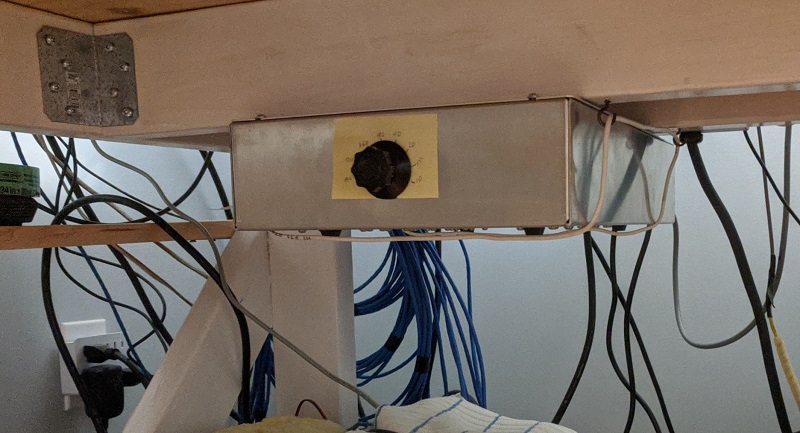
Pavel had not completed design of the control board so I developed my own solution. My simple solution was probably better for me in any case. An 8-position rotary switch is used to manual selection one of the 6 BPF, BPF bypass and automatic band switching via my custom antenna selection software and hardware.
Toroids
There are a lot of toroid coils in these BPF! There are 4 on each BPF for 160 through 15 meters, totalling 20, each with 2 interleaved windings, and double that for two units; solenoid coils are used on 10 meters. I've wound small toroids many times, however it is more difficult to do it well with heavy gauge stiff wire. This chore was probably the most difficult part of the project.

On the left is a toroid built by VA6AM. It's nearly perfect. My first attempt is on the right. That is not so good. Luckily the performance impact of ugly toroid windings is small. Perhaps the biggest risk is excess wire length due to loose winding which increases the inductance. I tried various winding techniques (Pavel made good suggestions) so that my toroids improved over time.

There was no need to go back and redo the earliest ones since they could be adjusted to the required resonance. Indeed, toroid adjustment is, in all cases, done by compressing/expanding windings. It fussy work that is mystifying at first and soon becomes routine.
Construction and tuning
The input and output LC resonant circuits are tuned using a VNA or (less accurately) an antenna analyzer. The objective is to make both equal. A home built VNA probe is shown in use. I found that the 1 kΩ resistor at the end of the VNWA transmit port worked very well. It was suggested by Pavel.
Another common probe is a loosely coupled one turn coil passing through the toroid. It is important not to have the measuring system couple so strongly that circuit resonance is affected.
After each BPF is completed, both ends are connected to the VNA to measure port impedance and insertion loss. For the first BPF I temporarily soldered on BNC connectors (see earlier picture). Using wires is not recommended since they add inductive reactance that will not be present in the final product. The tuning will be incorrect and may be impossible to achieve. These filters are precision devices. The kits come with testing and tuning instructions.

Knowing little about filter design, there were curiosities during the tuning and measurement process. For example, I was convinced that the 40 meter BPF wasn't working properly because the lower band notch was on the high side of the desired pass band on 80 meters. Pavel explained that is expected since for Cauer filters that results in the best rejection across the 3.5 to 3.8 MHz segment typically used in contests. His explanation alleviated my concern, and in use it isn't an issue.

Another was the insertion loss on 15 and 10 meters. It was difficult to get the insertion loss below 0.5 db while also keeping the port SWR close to 1. Pavel tried to explain the reasons but I have to admit I still don't understand.
It was to reduce the insertion loss that he switched to solenoid coils for the 10 meter BPF. He considered using solenoid coils for the 15 meter BPF but that increases the risk of interaction with the 10 meter BPF that also uses solenoid coils.
The complete set of VNA plots can be found below. You can see a glitch on 10 meters for the 15 meter BPF. From additional testing per Pavel's direction it appears to be due to capacitive coupling via the relay boards, possibly between relay contacts and contact wiring. We did a test to ensure that is was not due to direct coupling to the solenoid coils on the 10 meter filter.
Visible in the picture of the 10 meter BPF at right are the back panel connectors and bypass circuit. There are UHF connectors for the input and output, 12 VDC power and a DB9 for automatic switching (not yet wired when the picture was taken).
Pavel noted that the filters are symmetric so the connections can be swapped, however it is not unusual for one permutation to give slightly better performance. In that case it is best to label the connectors as radio and antenna (or amp) and always use them that way. The difference is negligible for my units so I didn't add labels.
Performance
Ordering of the BPF affects performance. 10 meters is closest to the connectors and 160 meters is at the other end of the enclosure. Although the relay board traces mimic a transmission line, they are not perfect and there are the deviations via the relays to consider. The primarily stray inductance is why 10 and 160 meter BPF are placed where they are.
The BPF for the other bands are interspersed so that none is next to that of its second harmonic. For example, don't place 40 and 80 meter BPF next to each other.
Final tuning of every BPF must be done with the full unit assembled in the enclosure and the cover in place. It is also necessary that wiring of the control system (manual or automatic) is complete and functioning.
Another subtlety that affects performance is the soldering of wires from the BPF to the relay PCB. There is a ground connection via the metal stand offs to the enclosure bottom that should not be solely relied upon. One or (better) two short wires should bridge the ground strips at the PCB edges.
The bypass circuit is simple enough, with relays and a short length of RG58. It isn't quite that simple since there is, again, stray inductance. The usual method to alleviate the problem is to place a shunt capacitor at one end of the coax. I experimented and got my best result with a 10 pf capacitor on one unit and (if I recall correctly) 8 pf on the other.

The VNA plots show the difference -- you may have to click on the picture to read the numbers. The scales are different but the marker data tell the story. It is easy to tell which plots are before and after the correction.

The reason this works is that the shunt C and stray series L form an L-network that transforms away the stray inductance. That also changes R but only very slightly for the small amount of compensation required. The same technique is used in wide bandwidth T-bias and other circuits, and I used it to good effect in my stack switches.
The picture shows the shunt capacitor on the bypass circuit (top left). It also shows another on the 15 meter BPF (lower left). I found that I could slightly improve the insertion loss SWR with it. That was possible on 15 meters but not on 10. Since the explanation is a little esoteric and I don't fully understand it, I will say no more.
Pavel was surprised that it worked and understood full well why it cannot be a general solution. It was an accidental yet successful experiment based on my measurements of R and X in this unique case.
I think I've given more than enough detail about how I built and tuned these units, indeed more than most readers want to know! I thought it worth taking the time since the details are quite fascinating to me. Designing filters with such excellent performance is well beyond my ability. All I can do is marvel at what is possible.
If you are in the majority of contesters that use commercial units or a set of high power BPF (VA6AM's are excellent as well), you might now understand more about what goes on "under the hood". Those who haven't read this far, well, I guess you'd rather not know.
The following plots for each band are for one of the units. The plots for the other are almost identical. That's a good indicator that small construction differences have little impact on performance. Careful kit builders should be able to achieve similar performance. As before, click on each picture (there are 3) if they are not readable in your browser.


4 years later
Despite my praise, it has to be said that these devices are not pretty. I could have painted the bare aluminum enclosures, added LED indicators, used a modern knob and added professional looking labels. I didn't see the point since I only touch the units twice in each contest: to switch it to automatic mode at the start back to bypass at the end -- they're in line full time. My preference (as it is for other contesters) is to get them of the operating desk. They are just clutter during contests, even attractive commercial products.
It seems a shame to do this after all the work put into this project. That's how it goes. I also don't need to see patch panels, rotators, antenna switches and all the rest of the station while I'm operating. The desktop looks tidier compared to the last time I showed a picture of it.
Low power BPF are not the highest performance solution to inter-station interference (SO2R, M/2, M/S, M/M). High power BPF are superior. However, that's a much more expensive solution and you can't easily carry them with you to other stations as a guest operator. Harmonic stubs are a good complement to low power BPF to deal with harmonics and spurious emissions from amplifiers. Construction, tuning and placement determine their performance.
Of course you don't need high power BPF if you operate low power or QRP. Low power BPF are sufficient in the majority of cases -- VA6AM low power BPF are good for 100 watts if the SWR is not excessive. I've done QRP contests without any BPF. You just need to avoid frequencies close to the other's station's harmonics.
In closing, I am very happy with these 6-band low power BPF kits. I've been using them for almost 4 years and I am not tempted to upgrade to high power BPF. It's a shame that they are not real products, and may never be. I was the first customer and it is entirely possible that I still have the only ones in active use.
No comments:
Post a Comment
All comments are moderated, and should appear within one day of submission.