The title is the answer to the following question: how do you lift a 300 lb 3-element 40 meter yagi onto a 150' tower?
When we last saw this new antenna it was partially assembled at the launch point for raising onto the tower. A lot of work has gone on since then. There is a great deal of preparation required for a lift of this magnitude go smoothly and safely. I am happy, and relieved, to report that the antenna is on the tower and working. It has already been subjected to high winds and survived the experience.
We need to rewind a few months to understand how I proceeded to design and build the tram line to bring this project to fruition. Don't expect a full blueprint, just enough detail to give you a good idea of how to do it. This is not a project for a novice. Mistakes can be lethal. How?
- If insufficiently strong without supports (e.g. boom truss) the antenna can break, fall and damage the rigging.
- Steel cables under tension will whiplash at high velocity if they kink and break, a mechanical connection fails, or a winch or come-along fails. The cable can maim and kill.
- The tower, mast or ground anchor can fail if improperly engineering or used. Property damage is guaranteed, and life is also at risk. No, you can't run out of the way fast enough and a hardhat won't save you.
- A falling 300 lb antenna striking a guy wire will very likely bring down the tower. See previous bullet.
- A vehicle hauling an antenna up the tram line has sufficient power to break the tram line, haul cable, mast, pulley blocks and mechanical connections if it happens suddenly and power is not removed immediately. See second bullet.
- No matter what you say, crew members (and probably you as well) will remove personal safety equipment and step under the antenna and rigging, usually for no justifiable reason. There is no good reason except under strictly controlled conditions.
- No one should be on the tower during the lift. Leave that until after the antenna is in position and all but the critical cables are slack. If you must be up the tower to facilitate the lift you're doing it wrong.
A professional rigger who loaned several items that I needed for the tram said that for commercial work they strive to use cables, ropes, tools and fasteners at no more than 10% of their breaking strength. This is very conservative since 20% is more typical. When you consider the liability for injuries and property damage for failures of large towers and while lifting heavy loads up those towers the conservatism is well justified. As a ham I am willing to venture higher than 10% but rarely more than 20%. At 30% the alarm bells should be ringing no matter who you are or what you're doing. Don't even think about it.
Amateur radio is a hobby. Be conservative and be safe. There is no shame in admitting a procedure is beyond your ability. Hire professionals.
Do you feel suitably chastened? Sorry to put you through that but it really needs to be said. Repeatedly. In my long experience too many hams have misplaced optimism.
Note on photos: Most of the best photos in this article were taken by Alan VE3KAE. He came over several times to help with antenna and rigging assembly, rigging tests and for the final lift. The worst pictures are by me and my not very good smartphone. I don't show credits on each photo. I also have a new phone that I'll try on upcoming projects.
Taking the time to get it right
I started the rigging in October and the lift was done on December 1. I proceeded carefully, taking all the time I needed to be absolutely certain. I am no novice but this is not a job to be done rashly. We then waited for agreeable weather, and the weather is rarely cooperative this time of year.
I cancelled the first scheduled lift day because I wasn't fully satisfied with the rigging. That was easily remedied but a week passed before acceptable weather returned. There was also snow on the ground.
The setup
A lot of space is needed for the
big tram. The diagram below has been supplemented with an aerial
view (overlaid on a Google satellite image) and photos of critical
components.

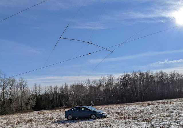
The tram line anchor on the ground is a large tree wrapped with chain. The upper end of the tram line is halfway up the 10' mast and is comprised of several commercial rounded mast plates. Due to the required force to withstand the weight of the antenna and tram line and the tension of the tram line and haul cable there is a back stay. The back stay is essentially a temporary guy. I was lucky to find a suitable tree (large and healthy) that is ~1° off a direct line through the tower. The mast pulley is placed on the other side of the mast to compensate, but that wasn't really necessary.
The haul cable is 500' long to traverse the large distance from the launch point, over the tower to the guy anchor and then horizontally to the vehicle. My preference was to have the haul cable run straight down the tower, as I've done many times before. That required a cantilever and second pulley that would be under high stress. Taking the cable outward from the tower is easier but adds complication during the lift, as we'll see later.
The overall procedure is to crank the winch to lift the antenna far enough that when the haul cable is pulled tight the rear tips of the long elements don't strike the ground. The back stay is tightened to keep the mast vertical. The antenna is hauled up until the forward tips approach the forward guys. The tram line is again tightened and the tag line pulled to tip the element to be more vertical. When the antenna reaches the tower the tram line and back stay are slacked so that the boom rests against the mast plate. We climb the tower and bolt everything together.
There are two lifts. The first is the antenna without the driven element. That reduces the weight to less around 250 lb, which includes the rigging. It also prevents severe interference between the driven element and its fragile capacitance hats, the cables parallel to it, the tower and mast, and the 10 meter yagi at the top of the mast. The driven element is lifted end first, just as it was for the dipole that was lifted last year, and taken down the same way earlier this fall.
That's the summary. Details follow.
Equipment choices
EHS 7×1 guy strand is not ideal tram line material because of the bend radius imposed on it by the antenna weight pulling on the tram line pulley blocks. However it is strong and I have a lot of it scavenged from commercial towers. The tram line and the tram line extension to the anchor is ¼" EHS. The extension is needed since the longest length in my stock is 200'. It is the same cable used a year ago to tram the 5-element 20 meter yagi to the top of the 140' tower.
The breaking strength of ¼" EHS is 6000 lb. Tension during the procedure never exceeded 800 lb, or 13% of breaking strength. The winch is rated for a 1750 lb working load and its cable is ⅛" aircraft cable with a breaking strength of 2000 lb. A come-along was used on the tram line when the tension exceeded 400 lb (20% of breaking strength). Shackles, chains and other cables in the rigging are used within their working load limits.

The haul cable is 500' of 7×19 3/16" aircraft cable with a breaking strength of over 4000 lb. A smaller cable could have been used since the weight it would have to support is no more than 250 lb. I followed the advice of the professional to buy the bigger cable as a safety margin, both for the lift and in case there was tangling with the rest of the rigging.
Rigging the antenna
For the initial test of the rigging the connections to the antenna were partially improvised. I used materials that are easy to work with but that are not of adequate strength for the lift. Once we were satisfied with the overall setup, stronger materials were substituted.
With the first version of the rigging the antenna was lifted by the winch. The element tips and capacitance hats were not attached to protect them during the trials. As the tram line is tightened the antenna moves backward and can spear the element tips into the ground. The tips, though tough enough on their own, cannot withstand the weight of the antenna bearing on them. I had a friend (Alan VE3KAE, seen below) help with the test of the rigging.

Notice the bowing of the boom. The boom must support its own weight of 110 lbs and 45 lb of element and clamps at each end. The boom can withstand the static stress. It is important to install the boom truss as soon as possible after it is on the mast since the boom isn't likely to survive a high wind without it. On its own, it can handle the weight or the wind load, but probably not both.
The antenna is unbalanced in this test. The reflector (nearest element) is heavier than the director by about 3.5 lb, and about 4 lb with the tips installed. Finding the centre of gravity (CoG) by experiment alone is tedious so I developed a spreadsheet to calculate the moment on each side of the tram line. When the antenna was assembled and the exact CoG found, the calculation was off by just 1". Balance helps to steer the element tips clear of the top guys and the 10 meter yagi atop the mast. The 10 meter yagi is 24' long, which is only half the boom length of the 40 meter yagi, so the reflector and director clear the 10 meter antenna with room to spare.
Below is the final rigging of the boom. It is worth describing a few details.

The are two ¼" commercial steel plates to secure the rigging to the boom. One chain attaches to the tram riding trolley and the other to the haul cable. The chain for hauling is shackled to the plates. When the cable is pulled the plates align with the tram line and that tips the elements up. The trolley is ½" steel plate with shackles to hold the pulley blocks that ride the tram line.
Although small, the pulley blocks are rated for a few tons of working load. I used two to spread the load on the EHS, to reduce deflection and point stresses that can damage the cable. After the rigging was dismantled I found a couple of small kinks near the bottom of the tram line, where the trolley was positioned most of its time the antenna was off the ground.
The truss cables and turnbuckles are tied together and to the boom plates, and held to the boom with cable ties. It is important that they don't escape or the antenna would probably have to be lowered to retrieve them. After it is raised the extra rope length is looped over the tram line to keep the truss half tied together and free to reach the mast clamp.
The light duty steel angle and attached tag line are used to tip the elements further upward to clear the top guys. After the boom is bolted to the mast plate the angle stock is a lever to rotate the boom and level the elements. The alternative is to wait for the driven element and use that as a lever.
The lift
The tricky parts of the lift are the beginning and the end. Watching the huge antenna slide up the tram line is awesome but requires no work other than keeping in communication with the driver. The first step is to lift the antenna by pulling in the slack in the tram line. During this process the tension rises only slowly. We stop when the winch is too difficult to turn or the tension reaches 400 lb. There is a Loos tension gauge on the ¼" EHS tram line extension cable. The come-along is attached to the extension cable with a sacrificial pre-form and the tightening continues.

What we're really doing is raising the antenna rather than increasing tram line tension. That is because the antenna is so far along the tram line. The loading is very different when the launch point is closer to the ground anchor and when the antenna approaches the top of the tower. It was interesting to watch the tension gauge hold steady as the tram line is tightened. That isn't what most people expect to occur.
Once the antenna is a few meters off the ground the car rolls forward a foot or two to take the weight of the antenna. One person watches each rear element tip to keep them from spearing the ground. When it's high enough we spread the capacitance hats.

I confirmed in the model that the hat arms don't have to be at exact right angles to accurately reproduce the loading effect measured last year. We did it anyway since it looks prettier that way. Helping me out (above) are fellow contesters Vlad VE3JM (left) and Greg VE3PJ (right).
We did have an accident when one of the arms broke. I believe it was the arm that snagged and bent when it was lowered from the tower earlier this fall. An hour was spent building a new one. Before resuming we stopped for lunch. The antenna was left hovering above the ground.
John VE3NJ is driving his car in reverse to haul the antenna because the tow hooks are at the front of the chassis. The car may seem small for the job but it is in fact perfect. The peak towing load is only slightly more than the antenna weight and that is only reached when the antenna nears the top of the tram line. The engine's moderate torque capacity gives the driver an excellent "feel" for the load and mechanical snags that might occur.
The automatic transmission is particularly helpful to control torque and avoid sharp acceleration and deceleration. My car has a manual transmission which makes torque control difficult. I salute John for his willingness to drive into the snow filled hay field.
The unevenness of the hay field caused some difficulty. Two of us had to push the car when it entered a small depression and the drive wheels spun in the deeper snow.

The tension on the tram line drops to a low value as the antenna approaches the top of the tram line. That can come as a surprise. The weight of the antenna at this point is almost entirely on the haul cable, so the tram line carries less of it.
The partially slack tram line must be tightened at this time to raise the antenna to help it clear the top guys and the prop pitch motor platform (it's the blob just below the top guy station). Turning the winch crank quickly raises the tension, so we again switched to using the come-along on the heavier EHS. A guy grip locks the tram line to the chain around the anchor tree. The back stay must be adjusted to compensate for the increased lateral force on the mast.
I put most of my weight on the tag line to raise the forward tips well over the top guys, while at the same time shouting instructions at John (with others relaying my words through the car window). We all had radios but without VOX I can't transmit when both hands are occupied.
The boom briefly tapped the top guys and then cleared the prop pitch motor. The boom bumped into the top few inches of the tower but in a moment it was over the top. We slacked the tram line and back stay so that the boom hung straight down at the level of the mast plate.
The top safety rope now comes into play. Look at the top diagram to visualize the forces at play. With the tram line and back stay tension eased, we are left with the lateral force of the haul cable due to the ground pulley being 120' from the tower base. The safety line is there in case the mast bends backward more than I'd like. It turns out that it wasn't so bad and the safety line may have been unnecessary. Knowing what might happen is why I took this precaution. The inset photo (diagram above) shows the mast rigging after the safety rope was moved out of the way of the truss clamp.
Securing the antenna
I climbed the tower with the 4 u-bolts to attach the boom to the mast plate. It was remarkable that I had to instruct John to lower the antenna only 1" to align the boom with plate holes. They went in with no drama at all. The antenna was secure at the top of the 150' tower. The car moved forward to fully slack the haul cable.

The chains from the tram line trolley and haul cable were removed and the tag line transferred to the trolley. I sent the lot of down the tram line. With the tram line slack, the dangling chains strike the ground to slow it down and prevent damage.
Free of the pull of the trolley and haul cable, the boom was rotated with the lever. The elements couldn't be completely levelled until later when the rigging plates on the boom were removed. That was done after the boom truss was connected to the mast.
The position of the rigging plates up the mast made it difficult for one person to attach the boom truss cable to the mast clamp. Vlad VE3JM joined me on the tower to lend a hand. One of us pulled in the truss cable and the other drove the bolt through the clamp and turnbuckle eyelet. We then levelled the elements. By tightening the turnbuckles we levelled the boom.
The sun was setting so that was it for the day. We took pictures, climbed down and my friends left for home after a very productive day.

These are the pictures Vlad and I took of each other, and one that Alan VE3KAE took of us from the ground. They make a pretty mosaic.
Driven element
The weather worsened so we could not raise the driven element for two weeks. During that time we had two wind storms, one of which hit on Dec 11 with gusts of 100 kph and higher. My imagination did run a little wild since it was nighttime and I all I could do was listen to the wind roar for several long hours. In the morning light I was relieved to see that the antenna and tower were unharmed. The tower and antenna are designed for survival, but that never completely allays one's fears.
Wind on the scheduled day was gusting to 50 kph on the ground and higher on the tower. We went ahead because there was a problem finding a day with better weather when I could gather enough helpers. Good tower work weather is uncommon this time of year. For this last step we were the same group as before, less one person.

The wind was really strong so we had to alter the rigging to lift the driven element safely. It is going up end first and by muscle power using the same tram line. The steel haul cable was replaced by rope since it is far easier to work by hand. It went up end first to thread the triangular gap between the boom, mast and boom truss. The leading capacitance hats are only unfurled once they're through the gap. That was my job.

The element was whipping around so much that I tied the haul rope to the leading edge of the element 1" tube just inboard of the capacitance hats. With that simple addition the tip pointed straight ahead and parallel to the tram line. The tip points at the mast where the tram line anchor and haul pulley are mounted. I removed the wire and gently pushed the capacitance hat arms around the mast.
There were tense minutes after I saw that the capacitance hats were above the tram line and a fix was required. At some point near the ground, when the element was swinging in the wind it someone twisted up and ended up on the wrong side of the tram line without any of us noticing.
Choreographing a few acrobatics with the capacitance hats I was able to get them back under the tram. Hauling continued until the element-to-boom clamp was on the boom. Getting that 60'+ element steady enough in the gusting wind to thread the u-bolts was a challenge.
With the element bolted down I loosened the boom and used the driven element as a lever to better level all of the elements. I couldn't yet slide the DE into its correct position because the slack tram line was lying across it. It was getting late so we called it a day. The sun set early this time of year.
The next day I dropped the tram line on my own and slid the DE to its position on the boom. I then did the first test of the SWR, using a variable capacitor in place of the capacitor inside the gamma rod. The measurement after adjusting the capacitor indicated that the antenna was behaving as a yagi, but with a couple of surprises.
More on adjustment and getting the antenna on the air in a future article. The weather this week has been continuing warm, if wet and windy at times. I have to move quickly to beat the weather. The rigging is now been completely removed from the tower, and work on the yagi feed is ongoing. Whether it works or not the antenna is going nowhere until warm weather returns.
I'm pushing it to the deadline but this antenna will be working and on the air this year and before the serious winter weather rolls in. This is the pinnacle moment of my 2021 station plan and I intend to get it done right and on time. I let other items slide but not this one.

While the work was going on we were so wrapped up in the details of getting it done that it was easy to forget how big this thing is. It is no surprise that very few hams have a 40 meter yagi with 3 or more elements. It was a shock to look out the window the morning following the big lift and see that monster perched at 150'. It's impressive and intimidating. However, an antenna is meant to be used and not merely admired as an ornament.
I hope that this story about large antenna tram lines has been of interest. Not many would choose to raise an antenna of this size without hiring a crane.
Hi Ron ! Amazing antenna farm ! glad to meet you on 20mt tonight ! HPE CUAGN best 73 de Mario IK1LBL
ReplyDelete