Instead I'll focus on a narrower topic in this article: customizing guying hardware for my new 140' guyed tower. When you buy a used and obsolete commercial tower and you want to be economical (that is, cheap) there may be components to be fabricated or improvised. Whether original or replacement, all components must be up to the demanding loads such a tower will be subjected to.
My choices are not necessarily the choices others would make. That isn't important. What does matters is to design and build components that are up to the demanding requirements. Many choose to overcompensate with excessively heavy, strong and expensive solutions. Having some understanding of what is going on can lead to more moderate solutions. That is my approach.
Anchor rods
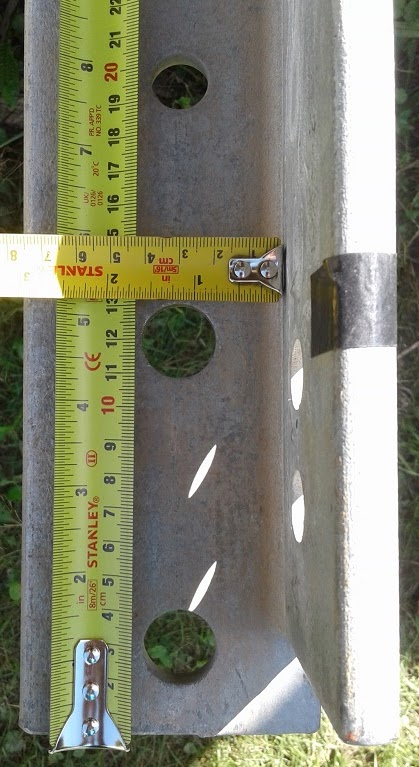 Wandering through my local tower company's stock of surplus parts several lengths of steel that made good anchor rods were spotted. These are galvanized angle stock 10'-6" long and ½" thick. There are pre-drilled holes suitable for attachments top and bottom. The larger ⅞" holes are the ones I used.
Although I neglected to take a picture of the completed anchor rods bottom end what I did is easy to describe. Approximately 3' lengths of ⅞" steel rod (which I got as part of the deal) were inserted through those holes. These are the load bearing members that couple to the reinforced concrete anchors previously shown.
I used two rods to double the load bearing surface. Using the bottom hole alone is a poor choice due to the small amount of steel between the hole and edge; guy tension pulls towards the top of the picture which puts the load on the bottom of the holes.
A typical commercial anchor rod for this application is 1" round galvanized stock. Since strength is largely in proportion to the cross-sectional area of the rod ½" angle stock of this size works well, and can be stronger if correctly adapted. I have seen ham towers with two ¼" angles back-to-back, which is roughly equivalent. One difference between round and angle stock is that the round stock behaves more predictably if the rod is not installed at the correct angle, both lateral and vertical. So if you do use angle stock, which is usually less costly, oversize angles are not a bad idea.
Guy attachment plates
Commercial anchor rods have at least a closed eye at the upper end for attachment of guying hardware. Mine have a few holes that I put to use. Those holes are symmetric with those on the bottom end. It was up to me to come up with a suitable attachment plate.
What I do have is the original L & R equalizer plates for this tower. There are 5 holes for ½" turnbuckles with U terminations (similar to shackle pins) and one large 1" hole for attachment to the anchor rod. My challenge was to design a simple and effective method of coupling the equalizer plate to the angle stock. The alternative is to weld the back of the plate to one edge of the angle, similar to what I did for the existing LR20 tower.
First, it helps to get a little bit lucky. I was able to find ½" galvanized plates of the perfect size in those aforementioned surplus bins. Again, the price was unbeatable. All I had to do was machine them to fit. That is, once I calculated the required load capacity. Let's start with a brief discussion about shear.

The diagram comes from a Fastenal technical reference on a variety of load applications for structural fasteners. I highly recommend it. It shows the correct way (on the right) to use a bolt to link three plates under double shear load. You can imagine that the upward load is the equalizer plate (with the guys) and the lower loads the previously mentioned use of two linked angles as an anchor rod. Notice the importance of ensuring the load bears on the unthreaded surface of the fastener.
 In my case there is only one angle. Coupling them in the simplest fashion is a case of single shear, which places a large shear load on the bolt shank, head and nut. This can be done but is not ideal. Double shear keeps the full load on the shank, leaving the bolt head and nut to merely keep the plates in position. You'll see an application of single shear in the next section, and the fastener requirements.
The existing ⅝" holes in the link plates were widened to ¾" to accommodate the calculated diameter of grade 5 bolt to comfortably exceed the load requirement. The unthreaded section of bolt under the head is 1-½", perfect for 3 × ½" plates (the equalizer plate is ½").
For the calculation I assumed a peak load of 3× the pre-load of 1100 lb on 4 guys (30% of 5/16" EHS guy strand breaking strength). The Fastenal technical reference provides excellent information about the strengths of various fastener types and grades. Indeed it provides far more detail than most of us would ever want to know.
To confirm my calculation I asked a friend with an almost identical tower what he uses. He has the same size ¾" grade 5 bolt. Although he opted for an A325 bolt, which is not really necessary for double shear applications.
During construction the upper bolt is not fully tightened to allow the equalizer plate to freely rotate. It will be snugged up a little when I'm done to ensure the three plates cannot twist.
Notice that I used holes on the link plates and the anchor rod far enough back from the ends to ensure the maximum amount of steel surrounding the stress points. This left barely enough room to fit the turnbuckle pins.
Tower guy yokes
The tower came with only two sets of the original LR20 guy yokes. I need four sets. The guy yokes are unique items that, like the tower, have been out of production for at least 20 years. In the photo below I show one set that I used to temporarily guy the bottom section until the first permanent guy station at 30' was reached.

The are made of ½" hardened steel with 9/16" raised threaded ends for extra large bolts that prevent pull out from the purpose-made holes in all tower girts. The girts are designed for this purpose. I add washers under the nuts to reduce the potential for stress risers and bending of the girt steel, which is not uncommon with LR20 towers.
The yoke design is a good fit for guy termination thimbles. The method of tower attachment allows the yoke to pivot to accommodate the wide range of angles across all guy levels. Because the steel is so hard it takes a bit of muscle to hold apart the arms of the yoke for insertion into and removal from the girt.

The custom yokes I designed and had made in a machine shop are shown above. This was the second attempt after the ¼" galvanized plates I provided to the machinist were bent at a greater angle due to miscommunication. He made new ones from ⅜" plates, which I painted since they are not galvanized. Machining was completed in my workshop once I decided on how to attach the guys.

The greater bearing surface is needed to withstand the shear force between the tower girt and yoke plate. Again I refer to that Fastenal document for a diagram demonstrating such single shear loading. The bolt head and nut experience stress risers and the shank has bending stress. A325 bolts and nuts reduce that stress. The stress is further minimized by keeping the plates -- tower girt and yoke plate, in my case -- tightly bound by approaching the maximum torque.
Another A325 bolt binds the yoke plates. Without it the guy tension would gradually bend the plates and allow them to tilt downward, both actions will weaken the plates and reduce guy tension. You should also notice that the original bolt (left) isn't long enough to allow the nut to fully thread onto the bolt. This was corrected (right) before the guys were pulled tight. When the picture was taken there was 700 lb tension on the guy.
I could have used shackles to connect the guy thimble to the yoke, but I don't have enough of the appropriate size. The shackles I planned to use have a pin opening of ½", which is not enough to accommodate back-to-back ⅜" plates. They would have fit the original set of ¼" plates. Instead I drilled the holes out to ¾" to fit a heavy duty thimble and guy grip.
The custom guy yokes are used at the lower two guy levels -- 30' and 65' -- where the guy angle is closest to horizontal. Considering that these yokes cannot pivot this is the best place for them.
Bearing plate
The tower bearing plate is indirectly related to guying. Its function is to transfer the vertical tower load onto the base pillar without creating point stresses while allowing the tower freedom of movement (rotation and tilt). The force involved is substantial, of which the largest portion is due to the combined vertical component of the total guy force vector. The tower itself weighs less than 2000 lb (0.9 tonnes) yet the vertical force can exceed 10,000 lb (4.5 tonnes) under severe wind load.

The opening in the base section is 1-⅝". The pier pin is ~1.3"; it doesn't have to be a precision fit. The bearing plate is a surplus ½" galvanized steel plate that was pierced in a machine shop to slide over the pier pin. The plate is approximately 7" × 7".
The dimensions of the bearing plate are not critical; L & R recommended 8" × 8". For the design load the ½" thickness is close to the minimum size. Thinner plates will curl over time, reducing the effective contact area. A plate wider than the 12" diameter of the vertical rebar cage is not well utilized. Over the years there will be some grinding of the plate due to the rotational load of the yagis. This is preferable to rigidly attaching the tower to the base.
The bearing plate is grouted to the pillar to improve mechanical coupling and to ensure the plate is level. It is difficult to perfectly level the concrete pillar when the concrete is poured and wet. Downward pressure is placed on the plate while the grout is partially. The plate is adjusted with a level. Excess grout is scraped off the sides of the bearing plate.
Corrosion
You'll have noticed my emphasis on using galvanized steel and fasteners for all components. Corrosion protection at these critical points is mandatory. Rust weakens the tower and replacement of corroded parts will eventually be necessary. This can be done but it is not easy.
Where I wasn't able to use galvanized steel the parts are painted with good quality steel paint or with cold galvanizing compound. I do the same with old turnbuckles. Even the tower itself which is hot dip galvanized and painted was cleaned and given a fresh coat of paint, using a compatible primer over bare galvanizing where the paint has worn off.
Anchor rods of any type must be galvanized or use another ground-rated coating because corrosion due to soil chemistry can severely shorten its lifetime. It is a good idea to dig down a foot every couple of years to check the rod's condition.
I'll close with a picture of the tower raised to 70', using all the custom guy hardware described in this article. As one might say about winter tower work: sure it's cold, but there are no bugs!

No comments:
Post a Comment
All comments are moderated, and should appear within one day of submission.