 The yagi modelled in this article is easier to build since it uses inverted vee elements. It requires only one support -- for the boom. The ends of the antenna are tied to ground supports with the aid of ropes from the element ends to the tie point.
The model is identical to dipole array save for the bending of the elements at their centres. I set the interior angle to 120° and left the element centres at the original height of 20 meters over a medium ground.
Symmetry (as I harped on before) remains critical to array performance. The angles of the elements should be equal -- this is more important than adhering exactly to an angle of 120° -- and remain parallel to each other and orthogonal to the boom. This requires some care in the selection of tie points. It is also important to use high-quality end insulators for the elements, and not simply bind the rope directly to the wire ends. What may be acceptable in a single-element antenna can destroy the performance of an array.
The design itself is quite simple. First I took the (EZNEC modelled) reference dipole from that previous article and bent it into an inverted vee with an interior angle of 120°. The SWR was then swept to find the resonant frequency. Bending the elements in this manner raises the frequency at which the antenna reactance is 0.
The resonant frequency rose by 1.27%. For small percentage changes (under 10%) it is sufficient to simply change the antenna length by the same amount. In this case the legs of the vee were increased by ~1.27% (rounded to the nearest centimeter) which moved the resonant frequency back to where it was for the original dipole.
The purpose of doing this was to avoid a lengthy retuning procedure for the yagi which is complicated by the 3 meters of ladder line running from the switch box to each element. Using an educated guess as to the impact of the fixed ladder line length's on the total element resonance I proceeded to add 1% to each element leg before bending them into inverted vees. Scaling elements in EZNEC is something I prefer to avoid since it can be tricky, or at least finicky.
Here is the SWR sweep that I got from this simple procedure.

If you refer back to the earlier article you'll see that the SWR curve is almost identical. What can I say except that I made a lucky guess.

A match is nice but insufficient. We need to look at the yagi's performance. The questions to be answered are: are the frequencies of maximum gain and F/B in the correct positions, and, how does performance compare to the yagi made from dipole elements?
To make the comparison easy I put the performance plots for the dipole yagi (from the previous article) and the inverted vee yagi next to each other. It should be obvious that the two are very similar, with some important differences.
Please note that all gain and F/B figures are, again, at a 10° elevation angle, not at the angle of maximum radiation. I chose this angle because it is a good median value for DX paths.
- Despite the same SWR curve the frequencies of maximum gain and F/B are both lower by about 25 kHz.
- The F/B curve, apart from the frequency shift, is nearly identical.
- The maximum gain is lower by about -1 db. This is expected. However the gain bandwidth is sharper; gain falls off more quickly at higher frequencies. At 7.2 MHz, for example, the gain is -1.4 db versus the dipole wire yagi. This may be difficult to discern in the chart.
- The gain versus the reference inverted vee is comparable to the gain of the dipole yagi versus the reference dipole. The reference inverted vee is approximately -1.6 db versus the reference dipole.
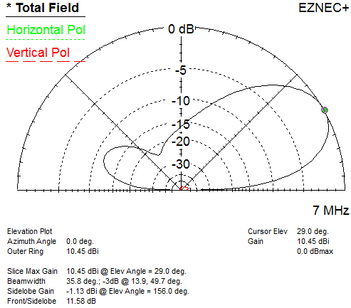 Of course the height of average current is responsible for gain differences at low angles. The elevation angle of maximum gains of the reference dipole and inverted vee at 20 meters apex height are 30° and 32°, respectively. However for the dipole yagi and inverted vee yagi these angles are 28° and 29°, respectively.
The yagi gets its gain by narrowing the main lobe in both azimuth and elevation. Thus a yagi at the same height as a dipole concentrates more of its energy at lower angles. This improves DX (low angle) performance versus non-DX QRM (high angles) in the direction the beam is pointing.
My final act with this model was an attempt to raise the frequencies of maximum gain and F/B back to where I wanted them (the same as the dipole yagi). Although the impact of the 25 kHz lowering of these frequencies is not a serious flaw I am interested in how difficult the tuning would be. I tuned these parameters by shortening the length of the reflector stub by 6 cm, from 1.12 to 1.06 meters.
Unfortunately this changed the (above) ideal SWR curve by shifting the minimum SWR point higher by 20 kHz. The tuning of the reflector changes the array resonance in the same direction. Although minor the SWR at the bottom of the band rose to 2.1, which may be a problem with some transmitters. By adjusting the length of the beta match stub I could shift the resonance almost to where it was before. However, this simple act did not change the SWR at 7.0 MHz.
A full tuning procedure would be require per the step described in the previous article. Since this is not an antenna I plan to build I decided to stop and sidestep the additional work. I have one more variation to apply to this antenna to make it something I would be willing to build. That antenna may be worth the effort of detailed tuning. This will have to wait for future article when I have time to do the modelling work.
Lots of information on tuning a low inverted v dipole, but no info on beam spacing.
ReplyDeleteIt's implicit rather than explicit. In the 1st paragraph is a link to a previous article, and there is a note saying that other than turning the elements from horizontal to inverted vee the physical dimensions are the same.
Delete73 VE3VN
ok now i see thanks
ReplyDelete