The focus on gain and overall performance in my survey hides an ugly truth behind all the variations and subtleties of these yagis: height can be a more potent factor than gain. Now is the time to look again at all these antennas and see how they stack up (pun intended) when compared at various heights. The heights I'll investigate are greater than in my earlier survey of wire antennas and arrays in order to firmly establish the study in the context of that big tower.
Although the majority of readers will never have a tower or antenna of the sizes I'm looking at there are lessons for everyone. So read on no matter your ambitions for 40 meters.
Antennas in the survey
I selected antennas both as references and as representatives of one or more yagis in a performance class. The metric gain, and nothing else. Not just gain but gain in free space. Where the antenna shows significant gain variation with frequency I chose a frequency that has the gain reference point I used to chart its performance. This is most applicable to 2-element yagis of all types, and typically less so as the number of elements increases.
With that done I placed each antenna at 10 meters height (apex height in the case of inverted vees) over EZNEC medium ground. The gain at 10 elevation is measured and plotted. This is repeated every 2 meters height up to 40 meters, which is approximately the height I am targetting for a rotatable yagi.
Here are the antenna I used, along with the free space gain at the reference frequency. Links to earlier articles are inserted where applicable.
- Inverted vee with an angle of 90° between the legs (1.5 dbi). This is my choice for a base reference since it is the simplest antenna to mount on a tower.
- Dipole shortened with a small capacity hat and coil, similar to the driven element of the Cushcraft XM240 2-element yagi (2 dbi). The model overstates the gain by approximately 0.3 db so you may want to subtract that amount when looking at the charts.
- 2-element switchable inverted vee yagi with an angle of 120° between the legs (5 dbi). Since it is not rotatable it is included as a second reference.
- 2-element shortened yagi, such as the Cushcraft XM240 or W6NL Moxon (6 dbi).
- 3-element yagi shortened with loading coils and optimized for gain (7.5 dbi). A comparable commercial product is the M² 40M4DDLL
- 3-element full-sized yagi (9 dbi). Many hams build their own since the several available commercial products are very expensive and difficult to ship.
- 5-element switchable inverted vee yagi with an angle of 120° between the legs (10.5 dbi). I chose this as an upper-bound reference since it is the simplest antenna that exceeds the gain of a full-size 3-element yagi.

Not explicitly listed is a hybrid wire and tubing antenna from ON4UN's Low-Band DXing book. This is a design by NW3Z that resembles a Spiderbeam. The text claims a modelled gain of better than 7 dbi, but I was unable to achieve that in a NEC2 model despite care in construction of the model. I experimented with a few variations to boost gain. The best I achieved was 7 dbi and that took a physical design that is more fragile than that in the book. The model view of the antenna is adjacent. It appears it comparable to the XM240 or W6NL with respect to gain, F/B and SWR. That is, no better than a 2-element yagi.
Elevation angle
As in the past I will continue to use 10° as the target elevation angle for 40 meters (for example, see the ARRL Antenna Book) since it is the median for inter-continental DX paths, such as between VE3 and Europe. Longer paths have a lower median angle, sometimes as low as 1°. Although the gain figures will be lower at these angles the comparisons remain valid since all horizontal antennas behave similarly as the elevation angle approaches 0°.
Height vs. gain
First the chart with the modelling results and then my analysis of what it can tell us.

 Notice how the gain of the yagis largely track each other with a change in height. There is more spread with two single element antennas: the inverted vee and short, rotatable dipole. In the latter case the near isotropic pattern in the vertical plane interacts more strongly with ground resulting in larger high angle lobes at certain heights which "steals" from the power in the main, low angle lobe.
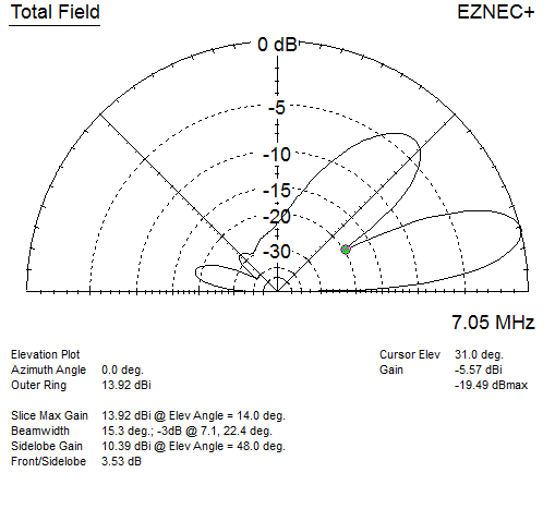
The narrower main lobe of the yagis is more immune to this effect but it is still present for yagis with a low element count. The pattern shown at right is of the 3-element full size yagi at 40 meters height.
No matter the element count all the antennas with inverted vee elements suffer a sharper drop in gain as low heights. This is due to the lower average height of antenna current in the sloping legs. At 10 meters apex height the bottoms of the inverted vee elements are only 2.5 meters above the ground.
Nulls and domestic coverage
In the above pattern I marked the angle of the first and only major null. The null at 31° is significant. It reduces gain by -5db or more for elevation angles from 25° to 42°. That's a problem even if you are only interested in DX. For contests it's worse since the antenna will perform poorly for much of the US from my location (or within Europe for Europeans).
The null angle rises as the antenna height is lowered. That is why big contest stations either use a switchable stack on 40 meters or have at least one yagi at a lower height. This also allows for diversity by, for example, pointed the high yagi to Europe and the low one southwest through the US heartland. Unfortunately a height of 40 meters is not high enough to achieve good stacking gain with a large yagi for this band. The upper yagi ought to be at least 50 meters high and preferably 60 meters. This is extreme and well beyond my ambition. If you've ever visited a station with one of these stacks they are certainly impressive sights! If you do want at these heights you are better off using 2-element 40 meter yagis.
If the yagi is no more than 30 meters high it is possible to successfully cover both short and long paths with the one antenna. You need only be prepared to turn it a lot throughout the evening during contests. If you do go higher such as I intend it is necessary to have a low antenna as well. This could be as simple as a fixed dipole or inverted vee up 20 to 30 meters.
Note that for the inverted vee antennas, including the switchable yagis, the null angle will be higher by a few degrees. In the case of a 40 meter height the null is at 33°.
Diminishing returns, and a little calculus
As you go higher the main lobe points to a lower elevation angle. This is what we usually need for effective DX communication. Unfortunately the amount of additional gain we get for each height increment is not constant. There comes a point of diminishing returns. Where we draw that point is one of personal choice and circumstances. That is, for those who have the option to go higher.
I took the data for the previous chart and took its derivative. If you don't know calculus this is simply a rate-of-change calculation whereby we determine the rate of gain change for a change in height, for every height for every antenna is this survey. In calculus terms this can be written dG/dH. We'll be doing a discrete calculation, not develop a continuous function, since this is easier done and sufficient for our purposes. That is, numerical differentiation.
I did this by taking the gain at adjacent heights, which are at 2 meter intervals, taking the difference and dividing by 2. This is trivially accomplished with any spreadsheet software. Here is the result:

As before the rate of change for the inverted vee antennas is large at low heights. Single element antenna are more variable since their free space pattern is close to isotropic in the vertical plane, which allows development of a strong upward lobe at heights that are an odd multiple of λ/4. The effect on yagis is subdued because their free space patterns have diminished gain directly upward and downward.
In my earlier height vs. gain article I stated that dG/dH ≈ 0.6 db/m for heights between 10 and 25 meters. While roughly correct the truth is more complicated. We can see that for yagis dG/dH is already below 0.4 db/m at 25 meters height. Going higher we see that dG/dH levels off just below 0.2 db/m.
This is useful information. If you are planning a 30 meter tower with an M² 40M4DDLL and you decide to pursue 1 db more gain you have two kinds of choices. One is to increase tower height to 35 meters. The other is to put a full-size 3-element yagi on the 30 meter tower. Actually you'll get 1.5 db additional gain in the latter case, and the first null is more compatible with domestic length paths. A third option of stacking smaller yagis can also work but will do little to improve low angle performance at this height.
If instead you want to choose between the 40M4DDLL and XM240 at 30 meters height you need to go 6 or 7 meters higher to compensate for the lower gain of the XM240. Since the gain bandwidth of the smaller yagi is narrow you should really aim for at least 10 more meters. These are good questions to ponder when building an antenna farm even if your antenna objectives are modest, such as a more typical tower height of 15 to 25 meters.
Terrain
Choosing an antenna and a height for it is not so simple as presented above. Terrain plays an important role. Modelling software treats the earth as an infinite flat plane of constant composition. While this allows consistency in antenna modelling it can severely misrepresent the true far-field pattern.
Serious planning benefits from terrain analysis. I have little to say about this other than to direct readers to tools such as HFTA. When combined with high-resolution topography data it is possible to achieve reasonable accuracy in the real far-field pattern for yagis at various heights and azimuth directions.
In my case I am unlikely to purchase a site based on HFTA. At best it will be of interest only after the fact. By choosing criteria for property that avoids certain negative attributes I expect to not have major difficulties. These criteria include avoiding valleys, bumpy and rocky terrain and the urban jungle. There are no mountains here that need to be avoided. Choosing a home and neighbourhood is not only about radio, unless it is only to be used during contests and not for daily living.
Terrain may be a greater factor when encountering the real world, yet when a location is selected the analysis will add colour to the terrain effects. Nevertheless the analysis in this article does provide useful insights into the benefits and risks of combinations of height and antenna type.
What to do about that tower
In light of the diminishing returns of height and its impact on DX vs. North American coverage it is reasonable to ask whether a tower of of 40 or more meters height is a good investment. A lower height would surely reduce cost, worry and maintenance without sacrificing much performance. So why go this high?
For non-competition operating a few extra decibels of antenna performance is difficult to justify. Some hams do it anyway if only because of the challenge or for the bragging rights. But few people are impressed by braggarts. Even for DXers the advantages are questionable. It may only come down to working that elusive P5 DXpeditions an hour later than you could with the maximum investment. Perhaps a larger, legal amplifier is all you need.
Contests are different. An additional decibel or two pays dividends. The band will open earlier and close later, and you'll reach the many modest-sized stations with greater consistency. If doing well in contests is your ambition it can be very worthwhile to take on the time and expense.
With respect to antenna choice there is something to be said for large wire yagis such as the 4 and 5-element inverted vee yagis presented. Since the bulk of contest QSOs are to be had from a small range of directions a fixed antenna is worth consideration, if combined with a more modest rotatable yagi. However such an antenna requires two tall towers, which will put these antennas out of reach for many. There is also an increased risk of antenna interactions, and thus on multi-op and SO2R operations.
We must keep in mind the matter of bandwidth. Only 2 elements on 40 meters is insufficient for optimum gain, F/B and SWR at more than a segment of the 40 meter band. A low SWR and F/B can be had with a Moxon style yagi such as that by W6NL, but it will not improve gain. Some may be satisfied with this compromise.
I will continue to mull it over. First I need to purchase the property and explore alternative tower and antenna combinations that fit the property. The first year I can make do with XM240 before deciding on a larger antenna. Readers can use the presented analysis to assist making their own choices to fit their circumstances.
No comments:
Post a Comment
All comments are moderated, and should appear within one day of submission.