Thursday, May 26, 2022

50 Years a Ham

In the previous article I mentioned that I attended the Contest Dinner at the Hamvention last week. One of the things they do is to find the ham that has been licensed the longest. If you've been a ham 25 years you stand up. As the years are incremented more and more hams sit down. When it came to 50 years, I didn't sit down.

It's a little scary to think about: 50 years. I was licensed in 1972 at the age of 15. The certificate was issued on May 24. I suppose it was technically wrong to keep standing since I was a few days short. But what's a little "rubber clocking" between contesters.

Although I was licensed 50 years ago, I have not been continuously active. Indeed, even in those earliest days I had a receiver but no transmitter. What operating I did was from our high school club station in north Winnipeg until classes were dismissed in June. It wasn't too long before I had a small 807 transmitter and a 20 meter dipole hung between a clothesline post and the eave of our bungalow.

I was again mostly inactive when I moved to Ottawa in 1979. Apartment life is not conducive to putting up antennas. For 5 years I only operated the occasional contest from other hams' stations, and those were almost exclusively multi-ops. It was nevertheless a productive time since that was when I fully developed my tower and antenna skills. It was just that I did it for others and not for myself. It was quite a thrill to be 100' up in the air for the first time.

In 1992 I tore down the station I built in 1984 and 1985 to build a new house. My interest in amateur radio had already declined and at that time I gave it up entirely. Radio was a distraction from the important things a 30-something cares about: career, women, sports and other pursuits. Worse, every local contest station I had once operated from had been dismantled and there were few if any multi-ops that needed me.

When I decided to retire in late 2012 the itch returned. Soon I was playing with radio in a small way: QRP and simple antennas. In early 2013 I started this blog. Hundreds of articles followed, at a rate of about one per week. That same rate continues pretty consistently. Many of the early articles I come across I don't even remember writing!

The contest bug bit again and with more resources and no dependants I was free to indulge myself. In 2016 I moved to this QTH and starting building towers and antennas in earnest. One consequence is that articles about small antennas mostly disappeared. It is possible that some readers drifted away when that happened.

I certainly won't have another 50 years. I am well past my "best before" date. I remain healthy and enthusiastic, so I will continue as long as I can. There is much more about this hobby to enjoy in the coming years. As with many older hams I know, the physical and intellectual demands of performing well in contests and the DX pile ups keeps us alert, involved and interested in life. 

Amateur radio is a great hobby and I intend to stick with it to the end.

Monday, May 23, 2022

Hamvention Returns

I had no plan to travel to Ohio for first Hamvention since the pandemic. I'm busy and I had my doubts whether it was yet advisable to participate in a mass event. A few days before the Hamvention, friend and fellow contester VE3PJ asked me to fill the gap left when one of his group had to cancel. Well, what's the point of retirement if I can't make decisions on a whim. I said yes and left the pieces of my prop pitch motor strewn across the work bench.

The 3 of us (me, VE3PJ and VA3WW) left very early and arrived very early. Despite not being a morning person I have to concede this was a good plan since we missed the traffic through Toronto and at the crossing into the US that others had to deal with. We had time on Thursday to meet with others for dinner after relaxing at our accommodation.

That is, of course, one of the pleasures of a large event: meeting people. Hams are so dispersed that opportunities to meet with hams from far away are well worth the effort. It was fun bumping into contesters with familiar call signs in the flea market, fora and vendor booths.

I won't delve into a detailed telling of the weekend. That's boring, and I've done it before. I'll just include one picture: that of the head table at the contest dinner on Friday evening. You can find details of who was there elsewhere. I was one of many to win a door prize.

I had a plan for how to spend my time even though I hadn't planned to attend. We hit the flea market first thing and I ventured out there again at intervals to dicker over items spotted on my initial walkabout. Then I went to speak to the vendors.

Among the vendors I played with potential shack equipment and spoke to the reps to learn more. There are good products available, and there are many with flaws. Nothing is perfect. In particular I am investigating transceivers and amplifiers to modernize the station. That is part of my 2022 plan.

I made no major purchases. There was that I considered, which turned out to be pointless since it was unavailable. Products that are back ordered due to ongoing supply chain issues were not available at Hamvention. These included transceivers, amplifiers, antennas, rotators and a plethora of smaller products. The temptation to spend was extinguished.

At the flea market, prices for used equipment and ancient boat anchors were often inflated beyond any justifiable reason. Those products did not move quickly or at all unless the sellers saw the light and dropped their prices Saturday afternoon before the rain storm struck. Many didn't learn or didn't care. The price of a new product is a poor guide to its value, new or used.

I stuck to small items that I needed and that could be found or negotiated for a fair price, used and new:

I stopped at the 3Y0J (Bouvet DXpedition) booth to chat. I also purchased a raffle ticket to help with their expenses. One of team took a selfie of the two of us to send to my friend Cezar VE3LYC, who is a member of the DXpedition. I haven't received the picture so I couldn't include it in this article.

Perhaps it's my imagination (although others I spoke to agreed) there were more young people at Hamvention. Indeed, there were a promising number of them at the Contest Super Suite. It was great to see them there and enthused by contesting. Some are active on CW. If I'm right, radiosport is likely to be a key component of bringing youth into amateur radio.

This was my first "super spreader" event since the start of the pandemic and I have to wonder whether I'll develop symptoms. I'm fully vaccinated so I'm not worrying about it too much. Neither did most everyone else. I estimate mask wearing by attendees, vendors and booth personnel at no more than 2% to 3%. Most were thrilled at the return of large hamfests despite the risk.

Our trip home was uneventful except for one worry. A severe storm front traversed Ontario along the lake shore from the southeast and then across eastern Ontario and west Quebec. Ottawa was struck hard. There were deaths and power is still out to well over 150,000 residents. It was similar to what I experienced in 2014 with a new tower up but no antennas on it yet. The tower survived.

Reports have been trickling in. I already know of several hams who have lost towers and antennas. There are sure to be more. I was extraordinarily lucky that the storm split into two and bypassed my area. I was able to track the storm in real time from the Hamvention by using my phone.

I came home to find nothing amiss, not even a twig on the ground. Power was uninterrupted all weekend. Despite building my towers and antennas to survive this degree of abuse it only takes one miscalculation or wind gust to cause a disaster. This time I was spared.

Wednesday, May 18, 2022

Diagnosing Prop Pitch Motor Trouble

Last winter I mentioned that the prop pitch motor for the upper yagis of the 15 and 20 meter stacks would not turn when the temperature was below 0° C. That this is the freezing point of water was suggestive but not definitive. With an upside side down prop pitch motor there is a risk of water infiltration through the oil seals. Despite the care I took to block water from getting into the hub there remained a risk. Now that warm weather has returned it is time to investigate.

The motor was previously repaired and thoroughly cleaned when a bearing malfunctioned. Whoever had refurbished the motor for rotator use in the distant past used a combination of open and shielded bearings. There is no reason to do this unless absolutely necessary (e.g. RPM rating). The default choice should be fully (double) sealed bearings. They cost only a little more and they are far more reliable in a dirty environment and in our climate with extremes of temperature and humidity.

I suspected the same inappropriate choice in the gearbox, but at the time I was loathe to undertake the more difficult disassembly and reassembly of the gearbox. As with most equipment, the former is always easier than the latter and many have run into trouble putting them back together. There is ample if incomplete information to be found online, and the variety of motor designs can make every rebuild unique to the hobbyist who may only ever see just one of these units.

The time has come to dive in. The motor had been greatly modified by an unknown ham long ago, as they must be, from its virgin condition. From an exterior inspection I could see that the brake and its wiring had been removed (very good), the wires to the motor contacts redone (good), and the oil seals replaced (very good). The rest was unknown.

Before beginning disassembly I read all that I could about reassembly. I did not want to find myself with a repaired motor that I could not reassemble! Satisfied with what I learned I proceeded.

In this article I will describe what I discovered inside and how I went about diagnosing the motor's performance troubles. The rebuild and reassembly are yet to be done. 

I am no expert on these motors so this and subsequent articles are not intended as an instruction guide. All I can hope is that my limited experience may help those willing to get their hands dirty. I have not found a definitive guide, just a diversity of incomplete and disjointed articles. Perhaps what I have to say can fill in a few of the gaps that puzzle others.

Removing the motor from the tower

The previous times I removed the motor I left the mast free spinning. I cannot easily do that now that the yagis are connected. The coax rotation loops would have to be removed or they'd be torn apart. The simple means I previously used to keep the mast from spinning failed: rope to tie the 20 meter yagi boom to the tower shredded after several days; and, a thin wall steel angle bracket from the mast to a tower leg fatigued and broke. The continual abuse of wind torque from large HF yagis should not be underestimated.

I designed a more substantial grip this time around. After two weeks it is continuing to perform very well. A ¼" steel plate is attached to the boom with ½" u-bolts and a 1.9" aluminum pipe ties the plate and the tower. Steel chain supplemented by steel wire, a rope and shackles tie the pipe to a tower leg.

The cradle I originally built to support the motor under the plate during installation and removal procedures was left in place last year. All the steel is galvanized so it can handle the weather. This is easier than carrying it up the tower every time it's needed. 

My helper that day was surprised that I didn't lose so much as a washer when removing the motor. That's unusual! Knowing my track record, he wore a hard hat.

My improvised water seal passed a quick visual inspection. I revised that opinion when I discovered that the motor exhibited obvious signs of rust and water fouling of grease inside the crown gear hub.

How much water got past the oil seals and into the gearbox could not be determined until it was opened. I hoped for the best.

Opening it up

The first step to disassemble the gearbox is to remove the 9 bolts that join the hub with the bell gear, the ring gear and the planetary gear assembly. In an original, unmodified motor the 9 nuts are wired to the bolts to prevent movement in the high vibration environment of an aircraft engine. Ordinary grade 5 ⅜" bolts and nylocs were all I had to deal with (see lower right corner below).

In this picture you can see the separated halves. Notice the excess grease and the multitude of water beads on the grease. Rust stains were visible in multiple locations, but all were easy to wipe off. The base metal was unaffected. The accumulated rusty and oily water was poured out.

The ring gear flange between them has gaskets on each side so it may need to be pried loose. Repair the gasket if necessary. The ring gear and gaskets looked good so I put them aside.

It is worth noting, should you ever get confused during reassembly, the larger gear of each of the 3 low-speed planetary gears engages the ring gear and the smaller gear engages the bell gear. There is an alignment procedure to reassemble the gears, which I'll defer to a future article about reassembly.

In an unmodified prop pitch motor it is necessary to remove a variety of electrical and mechanical parts in the hub assembly. Since it can be difficult, I was happy that I didn't have to deal with that. Removing the bell gear and hub from the housing was easily accomplished with a mallet firmly applied to the hub with blocks of wood supporting the housing flange. The rubber oils seals have a firm grip on the hub. That grip makes it quite difficult to turn the bell gear by hand so don't be concerned by that.

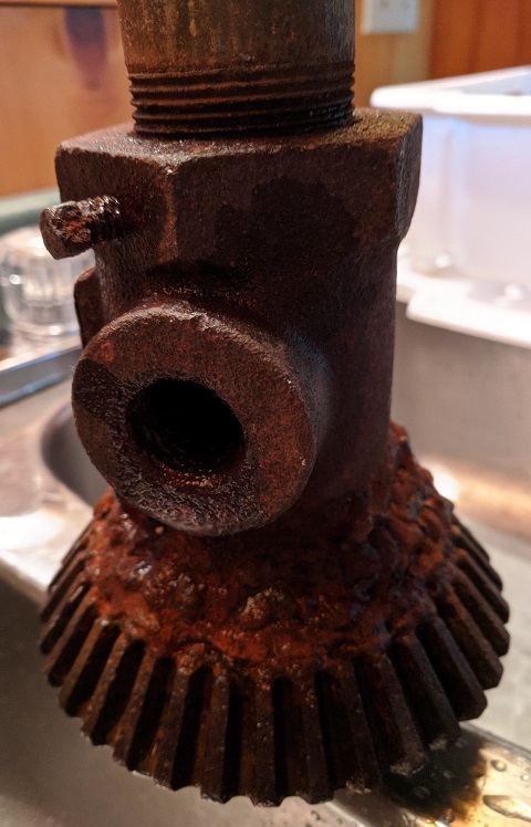
The housing, hub and bell gear were cleaned of grease and most rust stains. In the picture the outer seal has been pulled from the housing. It looks and feels like an original. The inner seal is visible inside the hub well. It is clearly not the original. Since it's in good condition and is difficult to remove I left it alone. I may need to replace the outer seal.

I had to go back up the tower to retrieve the drive shaft to investigate how water got past the seal that I made. There's a picture of how I designed the seal in the original article. An inspection revealed no mechanical deterioration since it was installed. Water got past it anyway and I needed to know how.

I repeatedly poured water down the top end of the pipe to see where it went. It all exited from the side drain holes and down the bevel gear splines. That's as it should be. No water made it past the welded barrier inside the bevel gear's inner cavity.

My suspicion is that the water that flowed off the splines and onto the plastic collar would, at least some of the time, travel inward rather than outward. Wind may be a factor. There is some evidence of debris and rust stains on the hub's crown gear that is consistent with the possibility. 

I will look into a better way to spill the water off the splines to ensure water can't flow inward towards the hub. I will also cap the top end of the pipe so that less water can follow this route. There is more design work to be done but it's a solvable problem.

Inspection and initial cleaning

When it was refurbished, an extraordinary quantity of grease was packed into the gearbox. You can see some of that excess in a picture above. That is never necessary. A light coating on moving metal is all that's needed. The rest is wasted, and I wasted time and material removing the excess. All the rust found inside was residue when the rusty water that got in evaporated. The base metal in a prop pitch motor is highly resistant to rust. The stains were easy to remove.

Staring at the gearbox is not a good way to diagnose problems. Neither is moving the parts by hand. About all I got out of it was greasy fingers. I continued the work wearing latex gloves. At this stage I did not use solvent since the bearings are all open and removing grease from critical areas would reduce mobility and mask the underlying problems. I learned to live with the greasy mess.

Deep freeze

The weather is warm and the problems only manifest at freezing temperatures. Every home, including mine, has a suitable test facility: the kitchen freezer. With the major components separated, I wrapped each one in a plastic bag and left them to cool overnight in the freezer. I suggest you check with your family first before doing this to prevent domestic conflict!

The components sent into the deep freeze were the motor, high-speed planetary gears and low-speed planetary gears. The motor was first disassembled to check for water damage. Happily there was none other than rust deposits on the sealed bearing closest to the gearbox. The motor performed perfectly after being in the freezer overnight.

Before separating the planetary gear assemblies I cooled it in the freezer as a single unit. The next morning it was not possible to manually turn the main spindle. The problem was definitely in the gearbox, as I had suspected.

The planetary gears were separated by removing the pinned nut from the spindle (mentioned above). I used trick I found in an article. I loosened the nut by restraining the shaft with a long screwdriver inserted though an opening in the low-speed planetary gear housing and into the low speed planetary gear. This is easier than making a special tool to grip the other (drive) end of the shaft.

Problems were found in both planetary gear assemblies. In the picture, the low speed unit is on the left and the high speed unit is on the right.  The labels show what I found. Notice how frost formed on the bare surfaces of the cold metal. Even with perfect water protection there will inevitably be some water inside due to condensation.

I concluded that the planetary gears need to be fully disassembled for cleaning and repair.

Repair plan

As I write this, I have removed a few of the suspect bearings. As expected, several of them are rough or fully seized. The only reason they turned at all was because the high motor torque made them spin on the supporting pinions. The well lubricated pinions appear to have survived the abuse.

Whether good or not, I will remove and replace all the bearings with sealed units of suitable specifications. The bearings on the shaft and the high-speed planetary gears are the most critical selections since they spin as fast as 9,500 RPM.

Suitable grease for the shaft, pinions and gears must be found. The grease must adhere well, have a high temperature range and (for the high-speed planetary gears) perform well at high speeds. More than one grease may be appropriate depending on where in the gearbox it is used. There is no shortage of available products and I just need to conduct a few hours of research.

Grease, water and rust residue must be removed from all parts. A pail of solvent should suffice for most of the parts. Once cleaned, grease can be applied and the new bearings installed. I'll come up with a better waterproofing design and then test it rather than leave it to chance, the way I did last time. I may need a garden hose to simulate wind driven rain.

All of this work will take time, and it is unlikely to be completed until June. This time of year that is not a problem since there are few contests of interest to me and I am more focussed on 6 meter DXing and not HF. I have enough flexibility with the antennas on 15 and 20 meters to satisfy my short term operating needs without being able to turn the upper yagis of the stacks.

Expect another article when I'm done with the repair and reassembly.

Monday, May 9, 2022

Radiosport: The Future of Amateur Radio?

Amateur radio in 2022 is quite different from how it was decades ago. Many of us don't notice some of the important changes because they've been gradual. New hams only clearly see what is and not what was. Change is relentless, whether we like it or not. And change it must if the hobby is to survive when those of my generation age out of the hobby.

In the 1970s the HF bands sounded very different than today. Finding a clear frequency in the CW or SSB segments on 20, 15 or 10 meters, when they were open, was not easy! Hams were talking. There were conversations -- some short and some long -- and traffic nets going on wherever you tuned. DXpeditions were annoying to many hams because they took up valuable real estate. Contests caused many to rage.

In Canada we were privileged in that most US hams were not permitted SSB below 14.200 MHz. Even so it could be tough to find a frequency to chat with friends. Newer hams might find this surprising since the situation today is very different. Although I must say that the lower HF bands were not so different than they are now with respect to activity level, be it SSB or CW. Calling CQ DX on 80 or 40 meters CW is about as likely to get a response now as it was decades ago.

Getting back to the high bands for a moment, I am struck by how little activity there is most of the time. Tune the VFO across 20 meters on most days and you will hear a lot of hiss and a few QSOs. That said, if you call CQ, and especially if you're spotted, you will get a response. Most QSOs are short, rarely more than a signal report and name, and both parties move on. There are fewer conversations. I don't particularly mind since I've never been overly fond of rag chewing on any mode. When I operate FT8 on 6 or 160 meters, it is no different than my typical CW QSO of exchanging call signs and signal reports.

Of course not all of us have the same interests or the same operating preferences. Differences are not absolute since we may do the same things but in different proportions. For example, I may chase DX for 50% of the time and contests the other 50% of my time on air. Your split might be 80% and 20%, respectively, and perhaps 10% to 30% of that for general conversations.

When I look at the hobby I see several categories of hams. They are distinct but there is a lot of overlap since few rigidly stick to just one style of operating.
  • Communicators: those who like to chat with other hams
  • Technologists: builders, experimenters and those who simply enjoy using technology
  • Public service: provide communication at non-ham events and during emergencies
  • Radiosport: competitive radio, including contests, DX or other award pursuits

Crossover is common though not always visible. There isn't much "communication" happening during the frenzied activity of a contest, but it is happening. Contesters are very social and talk to each other a lot on non-radio channels, social gatherings and in the team spirit of clubs and multi-ops. At hamfests, club meetings and at events like ARRL Field Day, hams of all interests socialize. 

Sometimes the mixing isn't without a little friendly teasing or friction. I have seen Field Day planning get heated when the contesters want to maximize the score, the public service conscious focus on operating procedures and emergency power and equipment, and the communicators just want everyone to have fun, family included. We still manage to get along most of the time.

Our distribution among the categories is not what it once was. It has changed over the years and it is continuing to change.

  • Communicators: once prevalent it is now less so
  • Technologists: the percentage may have changed little, but the technology focus is different
  • Public service: there remains a core need but daily traffic handling has become quite rare
  • Radiosport: more popular now than it once was

When I became a ham 50 years ago the bands were full of communicators. Kids my age started as communicators but many soon shifted to technology and radiosport. My initial draw was the ability to communicate. It was jaw dropping to hear a voice, in real time, from another country far away and, more incredibly, be able to talk to them. 

Recall that there was no internet or smart phones. Computers were large mainframes that were rarely seen. It was difficult to call someone beyond Canada and the US on the phone. Communication was a unique attraction of the hobby. It was possible to talk to hams in "enemy" countries like the USSR.

Today, communication by amateur radio is less of a draw. You can still see a kid's eyes light up that a box and a bit of wire can be used to speak to someone far away. Since there are now many easier ways to do that, that aspect of the hobby doesn't hold the attention of most for long. Technology is often the bigger draw or, perhaps if guided by an adult family or community member, many get hooked on public service. Interest in radiosport is more likely to arise after becoming licensed.

In may respects amateur radio is more a hobby now than it has ever been because there are everyday alternatives to what it offers, and those alternatives are commonly seen as superior. People still sail sailboats, program Amiga computers and play vinyl disks, but it is out of personal interest rather than necessity. 

By 2050 I expect there will be tube rigs lovingly maintained by aficionados, and there will be CW heard on the air. These activities are likely to become anachronisms and not mainstream. You will have to search for others with similar interests. Call CQ on CW in 2050 and I suspect you will be unlikely to receive a reply unless you have made a schedule with someone with the same rare interest.

Public service is gradually fading. In the developed countries, emergency radio systems and equipment are far better than they once were. Trained professionals can increasingly do most of the needed communication without calling on a volunteer force of communicators. Systems interoperate better than ever so that police, paramedics and public agencies can coordinate directly, whether by voice, email, video or other digital modes. Having hams as a fallback won't soon disappear but we will gradually decline in need and importance.

Technology will likely remain a draw to the hobby. These days it is more about software, exploiting the internet to augment operating activity, making controllers for remotes and so forth. Some continue to enjoy designing analogue circuits and building kits. Antenna experimentation also appears to be holding steady even though modern modelling tools have removed the mystery that once pervaded the field. All that said, the proportion of hams who have technology as their main pursuit does not appear to be increasing or decreasing.

Finally we come to radiosport. Regardless of your feelings about it, it is one activity that has been growing. There are more contests than ever, and activity in each shows steady growth. Participation is even up among the older generations who are looking for new ways enjoy their retirement. Competition has always been a draw for youth, be it sports, games and, yes, amateur radio. It was the same for me and my friends when we were new teenage hams.

Radiosport goes well beyond weekend contest activity. You are likely involved in radiosport even if you don't think of it that way. Consider the following:

  • POTA, SOTA, F&F 
  • DXCC and its many sub-pursuits: bands, modes, QRP, etc.
  • IOTA, VUCC, WAS, oblasts, counties, and other "entity" awards
  • QSO parties, regional/country activities, special event stations

Radiosport is claiming a large and growing share of our on air activity. For me and many others, it encourages skills development and station improvement. Some are motivated to develop innovative and sometimes controversial technologies to improve scores and chase awards. Others focus on improving their skills rather than increasing their dependence on technology. 

As amateur radio ages gracefully and becomes a less critical resource during disasters or to simply communicate across our vast world, expect radiosport to dominate. Amateur radio may become an activity like sailing once its vital role in society has been replaced. It's a monumental change for amateur radio that worries many who love the hobby. Yet change can also mean that it survives well into the future. Amateur radio is educational, competitive and challenging.

Of course there will still be communicators simply because both technology and radiosport need an outlet: technologists want to put their skills to practical use and radiosport participants need to talk to others. Beyond that? Not a lot is my guess. Expect the bands to be far quieter in 2050 except when a radiosport event takes place.

Absent the transition to radiosport, amateur radio may well fade into the history books within a few decades. Embrace change and share your joy of the hobby with others to keep it alive. It's worth saving and radiosport may be the best way to make that happen.

Saturday, April 30, 2022

Direction Pot for an Upside Down Prop Pitch Rotator

Prop pitch motors make excellent rotators for the very largest antennas and rotating towers. The DC motor is powerful and the gearbox has exceptional torque and turns at just the right speed. What they lack is a convenient means to attach a mast and a direction indicator.

There are two ways to drive a mast -- I have one of each: 

In both cases the weight of the mast and antennas and radial thrust are supported by bearings. The motor is only designed for torque.

There are several ways to add a direction indicator to a prop pitch motor:

  • Magnetic sensor on the motor axle that pulses on every motor rotation. The motor spins at ~9500 RPM (0.1 ms per rotation) so the technical requirements are non-trivial. Perhaps the most common example is the control system sold by K7NV.
  • Magnetic sensor (compass) mounted on the antenna, which communicates by wire or, in some cases, by radio. There are numerous products available of diverse capability and reliability. One successfully used by a few hams that I know is the magnetic sensor sold by 4O3A.
  • Use a belt or chain drive around the mast to drive a potentiometer. I don't know of any commercial products, and most everyone builds it themselves. It isn't difficult but there are different methods. Making it mechanically and electrically reliable is the challenge.

I chose the last option since it's inexpensive and I enjoy home brew projects like this. The challenge was to design a belt drive system for the pot, which is unlike the method I used for the chain drive system on the other tower. 

Getting the unit built took longer than it ought to have taken because I fidgetted over the design and then winter arrived. Now it's done. It was a nice little project to start the tower season with. The system is simple, the details are critical to success.


We'll look at the belt and tower mounting shortly. Let's first review the details.

The C-shaped steel chassis was pulled from my junk box. It's the right size and it's rigid enough for the application. I didn't saw off the "lips" on the left since they aren't in the way. If you don't have a similar scrap of metal handy it isn't difficult to fabricate or purchase something similar. The hold down screws and nuts for the bearing are #6 stainless. The holes in the steel chassis are large enough to allow the inner ring of the bearings to spin freely.

The pulley was found in a local farm supply store. For the 2-⅞" mast, there is about a 2.5:1 drive ratio. The pot turns ~2.5 times for a 360° rotation. The 10 kΩ linear Bourns pot has a 10:1 reduction drive, so this equates to a 2.5 kΩ range, or a 3 VDC range with a 12 volt power supply. Doing it this way supports over-rotation and improves resolution when applied, with suitable voltage division, to the 10-bit ADC of an Arduino. Should I decide on a software controller of this type, the ultimate resolution is about 2°. That's more than adequate for HF yagis.

There are ¼" sealed bearings at the top and bottom of the ¼" aluminum drive shaft. There is no friction with normal or excess belt tension, and no radial force on the pot. The shaft is slightly oversize due to the mill finish. This came in handy since only the section that fits inside the bearings must be reduced. I mounted the shaft in a drill press and used a flat file to remove material. A metal lathe is the proper tool, but for this small job the drill press worked well. 

The shaft bottoms in the lower bearing at the transition from the turned down section. Those stops ensure the mast sits firmly within the bearings without slipping. The pulley has a ½" press fit bore. A reducer was made with 1" lengths of ½" and ⅜" tubes slit along their lengths. I have a box of tube scraps from my many yagi projects. The 5/16" set screw was fabricated from scrap screw stock by cutting a slot for a screwdriver. A few minutes of work saved a trip to the hardware store.

The bolt on the left connects to angle stock attached to a tower girt (see below). Moving the position of the inner nut adjusts belt tension. The hole in the chassis was already there and it was perfectly placed for the bolt.

The bracket for the pot must be carefully bent, drilled and attached so that the pot and shaft are aligned over the full range of rotation. I made the mounting holes larger than required for adjustment room. The bracket is made from ⅛" aluminum stock. Final alignment required careful bending in a vice to make the top and bottom faces parallel. The ¼" shaft coupler is a flea market special. In the final installation (see further below) I used stainless screws cut to size.


Here we see the completed unit mounted on a tower section that I keep as a jig in my workshop. The pipe is manually turned to mimic mast rotation.

As you can see, the belt doesn't need to be anything fancy! The friction due to the pulley, bearings and pot is so low that almost anything will do. The knot passes the pulley without any problem. I will eventually come up with a better belt. Initial testing suggests that the rope belt does not creep down the mast as it turns if the belt isn't measurably slack. I may add a thin flange around the mast to make sure that it stays in place.

Alternatives to a rope include a V-belt, an adjustable belt and a rubber band. Finding a V-belt of exactly the right size is difficult and there is no good way of getting it around the mast and pulley. The adjustable belts I've found online look promising but they are very expensive. I tried rubber strips from my junk box and found that the excellent grip caused them to easily derail by riding up the pulley rims. Rope is cheap, easy to fit and won't jump out of the pulley.

For weather protection, the unit is mounted on a tower girt to place it directly beneath the plate for the middle mast bearing. The pot is wrapped to resist corrosion from moisture, which is a common problem for pots located outdoors. The plate and girt should offer sufficient protection to the pulley and belt from wind driven, rain, snow and ice. I won't know for sure until it survives a cycle of the seasons. 

The pot slider is grounded, both to the tower and via a control cable wire. Several feet of Cat5 run from the pot to the termination of the main run of control cable. There I spliced the wires into the bundle. The other wires of the control cable are for the 15 and 20 meter stack switches.

The bit of scrap rope I used for the belt is temporary (ha!). It was about the right length so I carried it up the tower and wrapped it around the mast and pulley. That double granny knot is not going to last long! I just want it to last long enough for for the first phase of testing and experimentation. It is easy replaced.

Lucky for me, when I did the control cables for the 15 and 20 meter stack switches I made sure that all wires of the control cable were connected from the tower top to the shack desk. It was easy to turn over the "temporary" stack switch controls to access the 3 wires (pot slider is grounded) and measure the resistance as the motor is turned. So far so good.

Software controllers for the two prop pitch motors are an item in my 2022 station plan. I have the chips and other components, but not the software or hardware UI (user interface). I haven't yet decided whether to go fully with software, as with the ongoing antenna controller project, or a mix of hardware controls and software. I'll build a prototype or two before deciding on a final design.

Expect an article later this year once I have a prototype controller. It'll be nice to get the large and retro controller relegated to below the operating desk rather than adding to the clutter on top of the desk.

Saturday, April 23, 2022

More Cable, Another Trench

I've dug trenches to bury a many long runs of cable. It isn't an easy job so I always add extra cable for future expansion. Since predictions about the future rarely work out, I inevitably require more cable than originally foreseen. Hence, more trenches.

Last week I dug a new trench to the 150' tower. When the trench was first dug in early 2018 (cables were on the surface for the tower's first winter) I laid down 4 runs of Heliax, 2 Cat5 control cables and cable for the prop pitch motor. 

Since then, I fully occupied the second control cable for the Beverage remote switch, which itself required a new trench. Last year I ran a new cable for the side mount TH6 rotator. I used almost every other control cable wire for the rotator and for the planned 10 meter stack switch.

One of the Heliax runs is ½" flex, which is not rated for burial. The price was right, I was in a rush, and despite the inappropriate burial it is still doing well after 4 years underground. Nevertheless, a replacement for it seems wise with the new trench prepared. Another Cat5 cable joined the LDF5-50A, and of course the 14/2 cable for the Ham-M rotator.

Refer to the earlier article and you'll notice how the routes of the two trenches differ. The photograph and way points guided the route of the new trench. I realized I might need a second trench when I dug the first. I planned the route of the first trench to easily accommodate this, the second trench.

It's a good thing it's just hay in the field since the plants are perennials and there is no need for the soil to be overturned for planting. Disturbing the soil to that degree is incompatible with buried cables and radials.

The first trench was dug with a small trencher (there's a pic in that earlier article) that I rented for a good price. Although it did a fine job, it was heavy, tiring to operate and it destroyed the surface vegetation. For the second big tower, the trencher was no longer available and I had time on my hands since the pandemic lock down had just begun (spring 2020). I picked up a shovel and pick axe and got busy. 

It was a lot of work, but not as much as I feared. That 170' long trench contains 3 Heliax runs, 2 control cables and a spare cable for a future side mount rotator. When the sod was replaced the hay quickly resumed its spring growth. Trenches dug by the trencher were barren of hay for the first season.

Although I am not shy of manual labour it is no easy choice to pick up a shovel rather than rent power equipment. However, my source dried up so that an economical rental was not available. At the time I believed that I would merely save money by digging the trench manually. The advantages were more than I anticipated:

  • Low cost, if you have the time and endurance
  • By using a spade the sod can be saved for rapid surface remediation
  • There is no rush: work for an hour, rest and continue when you're ready, without regard to a ticking clock when you are using a rental
  • Save the time of trencher transport (if you do it yourself), maintenance and cleaning and dragging it around the property
  • Quiet and no exhaust fumes!

Despite not having timed myself, my guess is that the time investment is not very different for a shovel versus a trencher. Larger trenchers are self propelled, which would save time but those are more expensive. A shovel really isn't all that slow. If you are physically unable to do it, a trencher makes sense. 

There is no equivalent comparison for digging holes for tower bases since small backhoes make a mess. You'll likely need a wood form to pour the concrete. With a shovel you can make a "mud hole" that is far more precise and doesn't need a form. That can be well worth the effort of manual digging. You can also hire labourers to do it if you can't do it yourself. A trench does not need to be so precisely made.

In the trench picture at the top and the one at right (late fall of 2017), you can see water in the open trench. It inevitably rains before the trench can be back filled. Notice that the cables have been laid in the waterlogged hole regardless. 

If you feel leery about that, perhaps it's because you're not using cable that is rated for direct burial. Cable rated for burial will not be bothered by the open water or by saturated soil when it is buried. Spend a little more on the cable and you won't have to redo the job in a few years. That said, I often use unrated cable for low voltage AC and DC with an unblemished PVC jacket. So far so good, but don't expect miracles.

There are many stones below ground, both large and small. I remove the small stones but the big ones pose a problem. Most of the time I shift the trench several inches to route around them. Trenchers have enough power to remove many of the big stones that I wouldn't bother with when using a shovel.

There are other methods to bury single cables and wires where depth is not critical. In that first referenced article I demonstrated my mostly failed attempts to mechanically dig narrow and shallow trenches for radials. It did not make the job easier. It is better to lay radials on ground, pin them to the sod and let the vegetation grow to cover them. I have yet to snag a radial with the riding mower.

Another method is to slit the sod. I use the lawn edging tool shown at right. It takes very little time to cut a slot across the lawn. This is how I buried the burial grade cable for the new terrestrial wireless internet equipment that was mounted on the Trylon tower. It works best for narrow cables like Cat5/6/7 and RG6. It's impractical for thick cables and cable bundles.

Make the depth consistent since the half-round blade doesn't cut deep along its full width. Wiggle the tool to widen the slit. A length of thick steel (at least ¼") is used to push the cable into the slit. Keep a screwdriver or similar tool handy to cut the dirt missed with the edging tool. Do not bend or stress the cable by forcing it in. Clear the obstruction when you run into resistance.

One final job that I've been putting off for a long time is burying the multitude of cables from the stone wall surrounding the lawn to the Trylon tower. The weight of the cables adds up and it's becoming so heavy that I am uncertain how much more the aerial run with its steel messenger cable can withstand.

The biggest impediment is the 20 yd³ of topsoil in the way. It was there when I purchased the property and I gave it little thought at the time. A second problem is that the roots of the birch trees run close to the surface and they surround the wall. I've already had to deal with them on the outside of the wall -- the wall foundation isn't deep enough to block the roots. I cut the small roots and route around the larger ones.

The dirt pile can be moved with a small backhoe and I have a landscaping project that needs the soil. The birch tree roots are a more difficult challenge. It is unlikely that I'll deal with it this year. 

An alternative that I might choose is to increase the aerial run strength. A trench cannot solve all problems, and there is a benefit to having easy access to the cables for maintenance and station reconfiguration.

Friday, April 15, 2022

FT8: What's That Sound?

While I ever so slowly ease back into spring tower and antenna work, the technical articles are slow in coming. They will return! But for now I have another article about operating, and in particular about operating FT8. This is timely since 6 meters is intermittently open to South America and sporadic E season is a few weeks away.

Have you ever worn headphones while operating digital modes? Few do since there is usually nothing worth listening to. The software does all the work. About the only time I do it is when I want to quickly check 50.313 MHz for activity. When nothing is heard I flip back to HF and conventional modes.

Another good reason to listen is to monitor your own signal. Is the audio distorted? Is there power line hum? Is the microphone live? Almost all of us use SSB on our transceivers to operate digital modes, and our signals are subject to the same problems that are common on phone. I expect that rig technology will evolve to improve digital mode operation, but for now we must be careful since the SSB set-up is different for phone and digital.

Since SSB bugaboos have been discussed from time to time on the blog, I will only briefly mention a few items: disconnect the mic, disable the speech processor and keep the average power well below the CW or PEP peak power capability of your transmitter and amplifier.

Now let's move on to several items that seem to be increasingly common on the digital frequencies.

I hear voices

The FTdx5000 I use for digital modes has the front mic jack live at all times. The buffer amplifiers for the mic jack and rear audio input jack are mixed and there is no possibility to disable one or the other. Many rigs are similar. It is critical to unplug the microphone on the majority of rigs when digital modes are used. The computer software should be the only audio source.

Yet many forget. I do it occasionally since it is so easy to forget. Put on your headphones and listen to any busy FT8 channel and you will often hear background shack noises and conversations. Most hams realize their mistake and correct it. Unfortunately there are a few who never do and woe to those who tell them! Unless the signal is local and strong you may have difficulty identifying the guilty party.

You have mail!

Most of us use Microsoft Windows on our shack computers. Windows handles peripheral equipment with a great deal of flexibility so that it is responsive to the behaviour of most people. It deals with audio devices and sound cards being attached and detached, along with their various driver and configuration requirements. That doesn't always work for hams and others with very particular requirements for their audio devices.

Windows has a designated default sound card. It is typically on the motherboard, and uses the front or rear audio jacks. When there is more than one sound card, on the motherboard or added by the user, the default can be changed, and the change can cause problems. The default sound card is the one that Windows uses for notifications. These include the "bong" sound when you do something wrong, the chime or voice announcement when an email arrives, among many others standard applications. 

In most installations your digital software uses the default sound card. When Windows notifications occur during a transmission they will be transmitted. That's not good! There are ways to prevent it by delving into Windows settings or with additional hardware.

Since I don't have multiple sound cards on my current shack PC, my solution is to disable all Windows audible notifications. It works for me, though others may not like doing that. An alternative is to have two or more sound cards and use a non-default sound card for the rig interface. Many recent generation rigs include a sound card in their USB interfaces so you don't have to go out and buy one. If your rig has it, use it.

Courtesy tone

Modern transceivers have a plethora of features that almost nobody uses. One that should never be used on HF is the courtesy tone. This is the feature that transmits "beep!" when you release the PTT. It was popularized decades ago on VHF/UHF repeaters to make explicit when a transmission was over. The use of squelch on FM can make the end of a transmission difficult to deduce without it. On SSB it is not necessary and, in my opinion, it sounds ridiculous.

When you switch to digital modes, of course using the SSB mode of the rig, the courtesy tone feature is applied if enabled. In most instances it does not cause QRM because everyone's transmissions are synchronized. However, it is still poor operating practice and locals in particular will have no difficulty identifying the culprit. Don't use the courtesy tone feature and this won't happen to you on FT8.

Text to speech

We have some wonderful tools at our disposal to improve our results at gathering DXCC countries, grid squares, states and many other awards. The ability to passively monitor all activity on an FT8 channel can be exploited to further those aims. There are software applications that will monitor the messages decoded by WSJT-X, look up the call signs in local and remote databases, and issue notifications when a station is needed for one of those awards.

Many times I've heard these announcement on FT8 channels, and in one case from two stations at the same time. Not only does this interfere with others, it also halves the periods that you are monitoring since the transmissions exclude the possibility of listening during those periods. Unless you can route the notifications over a different audio path than that for the received audio, turn off those features.

Voice announcement features of modern transceivers can also be a concern. Features that are so useful to blind hams have found use in many shacks. With the features enabled, the rig will audibly announce the frequency, mode and other data. Depending on how the audio is routed between the rig and PC, these announcements can inadvertently be transmitted when using digital modes. 

Every rig is different and I don't have or use these features, so I cannot offer a recommendation other than to turn them off when you don't need them. For audio routed to the PC on digital modes, you might not even notice that it is happening unless you check for it.

Sound card shuffle

Among its many peculiarities, Windows is notorious for reordering, renaming, reconfiguring and renumbering peripheral devices during periodic updates and sometimes over a PC restart. It isn't noticed by most people since it doesn't affect their use of the PC. It is difficult to predict when it is likely to occur. You must be observant.

As mentioned earlier, Windows usually does it to transparently deal with what it believes are potential trouble points. With our particular computer interface needs in the shack, we need to prevent or recover from what Windows chooses to do.

With digital modes pay particular attention to sound card names and ordering. With many sound cards, it is a good idea to check the default and sound card assignments after Windows updates. There are security products that can disturb your configuration and those settings will need attention as well.

Monitor your transmissions

Almost all of the aforementioned problems can be discovered by monitoring the transmitted audio. Use the rig's monitor feature from time to time to ensure that the transmitted audio is clean and uncluttered by extraneous audio sources. This is especially important after you've made configuration changes on your rig, PC or software applications. It isn't something that needs to done all the time so it shouldn't be a burden.

It is sad to say that few hams pay attention to their transmitted signals, be it to check for distortion, key clicks or inappropriately routed audio. In some cases it is necessary to listen on a separate receiver since not all potential problems can be heard using the rig's monitor feature. Alternatively, ask a friend to listen and let you know if anything is amiss.

Thursday, April 7, 2022

CW Competency

I have an admission to make. Although I love CW, use it a lot (starting in 1972!) and I can comfortably operate at high speed in a CW contest I am not a very good CW operator. Outside of contest exchanges my sending is often full of errors and copying ordinary conversation text is not great.

The problem isn't really lack of ability but lack of practice. When I use it a lot in daily operating, as I did early in my ham life, I do better. I no longer practice at high speed very often. Some evenings I will listen in on a high speed CW QSO -- 40+ wpm -- to see how well I can do. Depending on my mood and alertness I often do pretty well. 

Sending is a different problem. Outside of the 20 to 35 wpm range my error rate climbs. Both high and low speeds are difficult because my fingers are unable to get the timing right until I adjust the speed at which my mind is thinking. During conversations, I make flubs when I think of the spelling of words or I lose track of the sentence because it's so much slower than spoken conversation.

In the heat of a contest my ability to copy fast CW improves. Everything is fast in a competitive event and my reaction time improves. QSOs are structured and there are few times one has to send or copy anything different. Jumping on the paddles at that speed can be comical as I struggle to move my fingers side to side rather than up and down on the keyboard. I do better to avoid the paddles to keep my sending clean. 

About the only time I hit the paddles is to greet a friend or to send a partial call while running. I avoid even that when I do SO2R since I am not always certain which radio the paddles will key. Like most contesters, I strive to use the paddles as little as possible.

All that said, am I really so bad a CW operator? How should one assess ability and performance? You and I may have passed a code test years ago, but that says very little since the speed was slow and the content uncomplicated. 

It is surprisingly easy to get by in a CW rag chew by bungling up to half the characters received (or sent, for that matter) since context allows us to fill in the rest. When we only respond to the bits we did copy, our QSO partner will usually be none the wiser, and vice versa.

The difficulties I run into during a CW rag chew -- I'm mean a real conversation -- include:

  • CW is far slower than a spoken conversation or reading text, and I often lose the thread of the received sentence by the time it reaches the end. This applies to sending and receiving
  • Poorly sent CW makes me puzzle over a character or word group, and I may then lose the context or the gist of the sentence, or I miss the next several characters or word and so lose it entirely. These sending errors include run together characters and words, backing up to resend a word in which a error was made without an indication that that is the case
  • My attention wanders since the flow of the conversation is so much slower than when spoken. That causes more mistakes.

I am far from alone with these difficulties. That said, I do well in CW contests. In those events there is no rag chewing so those problems don't apply. The pace is fast and I can stay focussed for hours at a time. CW competency is measured differently in a contest:

  • Copy a call sign or exchange (some are quite complicated), at high speed the first time
  • While running, copy one complete call on the first try when many stations are calling and there is QRM or QRN
  • While spinning the VFO, copy a call sign on the first try, identify the station as having completed a CQ or at the end of a QSO, and make my call immediately
  • Pull an exceptionally weak station out of the noise level and correctly copy the call sign and exchange
  • During SO2R, interleave two CW QSOs and, when receiving on both radios at the same time, copy call signs and exchanges of both

Since I am better in contests than in coversations, am I a competent CW operator? If I'm judged to be lacking in competency in either category, am I truly competent? When I jump on the paddles to send something not in a pre-programmed message and I mess it up, is that incompetence or just momentary clumsiness?

Competency in any skill is a matter of practice and critical self examination. Without self examination, no amount of practice will help. Tune across many very active CW stations and you will find at least a few operators who have probably never listened to themselves and remain blissfully unaware about how hard they make it for others to copy them. I wonder if they care. There is no hiding from poor copying ability and that is what many focus on rather than accurate sending.

There is no need for perfection. It's a hobby and CW is a pleasant if archaic method of communication. It is not obsolete in amateur radio since it has the same advantages for weak signals and crowded band conditions that it had a century ago. It particularly shines in contests and DXpeditions by neatly sidestepping accents, languages and QRM. 

CW remains my favourite mode despite my inconsistent use of it and rare engagement in rag chews. But when I do use it, I love it. When it comes to competency, it should be no surprise that I am more interesting in improving my contesting effectiveness. My rag chewing CW skills lag and may never improve. My conversations are done with SSB.

Wednesday, March 30, 2022

Interactions: Degrees of Degradation

Everything interacts with everything. When you swing a hammer the moon jumps. The laws of physics tell us so. It's a matter of by how much: some interactions are stronger than others!

The same applies to antennas. Antennas interact with everything, including that hammer. The critical metrics for the interacting object include:

  • Distance
  • Resonance
  • Material characteristics

It is not true that non-resonant conductors and insulators don't interact with an antenna. For example, a long plastic tube 10 meters from a 20 meter dipole has negligible interaction. But wrap that tube around the dipole and its effect is very apparent. A dielectric in the near field of a radiator reduces the VF (velocity factor) and a fraction of the energy, depending on the material's dielectric properties, will be dissipated as heat. We need to take care when selecting insulated wire for our antennas.

The Earth itself interacts with our antennas. Ground proximity and quality similarly affects verticals, their radials and really any antenna. Its proximity, dielectric properties and conductance can have a profound impact on loss and resonance, often far more than interactions with other antennas.

The same is true of non-resonant conductors. A short conductor near the tip of a 20 meter yagi element will alter the resonance of the element and thereby impact performance of the yagi. It is never invisible. But move it a few meters and, again, the interaction is negligible. The conductor can be a 2 meter dipole, a segment of a broken up steel guy, a power line or a metal clothesline. 

Interaction is not a binary phenomenon: it's a matter of degree. It varies in accord with the previously listed metrics. Some interactions are easy to mitigate by, say, moving an antenna or interacting object a short distance. In other cases the impact of the interaction may not be concerning and therefore not worth the trouble of taking corrective action. Only you can decide. There is no one right answer.

Analysis and mitigation of interactions has been a recurring topic for this blog. Type interaction into the search box and you'll see. Examples include this, this, this, this and this, and there are many more to be found here and elsewhere in the ham literature. No matter how small or large your station it is worthwhile to give interactions some thought. I did it when my station was small and I do it now that my station is large. The only difference is that my objectives have changed.

In this article I will focus on two type of interaction, using a reference 3-element 20 meter yagi:

  • Parallel 20 meter dipole in front of the yagi
  • Parallel 40 meter dipole in front of and above the yagi

These will highlight "worst case" resonant interaction and non-resonant interaction, respectively. The characteristics of these simple interactions are both interesting and illuminating. Mitigation will be touched upon but not discussed in depth.

Parallel antennas resonant at the same frequency is a worst case scenario. Interaction is guaranteed. It is so severe that its effects are clearly discernible in the model with the dipole up to 20λ (400 meters) ahead of the yagi, rippling the azimuth and elevation patterns. The yagi azimuth pattern at right is for a separation of 10λ (200 meters). Resonant interactions have a long range! On the left the separation is reduced to 1λ (20 meters) to show the induced current when the coupling is extreme.

The antennas are placed 15 meters above real ground (EZNEC medium ground). This is more realistic than in free space since the ground reflections that are responsible for the elevation pattern (lobes and nulls) distort the pattern in a particular fashion. Height and antenna separation are important factors, however this aspect will not be isolated and studied in this article. But please keep it in mind when you plan your antenna farm, be it large or a small one.

The elevation plot shows the degree of pattern distortion due to interactions, with the dipole placed 200, 100 and 40 meters directly ahead of the yagi's centre. At 200 meters (10λ) separation there is a just a slight wiggle to the yagi's pattern. At 100 meters (4λ) the wiggles get larger and the increase of side lobe magnitude (more is visible in the azimuth plot, which isn't shown) steals 1 db of forward gain. At 40 meters (2λ) the wiggles are gone but the pattern distortion is severe and gain is sharply reduced.

Conservation of energy applies. Energy that balloons those side and rear lobes and fills in the nulls is not available for the main forward lobe. Interactions degrade both the pattern and the gain.

Of further interest is the effect on the yagi's impedance. The separation is 40 meters for the SWR plot above. At the design centre of 14.125 MHz the resistance drops from 37 Ω to 30 Ω while X barely changes -- for simplicity, the model uses a transformer to take 37 Ω to 50 Ω. Another important change is the antenna's Q, which has noticably risen. The higher Q reduces the SWR bandwidth. 

By modifying the transformer, the SWR can be brought back down to 1 at 14.125 MHz. However, the SWR at 14.0 MHz still increases from 1.2 to 1.4, and from 1.6 to 2.0 at 14.350 MHz. With the seemingly large 2λ separation there is enough coupling to significantly alter the yagi's impedance and Q. The situation rapidly deteriorates at closer separations.

There is a lesson here with regard to resonant interactions. As the interaction increases (separation decreased in this example), we see the measured deterioration occur in the following order:

  1. Side lobes and nulls (or RDF if you prefer)
  2. Forward gain
  3. Impedance

Which is to say, trying to detect interaction by measuring the impedance or SWR is ineffective except in the very worst cases. Antenna performance can degrade quite a lot without any change in SWR. In this example, the SWR barely changes at separations of 60 meters (3λ) and greater. I had to reduce the separation to 40 meters to see a significant change in the SWR.

The metrics for non-resonant interactions are different. Let's briefly explore that interaction by replacing the 20 meter dipole with one for 40 meters. Although 14 MHz is the second harmonic of 7 MHz, you have to go to the odd harmonics, starting with the third at 21 MHz, to have a resonant interaction.

As expected, the interaction with a non-resonant antenna is weaker. It is so weak that we have to bring the 40 meter dipole closer than 1λ from the 20 meter yagi's centre to see appreciable pattern degradation.

The yagi's impedance is similarly less affected by close separation. The SWR plot is for a separation of only 10 meters (½Î») from the yagi's centre. Unlike the case with a resonant interaction the effects on pattern, gain and SWR for a non-resonant interaction like this one tend to occur together while varying the separation. When stacking the dipoles on the same mast or tower (above rather than in front) the interaction is lower for both cases since the yagi has a weaker field in that direction. That's been discussed in previous articles on interactions so I won't say more about it in this article.

If the interaction is concerning and the antennas must remain in their position there are methods for reducing the interaction to an acceptable level. The obvious one is to make a resonant interaction non-resonant by loading the antenna elements for the lower band to shift the harmonic resonance out of band. This is what I did to my 3-element 40 meter yagi to remove its affect on the 15 meter stack. 

If the non-resonant interaction is with a guy wire segment or other part of the near environment you may have fewer options to reduce the interaction. You may have to live with it since those "fixtures" can't be moved. But do measure the impedance and build models if possible to remove the uncertainty. The degradation may not be as bad as you fear.

Let's consider another alternative that some hams have chosen. I will make a simple change to both the 20 and 40 meter dipoles at their closest separations of 40 meters and 10 meters, respectively. The interaction with the modified 40 meter dipole is on the left and on the right is with the modified 20 meter dipole.

The change to both is that the dipole has been cut open at the centre. This is done with a high resistance load in the EZNEC model. That's signified by the open box at the dipole centres in the antenna plots above. For those runs the resistance was 0 Ω, which leaves the dipole unaltered. Notice that the 40 meter dipole interaction worsened and the 20 meter dipole interaction has almost vanished. The SWR curves are not shown but show a similar response: better for the modified 20 meter dipole and worse for the modified 40 meter dipole.

In the case of the 20 meter dipole, opening the centre has converted the dipole into a 2 element collinear 10 meter array. When the same is done with the 40 meter dipole it becomes a 20 meter collinear array. At lower resistance values, including 50 Ω, the interaction is intermediate between these patterns and SWRs and the worst case scenarios described earlier. 

I am not including those additional plots in the article since they add little to the discussion. Modellers can easily explore those and more complex scenarios, including transmission lines and complex loads.

There has been some misunderstanding about whether interaction due to an antenna not currently is use can be mitigated by shorting or opening the transmission line or the antenna feed point. Opening the element is best but this is rarely done since it is difficult except, perhaps, for verticals by opening the connection to its radials with a relay. 

Doing it at the end of a transmission line -- most commonly at the antenna switch -- is not usually effective since the electrical length of the transmission must be considered, and it is rarely a multiple of ½Î». At other lengths, a short, open or resistor termination appears as a complex load at the antenna feed point. In any case, as stated above, any load on the unused antenna may only modestly reduce the interaction, and can make it worse. This includes a 50 Ω resistor, which some favour. This is easy to test by inserting various loads in the model.

A further difficulty is that this mitigation technique must be done for every element of an interacting yagi. Insertion of a load at the driven element or on the transmission line that would be effective for a single element antenna will be ineffective because the other yagi elements will still interact. You have to do all of them. For severe cases it is better to do what I did for my 40 meter yagi or, if you can, position your towers so that antennas that can interact are not pointing at each other most of the time.

Deal with interactions directly rather than by implementing token measures such as switchable loads in your antenna switch. Use those switches to ground unused antennas for lightning protection instead. We go to a lot of time and expense to design, build and raise high performance antennas so it makes good sense to effectively deal with interactions that degrade the performance. Anything else is wishful thinking.

Wednesday, March 16, 2022

South! 6 Meters Opens

It takes a lot of EUV to light up the ionosphere's F-layer bring 50 MHz signals down to Earth at my geomagnetic latitude. That happened this week for, as far as I know, the first time in solar cycle 25. Despite lasting only 3 minutes it made an impression on me. Here is what I found on my screen late afternoon of March 14 while I was busy elsewhere.

LU, CE and CX. It is the north-south path that is the first to open at this latitude as the MUF rises. Of course I cannot be certain that this is truly an F-layer phenomenon. There is TEP and southern hemisphere sporadic E that may be in play for part of the path. I can discount sporadic E at this end of the path since these openings have correlated well with the recent rise of the solar flux, and persistent for several days at a time of year when sporadic E is historically rare. Unfortunately for us the propagation only reached as far as the southern and central US.

It was no accident that I was monitoring the southern path. There have been ample reports of contacts between southern Europe and southern Africa, Japan and Australia and South America to the southern US. The propagation was there, tracking the solar flux and slowing creeping northward. Digital modes make it convenient to monitor the band to discover elusive openings while I go about my day. 

A friend has been using DXmaps (see screen capture at right) to plot the openings. He found them there as well. There are many tools available to help discover openings.

We are on the cusp of F-layer global communication on 6 meters. It will occur even if this solar cycle is no better than the historically weak previous cycle. What we probably won't get is extensive east-west propagation or on northerly paths from this part of the world. Time will tell.

The openings this week are most likely due to what I call the holy trinity of north-south propagation:

  1. Moderately high solar flux, in the vicinity of 115 to 120
  2. Equinox
  3. Aftermath of a geomagnetic disturbance.

The planetary K-index was at 5 to 6 for 15 hours the previous day. During each equinox period there can be extended north-south propagation after sunrise and before sunset, assisted by gray line propagation along a great circle that intersects both geographic poles. I was not surprised to hear and work stations from southeast Asia (YB, E2) on 15 and 17 meters early to mid-morning.

On its own a solar flux of 120 is usually inadequate to raise the MUF above 50 MHz this far north. The other two factors were likely needed to open the band. A flux of 140 would significantly raise the probability of an opening without other factors coming into play. That has only occurred once this. The other two factors were in play and 6 meters didn't open here. Over the two days following the March 14 opening, as we moved past the disturbance, there was nothing heard here despite the stable solar flux.

As the solar flux rises further we'll see propagation extend to the southeast and southwest. That includes southern Africa, Central America, W6 and New Zealand. As the flux rises towards 200 we should get openings to northern Africa, most of Oceania, southern Europe and, eventually, all of Europe. 

F-layer openings to Asia are unlikely if the solar cycle continues on its current track. Of course the propagation will be better further south. At the exceptional peak of cycle 22 in 1989/1990 there were only a few days when I heard Japan, and worked none of them. In contrast, I have around 100 sporadic E contacts with Japan, via FT8. Sporadic E will remain an important propagation mode even during the cycle's peak years.

My station is ready to go so I am eager for F-layer propagation to arrive. I need it to extend my DXCC count on the magic band since sporadic E is inadequate to reach most of the world. But I am eagerly anticipating its return in May. Sporadic E will remain the dominant DX propagation mode in 2022.