Friday, February 7, 2014

Height & Gain: 40 Meters Wire Antenna Summary

For those who have followed along I have written a number of articles over the past several weeks on one and two-element wire antennas for 40 meters. My objectives are particularly aimed at DX (low angle) performance and a single support for the antenna apex. Some of these antennas were only intended as references -- the dipole and inverted vee -- for the purpose of comparison.
[The TL;DR version of this long article is to just read the chart below. I at least want the long version to document my observations for future use. Others might not.]
This article is an opportunity to distill a few performance aspects of all these antennas in one place. The result is one (very) busy chart plus several discussion points. To introduce the chart I will make a few points, most of which have appeared earlier.
  • The elevation angle selected for comparison is 10°. This is the median value of measured elevation angles for medium to long path lengths at 7 MHz, which range from 0° to 20°. The peak gain is almost always higher than 10° but that is of no interest to me. The vast majority of antenna articles I've read focus on the peak gain at whatever elevation angle it occurs, but that is often not indicative of DX performance on the low bands where antennas are, for most hams, at low heights.
  • Ground, topography and "obstacles" in the environment of the antenna can have a strong effect. On this I had to compromise if the comparison is to have any meaning. I therefore assume a medium, real ground, as modelled in EZNEC, which is approximately what many suburban hams will have. I also assume that the ground is flat out to the horizon and that there are no obstacles that would shadow or couple to the antenna. This includes a tower or metal support for the antenna that might be resonant on 40 meters. In the real world where we all live these interactions are inevitably present. As a general rule, the lower the antenna the greater the interactions. Interactions are more than not reduce antenna performance, especially for arrays with two or more elements.
  • The loops and loop arrays are all fed for vertical polarization. When fed for horizontal polarization their DX performance (gain on the chart) would be substantially worse.
  • The interior apex angle of the inverted vees, narrow diamond loop and chevron loop is 120°. The explanation for this choice is in the articles of the associated antenna articles. In general, a smaller interior apex angle for these antennas result in one or more of reduced bandwidth (higher Q), lower gain at 10° elevation, and reduced F/B (for the 2-element antennas).
  • The gain shown in the chart for the 2-element antennas is at the frequency where it is maximum. It will be lower at other frequencies. You'll need to read the individual antenna articles for how the gain varies with frequency. 
  • All wires in the model are 12 AWG insulated copper, except for the chevron which uses thicker 10 AWG. Choice of wire affects element length and resistive loss. After decades of playing with antennas I have come to prefer insulated wires to keep corrosion at bay. This not only makes adjustments easier in the future (no sanding/cleaning) but also avoids resistive loss due to oxidation.
  • Links to the antenna articles: 2-element yagi with wire dipoles; 2-element yagi with inverted vees; 2-element yagi with diamond vees; delta loop; chevron loop; diamond loops; 2-element delta loop and 2-element narrow diamond loop.


Yes, it's a busy chart, but it isn't too difficult to unpack if you note that the dipole and inverted vee start from the bottom left and are roughly parallel, and the three 2-element yagis (dipole elements, inverted vee elements and diamond vee elements) start at the centre left and are also mostly parallel. All the loops and loop arrays cease to increase in gain as the height increases.

There are a few conclusions to be taken from this chart, which I'll list. Just keep in mind that there are a number of factors that could reduce the performance you might see in actual practice.

Gain Performance

If you must have gain, at any height, you should put up a wire yagi. While it may seem an expensive waste, a rotatable 2-element short yagi only 15 meters high will do very well. As you turn down the element ends, as you must with a fixed (or switchable) wire yagi, make the angle as shallow as possible. Alternatively, or below about 18 meters, a 2-element narrow diamond loop array will give about the same gain and superior F/B. But first test for tower resonance which would impact performance.

If you want to keep it simple and use a single element a vertically-polarized loop is the superior choice at heights below 18 meters. The choice of loop configuration is determined by how much F/S and low-SWR bandwidth you can live with, suitable tie-down points and interactions with the tower, a high-bands yagi above the loop and the local environment. The chevron loop offers the best gain but requires the greatest amount of compromise. The delta loop offers the best omnidirectionality but with unexceptional gain.

Copper Losses

Voltage Divider
Wire antennas are made from conductors that are narrower than found in the typical rotatable yagi made from aluminum alloy tubes. This results in resistive (I²R) losses that are higher than in the rotatable yagis despite copper being a better conductor than aluminum. Aluminum oxide, which readily coats the surfaces of yagi elements is a good enough conductor to not change this relationship.

Oxidized bare copper wires (cuprous oxide) have higher resistance, and therefore loss. The impact on low HF is usually not a large concern since the oxidation doesn't usually penetrate too deep and the skin depth is greater. Stranded bare copper is worse than solid bare wire since there is more surface area that will oxidize. I use stranded copper wire in most of my antennas, but I use insulated wire to avoid corrosion. There is dielectric loss in the plastic insulation, but it is small at low frequencies.

The resistive losses in the single-element wire antennas is typically no worse than -0.1 db, and so can be considered of no significance. The chevron loop losses are more significant, though still no more than -0.5 db, due to its low radiation resistance. The conductor resistance is in series with the radiation resistance, so as with any voltage divider circuit the lower the radiation resistance the greater the current and therefore the power dissipated in the conductor resistance.

In the 2-element wire antennas the impact of resistive losses is more pronounced since the radiation resistance is lower. This results in greater current flow and thus greater loss in the conductor resistance. This is not a large effect but is still significant. The typical loss figure for the 2-element antennas in this article is -0.3 db.

W8JI has a description of radiation resistance, height and loss you should consider reading if you'd like to learn more on this important topic. It also applies to the next topic.

Element Length vs. Gain

I think everyone knows that the free-space broadside gain of a λ/2 dipole is ~2.1 dbi. When the length is shorter the gain declines. One way to understand this is to imagine a dipole getting shorter and shorter until it becomes a point source. A point source is an isotropic radiator with a gain of 0 dbi. That we cannot actually build this antenna is unimportant. It is enough to understand that as an antenna element is shortened the gain declines.

It is important to understand that this loss of gain for short antenna elements is not due to losses. What actually happens is that the pattern broadens such that less power goes toward the broadside direction. However it is also true that short antennas have lower impedances which require matching networks, and those matching networks can introduce noticable loss.

The 2-element wire yagis that I modelled have elements that are shorter than λ/2. I did note this at the time as an advantage since it allows the antenna to fit a smaller space. The reason the elements are shorter (0.41λ) is due to the inductive loading of the ladder line running from each element to the switch box. In comparison to a wire yagi with full λ/2 elements the gain of these switchable yagis is -0.3 db.

Thus we have -0.3 db due to I²R loss and -0.3 db due to element shortening, which sums to -0.6 db. The gain of a full-size 2-element rotatable yagi would therefore be 0.6 db greater than that for the 2-element wire dipole yagi on the chart.

It is interesting to briefly look at how these figures compare to the expected gain from a short rotatable yagi such as those made by Cushcraft and Force 12. The I²R losses are largely eliminated but the even shorter elements (~0.32λ and ~0.28λ, respectively) increase that gain reduction by about another 0.1 to 0.2 db, plus a small loss due to the loading coils. So if you were to put up one of these small commercial yagis you would see a gain (at the frequency it peaks) indistinguishable from the modelled 2-element wire dipole yagi (top line in the chart above) and only 0.6 db worse than a 2-element full-size rotatable yagi.

The 2-element loop arrays I modelled have not been through the "shortening" process to make them switchable. When I get around to doing so expect that the gain will be similarly reduced from that shown in the chart above.

Antenna Height and Tuning

You should expect that the impedance and resonant frequency of all the single-element antennas will change with height above ground. The rate of change is greatest at the lowest height. Loops and inverted vees are particularly sensitive to height since for a given apex height they get closest to the ground.

Proximity to buildings wires (and other conductors) and utility wires will result in interactions that will skew the antenna pattern and shift resonance and impedance from the modelled values. Since these interactions are difficult to predict some tuning is required once the antenna is installed. These interactions are typically greatest when the antenna is low and the other conductors are within either broadside lobe.

Tuning of 2-element yagis and loop arrays is less sensitive to height. Once the 40 meter beam's lowest point is higher than about 8 meters the impedance and resonant frequency hardly shift at all with further increase of height. The same applies to the frequencies of maximum gain and F/B. While this is a topic all its own I can summarize the reason for this useful attribute, one that applies to all yagis, quads and similar beam antennas.

As the gain of an antenna rises the solid angle of the main lobe(s) covers a smaller area of the far field. That is, the antenna "sees" less of the ground and other conductors that are not within the free-space lobe(s). With a F/B or F/S over 10 db anything behind or beside the antenna, respectively, farther than ~λ/4 is pretty much invisible to the antenna, and therefore does not appreciably interact. The same is true of the ground, though more so for the yagis than the higher-beam width loop arrays.

This is why yagi manufacturers can confidently state the exact dimensions of their antennas regardless of where it is to be installed. Further tuning just isn't required. This is especially true of the higher bands where the distance to ground and other conductors is farther in terms of wavelength.

Tuesday, January 28, 2014

Survey of 2-element Parasitic Loop Arrays for 40 Meters

The previous article on diamond loops ended by summarizing in a chart the performance of a number of single-element wire antennas for 40 meters. These included the dipole, inverted vee, delta loop, diamond loop and chevron loop. Over several other articles in January I designed and modelled switchable 2-element wire yagis made from dipoles, inverted vees and inverted vees in a diamond configuration. This article will round out this investigation of 2-element 40 meter parasitic arrays made from full-wave loops.

I titled this article a "survey" since these will not be complete designs. In particular there is no attempt to match these antennas to 50Ω coax or to make them switchable between the two broadside directions, as I did with the wire yagis. I am delaying those tasks until after I am in a position to select the best candidate(s), and therefore reduce the risk of wasted effort.

From what I have found there is less reliable and comprehensive design and performance material for low-bands loop arrays out there. That is, there is a large number of designs but the modelling data is often threadbare and comparisons among alternatives is sparse or incomplete. So rather than blindly trusting what I can find I chose to do my own modelling and comparisons.

My design criteria are as follows:
  • All loop arrays are vertically polarized. This should place these antennas in the best light for DX (low elevation angle) performance since horizontal antennas do better at greater heights. Getting good DX performance from low height antennas is the challenge.
  • A tower supports a non-conductive (or at least non-resonant on any band) boom at a height of 15 meters.
  • The tower is assumed to be non-resonant on 40 meters, and is therefore omitted from the models. That's a large assumption but is the only way I can proceed since I don't know where I (or others) will mount these antennas. However it will have to be addressed before proceeding to construction.
  • I similarly assume that other near-field and far-field obstructions are absent, yet these can substantially affect performance. Antenna placement on the available property affects the performance of any antenna at a low height, so choose wisely.
  • All loops are tuned for maximum forward gain at 7.000 MHz, with the parasitic element designed as a reflector. As with the wire yagis, for primarily CW operating this is the best arrangement to optimize CW performance of 2-element parasitic arrays while giving decent performance higher in the band.
  • All far-field gain and F/B measurements are made at 10° elevation, which (as I've previously discussed) is what others have measured at the median angle for longer, DX paths. Maximum gain is not at 10°, but I disregard that since it is DX performance that matters to me. If your interests differ you need to take that into account. By choosing this standard of comparison I can better assess and compare antenna performance in accord with my operating preferences.
  • Modelling is done with EZNEC, with a medium (real) ground. Antenna elements are constructed from 12 AWG insulated copper wire, except for the chevron array which uses 10 AWG wire to partly compensate for the higher losses in this low-impedance antenna.


From left to right are the EZNEC views and antenna currents of the 3 loop arrays being surveyed: delta, narrow diamond and chevron.

For the purposes of this survey the antennas were designed in an easy and straight-forward fashion. I first followed the rule-of-thumb that to make a 2-element parasitic array with a reflector and driven element one first designs a single element antenna for the selected frequency and environment and then duplicate that antenna and place it behind the driven element. The resulting array will have its maximum gain very close to the frequency of the single-element antenna.

From there I moved the parasitic element back and forth to simulate boom lengths from 3 meters (0.07λ) to 9 meters (0.22λ). At each meter separation (boom length) I looked for the maximum forward gain and front-to-back (F/B) in the EZNEC model.


The gain at the shortest boom lengths is reduced by I²R losses in the wire. At close spacing the antenna Q increases and the resistance at resonance drops, resulting in -0.5 db or greater loss. This is especially true of the chevron which is already high Q and low resistance (22Ω) as a single element. The delta loop is least affected by short booms. In fact the delta loop array performs remarkably well at boom lengths as short as 4 to 5 meters. Compare this to 6 meters (0.14λ) for the wire yagis.

The chevron array achieves maximum gain with 9 meters spacing, although the F/B continues to improve at greater spacing. I did not bother to find out where since that is far too long a boom. The chevron array has other problems which I'll come back to, and which discouraged me from trying too hard to optimize it.

The narrow diamond array shows the best overall performance of gain and F/B at reasonable boom lengths, with 7 meters (0.17λ) the best.

Not shown in the above plots is how the boom length affected the frequencies at which maximum gain and F/B were found. Without getting into detail I'll summarize the effect in a few broad points. Keep in mind that in all cases the loop element sizes and heights are kept constant.
  • The frequencies of gain and F/B were closest together at shorter boom lengths. Unfortunately these are the boom lengths that also result in high losses.
  • As the boom length increases the frequencies of both maximum gain and F/B rise. However they rise at different rates, such that the spread increases as the boom is lengthened.
  • The frequency of maximum F/B is always higher than that for maximum gain, which is expected when the parasitic element is a reflector. The opposite is expected for a director parasitic element, but which was not modelled in the present survey. In some configurations the two frequencies were near coincident with a 3 meter long boom and as much as 120 kHz apart with a 9 meter boom.
With this information in hand I proceeded to more fully evaluate the models for each of these arrays. I set the boom lengths to the optimum lengths for each and used EZNEC to model their gain and F/B across the 40 meters band. In all cases the maximum gain is positioned at 7.000 MHz.


Since the gain and F/B curves are easily distinguished I made the colours of both curves for each antenna the same. As with the wire yagis I continued the curves below the band edge (to 6.920 MHz) to give an idea how the antennas would perform if it is moved up to a higher frequency such as to perform better on the SSB band segment. For example, assume that 6.9 MHz is really 7 MHz and proceed from there.

Although the gain curves are compressed you can still  see how they gradually degrade at higher frequencies. Maximum gains (at 7.000 MHz) are as shown in the first set of charts (above) for the selected boom lengths. The degradation for the delta loop array is from a maximum of 2.56 dbi at 7.0 MHz to 1.87 dbi at 7.3 MHz. For the narrow diamond array these figures are 3.47 dbi at 7.0 MHz and 2.32 dbi at 7.3 MHz. The delta loop degrades less but from a lower maximum. The effect is more pronounced for the chevron loop array: from 4.31 dbi down to 1.84 dbi.

The delta loop shows the best behaviour across the 40 meters band, with the least degradation of gain and high F/B. The F/B performance of the delta and narrow diamond arrays is superior to all the wire yagis previously modelled, both in magnitude and bandwidth. The chevron array is the worst, with a narrow bandwidth for both gain and F/B.

The narrow diamond array looks quite promising since its F/B performance is excellent (though not as good as the delta loop array) and has superior gain over most of the band. Maximum F/B is only ~20 kHz higher than maximum gain, which is nearly coincident. However this configuration has a 7 meter boom (23') which could be a hindrance in some installations. If the boom is shortened to 6 meters there is some loss of performance, which may be an acceptable trade-off. This impacts would be peak F/B reduction of 9 db and peak gain loss of -0.03 db (negligible).

Another consideration with these arrays is beamwidth and front-to-side (F/S). Regardless of the array type the core element configuration (dipole, inverted vee, delta, etc.) strongly influences these figures. A dipole has a sharp side null so the wire yagi also has a sharp side null. A loop is more omnidirectional so we should expect that the loop parasitic array will display more F/S gain.

This is confirmed in the models. The adjacent azimuth plot is for the 2-element delta loop array at an elevation angle of 10°, a boom length of 5 meters and an apex height of 15 meters.

The F/S of a single-element delta loop is approximately -3.5 dbi. In the array the F/S increases to -6 dbi, only -2.5 db lower. Not surprisingly the beamwidth is also wide. A switchable delta loop parasitic array would have no coverage gaps, just reduced performance off the sides. The narrow diamond and chevron arrays have higher F/S since those loops are less omnidirectional than the delta.

Notice that the azimuth pattern is slightly asymmetrical. Gain is ~1 db higher (-1 db F/S) on the side containing the feed point. This may be due to wire losses which reduce the current on the opposite side of the elements.

Summary

Parasitic loop arrays with 2 elements can be excellent DX antennas at low heights. The low-angle forward gain of these antennas is approximately 3.5 to 4 db greater than those with one element. This compares favourably with 2-element wire yagis that typically exhibit a forward gain of 4 to 5 db over their single-element equivalents. Gain differences vary with height within the above-quoted ranges.

F/B performance is much better than for wire yagis. Even better are their gain and F/B bandwidth. F/S is poor, which could be seen as a problem (QRM rejection) or a boon (azimuth coverage) depending on individual circumstances.

The single-element chevron loop performs well, but is quite poor when employed in a 2-element parasitic array. I'm tossing this design into the trash. Delta and narrow diamond loop arrays are most promising so that is where I will concentrate any future effort on this class of 40 meters antennas.

Coming Next

Both the delta loop and narrow diamond arrays look sufficiently interesting to justify further work. This will primarily entail a matching network and switching arrangement similar to what was done for the wire yagis. Impedance matching should at least be easier since the resistance at resonance is higher than for the wire yagis, closer to the desired 50Ω.

However, first, probably in the next article I'll review all single and 2-element 40 meters antennas I've recently modelled and documented in this blog to compare their performance, with particular attention to height above ground.

I am also tempted to try a 3-element loop array by adding a director. That will probably have to wait a long while since such an antenna is not in my plans for 2014.

**************************

Update Jan 30: The large performance chart above (as previously mentioned) compresses the gain figures since these numbers are much smaller than those for the F/B. I'm not satisfied with that. In the chart below I plotted just the gain figures to make them more presentable. 

Monday, January 20, 2014

Narrow Diamond Loop for 40 Meters

Full-wave loops come in all shapes and sizes. At one extreme is the circular loop (maximum interior area) and at the other is the folded dipole (minimum interior area). All can be fed for vertical or horizontal polarization, or any selected mix, by suitable placement of the source (feed point).

I want to finish up my modelling and analysis of full-wave loops with one more: the diamond loop. Earlier I looked at the delta loop (my current antenna for 40 meters) and, what I call, the chevron loop, and compared their DX (low-angle) performance to other wire antennas at apex heights ranging from 15 to 25 meters over medium ground. I skipped the most common type of loop, the square loop most often seen in cubical quad beams, since it requires more than one high support.


The diamond loop is most often deployed as a square loop turned 45° (left current plot), with all interior vertex angles 90°. If the interior angle of the top and bottom vertices is increased you get a narrow diamond loop (right current plot). In this narrow diamond the interior angle is 120°. Like other loops they can be fed for horizontal polarization (top or bottom) or vertical polarization (side), or a selected mix of the two. For these 40 meters loops I will stick with vertical polarization since I am focussed on antennas that are low to the ground in terms of wavelength. An apex height of 15 meters is less than λ/2. Horizontal antennas, especially full-wave loops, are poor DX performers at these heights, as I'll come back to later in this article.

If you keep the apex height constant and further increase the bottom and top interior angles the antenna get narrower and, importantly, the average height increases. However beyond 120° the vertically-polarized diamond loop's Q rises sharply and the impedance gets low. This is similar to what happens in the chevron loop, but without the same benefit of exceptional low-angle gain at low heights. The antenna also becomes difficult to build since the tie-down points would have to be very far from the support. Therefore my choice of 120° is a reasonable optimization between greater average height and matching performance.


The SWR bandwidth of both the square and narrow diamond are sufficient to cover the entire 40 meters band. The above plot shows the narrow diamond antenna SWR for an apex height of 15 meters and cut to favour the CW band segment. Resonance can be shifted higher to keep the SWR below 2 across the band. A 75Ω quarter-wave transformer (RG-59 or RG-11) is used to match the high loop impedance to 50Ω coax.

All four legs are of equal length -- 10.98 meters -- and constructed of 12 AWG insulated copper wire. The antenna is 12 meters high so the bottom is 3 meters up when the apex is at 15 meters. The feed line can be run along one of the tie-down ropes to either side vertex.

With all the cautions and caveats of earlier articles on all the presented loop antennas I present the updated low-angle gain (DX performance) numbers to include both the above kinds of diamond loops.


Notice that the diamond square gain is indistinguishable from that for the delta loop. It also cannot be installed with an apex height less than 17 meters due to its greater height. This is not a good choice for a 40 meters antenna.

The narrow diamond loop's gain is not quite 1 db better, and so is midway between that for the delta loop and the chevron loop. It can be built lower to the ground (13 meters apex) than the delta loop and is less structurally complex than the chevron loop.

As the apex height is increased all the vertically-polarized loops top out at less than 2 dbi gain at 10° elevation. Gain is limited by ground losses and the appearance of second, high-angle lobe when above 20 meters height. Above 20 meters height an inverted vee outperforms all these loops. A dipole does better yet but would have to made from a full λ/2 of aluminum tubing (~20 meters long) to require just a single centre support.

The narrow diamond loop is moderately omnidirectional, as can be seen in the adjacent azimuth plot for this antenna at an apex height of 15 meters. As with the broadside gain, this antenna's omnidirectional performance is midway between a delta loop and a chevron loop.

When fed for horizontal polarization all the loops perform poorly at these heights. I did not bother to plot them for that reason. To give you some idea of what to expect the narrow diamond loop fed at the bottom vertex has a gain of -3.8 dbi or 1.9 dbi at 10° elevation for an apex height of 15 or 25 meters, respectively.

This is one reason behind the decades-long argument about whether a quad or a yagi is a better antenna. A loop has better gain but it typically also has a lower effective height. This makes its low-angle DX performance often no better than a yagi, and typically worse on bands below 20 meters. Depending on the basis of comparison either antenna can be shown to be deficient.

I will pursue this topic further when I model some 2-element loop arrays for 40 meters and compare them to the wire yagis I described in earlier articles.

Concluding Remarks on Loops for 40 Meters DXing

There is a lot of information in this set of articles on full-wave loops for 40 meters so I'd like to distill it to a few points and recommendations.
  • For utter simplicity the delta loop remains a good choice. It is omnidirectional and gives good DX performance at apex heights from 15 to 20 meters. The gain isn't great, which is in large part why it is omnidirectional: power fills what would otherwise be a side null.
  • For maximum gain the chevron loop does best, even at apex heights below 15 meters. The price paid is some loss of omnidirectionality, more complex structure and narrow SWR bandwidth. A second antenna to fill the deeper side null should be considered. Also beware environmental interactions at the lowest heights that can lower its actual performance.
  • The narrow diamond loop, as discussed in this article, is a compromise in gain and complexity between the delta loop, one that works well below 15 meters height.
  • Above an apex height of 20 meters an inverted vee or dipole is a better choice in regards to gain and complexity. This applies when the interior apex angle is at least 120°, otherwise the break-even apex height rises. The side null of these antennas is much deeper so a second inverted vee is needed for global coverage.
Choice of antenna is also influenced by various interaction, which deserve thoughtful consideration:
  • The greater the interior angle of the loop's apex the greater the desired separation between the loop and high-bands yagi above it. The delta loop therefore is a better choice if the separation is less than ~2 meters.
  • Vertically-polarized loops are susceptible to interactions with the tower/mast that supports the apex. It is a good idea to include the tower in the model for vertically-polarized loops. The tower plus mast I use for my delta loop does not resonate on 40 meters, so I excluded it in the models of antennas that interest me. It does however resonate on 30 meters.
  • Try to maintain at least 1 to 2 meters separation between the loops high-impedance points (where current is lowest) and the metal tower/mast.
  • The length of the antenna is dependent on how it's fed. When fed for horizontal polarization you should run a model of the antenna first, and do so at the intended height, since the length will require some adjustment. Usually this means shortening the antenna a small amount, often no more than 1% from the lengths modelled for these various vertically-polarized loops.

Tuesday, January 14, 2014

Site-B Antenna Mast 2.0

When the antenna mast at Site-B (house-bracketed steel pipe) broke and came down, along with the multi-band inverted vee, in early December I expected to have it replaced within a couple of weeks. That didn't happen. What did happen was an exceptionally snowy and cold December, making any antenna work impossible.

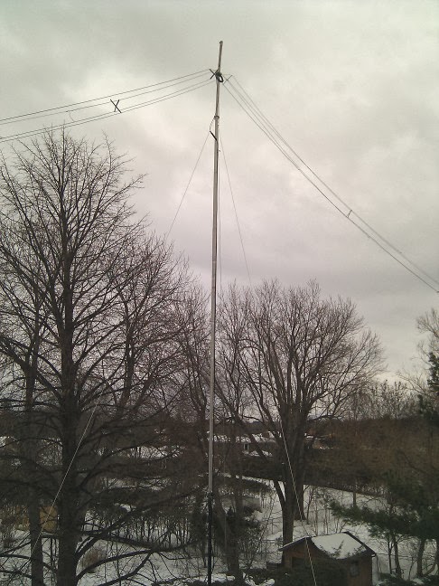
With the recent thaw the rebuilding effort is complete, as the accompanying picture demonstrates. I'll take you through the steps I took.

While waiting for a mid-winter thaw that stubbornly failed to materialize I did what analysis I could of what went wrong and how to rebuild it so that it would last. There were two contributing factor that I was able to determine:
  1. The two sections of 4' nesting army surplus fibreglass mast were not able to withstand the bending stresses to which they were exposed. These were located at the bottom of the mast, nesting within the 6 meters long house-bracketed Schedule 40 steel pipe and supporting the 6 meters aluminum mast (a re-purposed yagi boom). I was attracted to the mast since I had it and it had just the right dimensions to fit the pipe and aluminum mast with a single layer of aluminum shim (roof flashing). In particular, the weak point was the neck of the small-diameter protrusion that nests within another mast section.
  2. The back stay that holds the mast vertical (in opposition to the weight and tension of the raised antenna) is dacron rope. It is more than sufficiently strong in this application. However it does exhibit some stretch even if dacron stretches less than many other rope materials. This made it difficult to reliably set the tension in the stay. Even then the mast would move in the wind, and more in high winds.
The two factors are not independent. As the rope stretched it put more bending force on the mast. The stress would be at its maximum at the bottom where the fibreglass mast nests within the (unyielding) steel pipe. I suspected a problem before the mast failed since some noise came from this area when the wind was gusting. I just didn't realize how serious the problem was going to become.

Version 2.0 of the mast addresses both problems. First, I replaced the fibreglass with an 8' length of 18 gauge galvanized steel fence post. Although I made a modest effort to see what the local stores had in the way of suitable conduit, pipe and fencing steel there was nothing of a size that was a good fit to both the aluminum mast (1.5" OD and 1.375" ID) above and the steel pipe (1.61" ID) below.

For the bottom fit I used several layers of aluminum flashing as a shim to raise the fence post's outer diameter of ~1.4" to be a close but not too snug fit to the pipe. Some play is necessary since it is difficult to insert the mast when you have are holding the entire 8.5 meters length of mast above your head while it wobbles in the wind and balancing on the edge of the roof. Safety lines ensured that I would not be injured but it is still a tricky operation.

I used a circular saw with an abrasion disk to cut two slots at the top end of the fence post. A smaller diameter steel pipe with (more) aluminum shim was placed within the post and then compressed with a muffler clamp. The shim and inner pipe also fit within the aluminum mast for a snug press fit. A steel hose clamp was tightened at the bottom of the mast to strengthen (but not compress) it at this stress point (see below).

All of this fabrication was done indoors, where I was snug and warm. I used a plastic Schedule 40 pipe with the same dimensions as the steel pipe as a proxy for the fitting. The end section of the aluminum mast was brought indoors for the same purpose.

The second problem was simply addressed by replacing the dacron rope stay with ⅛" aircraft cable. Although the cable does not stretch some pre-load is needed to ensure the mast stays vertical when the tension of the antenna pulls the stay taut.

The picture above is not too detailed but hopefully it is clear enough to see the couplings. A close-up of the top of the post is visible in the picture at right.

The clamp at the bottom of the fence post holds the aluminum shim in place and serves as a mechanical stop to ensure the post slides into the pipe the correct distance. In the middle of the post the protrusion you can see in the first pictures is a rope cleat that makes it easy to secure the antenna pulley rope in a couple of seconds. Previously I had to tie the rope to a bracket or clamp. This was too time consuming since the antenna went up and down multiple times to tune the antenna and make mechanical adjustments.

The operation to install the new mast took 3 days. More precisely the elapsed time was 3 days although the work involved was only a couple of hours.
  • Day 1: Shovel the snow off the section of the lower roof where I need to walk and to place the ladder to access the upper roof. I also shoveled what parts of the upper roof that were accessible from the lower roof. The above-freezing temperature did the rest over the next day.
  • Day 2: Assemble the mast in the driveway (it's much too long to fit within the garage), carry it to the site and swing it vertical. Since all the steel is at the bottom the extra weight is not an obstacle to this operation. However it still takes some muscle to flip up a long mast from one end. All the ropes and cables are tied or taped to the mast in the reverse order they will be released once the mast is in place. Go onto the upper roof and do more shovelling of work areas. Wait several hours for the weather to melt the remaining layer of slush and ice. Finally, raise the mast, tension the stay and attach the pulley rope to the antenna (which I left hanging where it was on the roof after cutting it free of the failed mast). Make adjustments to the antenna spreaders that had collapsed during the mast failure and raise the antenna into the air. Connect the coax, cross fingers and load it up. Hey, it still works!
  • Day 3: Clean the rest of the ice off the antenna tie-down ropes and adjust the tension on the stay. Raise the antenna to its full height, tie everything down and seal the coax connections. Get everything done just as the thaw comes to an abrupt and cold end.
When the mast failed 6 weeks ago the bottom section of aluminum tubing ending up with a smooth bend. Try as I might I was unable to straighten it. The aluminum alloy used in antenna masts and booms is very tough stuff. Doing so in any case can be dangerous since aluminum and aluminum alloy can easily fatigue and weaken when trying to undo the first damage. Since it proved so resilient to my repair attempts I decided it is more than strong enough to hold up itself and the antenna, forces which are less than what I subjected it to during my failed repair attempt. The slight hook at the top of the mast looks a bit odd but this is only a cosmetic flaw.

With that major repair operation taken care of I climbed the tower to turn and retighten the TH1vn multi-band dipole to its mast. A couple of strong wind storms spun it so that it favoured the polar paths, but put Europe in its side node.

This spate of mid-winter antenna work should suffice for the rest of the winter, including the upcoming ARRL DX contests.

Sunday, January 12, 2014

Terminator - Android App

Several years ago I found myself writing applications for the Android platform as part of the professional side of my life. My original career path was software development, which I abandoned after several years to switch my career track towards business and management roles in high tech. I reentered the software world with reluctance. But in business you often do things because you have to, not because you want to.

I have several published apps at this time, most of which I wrote either as personal training or out of personal interest. The business apps I wrote are separate from this activity, none of which has been published. Over a year ago I decided to develop an app that I wanted to facilitate my resurgent interest in amateur radio. That application is titled Terminator. Like all my personal apps I published it under the umbrella of one of my businesses: FullQuieting Inc.

After using it myself for many months I decided it was time to make it public. This fall I polished it up and got out the last (I hope) of the bugs and published it on Google Play over the holidays. Since app discovery is a challenge for any smartphone app nowadays I am engaging in some shameless self-promotion in this post. This is only to increase awareness, not enrich myself. The app is free and ad-free, and will stay that way.


The app is not dissimilar to some others, although I haven't seen one for Android with the set of features that appeal to my DX needs. It was also an opportunity to experiment with some heavy duty real-time graphics.

The features of the app that are most oriented toward amateur radio and DXing include:
  • At a glance view of night, day and terminator around the globe. This gives a strong hint of which bands and compass directions to focus on for best results.
  • You can "drag" the shadow to see where the shadow and terminator at any chosen time of day. The reset button at the upper left returns the view to real time.
  • The date up and down buttons (week or month) do the same but for other times of the year. The reset button returns the view to real time.
  • Enable grid squares in the Settings (lower right button). This is used for manual entry of your location, if you like, and will also show the grid when you touch the location icon on the map. You can see where that it is focussed on FN25bi, which is where I am. If you don't know your grid square, the device's GPS is used to find your location, and you can discover your grid square and sub-square.
  • Also in Settings you can set the time format to UTC (z).
  • In the Layers screen (lower left button) you can select a world map labelled with country prefixes. It is best to to set the shadow to "light" so that the map is easily read for areas where it is nighttime.
  • Touch the sun icon to get the sunrise and sunset times for your location. Pressing for ~1 second and the current solar indices and solar image are retrieved. This data -- flux, A, K -- is from the WWV report.
As I said above, I know that this is shameless self-promotion. However, the app is free and ad-free so I am not feeling guilty writing this post. If you like it, use it. One of the challenges of mobile app development is app discovery: there are hundreds of thousands of apps out there so even many good apps are simply not found by people who would like them. If it does get popular I may add more features.

This is my sole attempt at marketing this app. You can find it on Google Play on your Android phone or tablet. Just search for apps by FullQuieting and download.

I'll get back to 40 meter loops in my next article.

Tuesday, January 7, 2014

Chevron Loop for 40 Meters

The delta loop is a popular low band DX antenna with its omnidirectional pattern and low-angle radiation, and requiring only a single high support. That is, when fed for primarily vertical radiation λ/4 from the apex or a bottom corner. That is the antenna I currently use for 40 meters, using a single support up about 15 meters. It works well, or at least as well as it can with QRP (85 DXCC countries in 3 months).

There are other 1λ (full-wave) loop configurations that do equally or better than the delta loop, and also require just the one high support. One of these is what I choose to call the chevron loop since it is in the shape of a chevron. I'll compare the chevron loop to the delta loop and another loop configuration -- diamond square -- for comparison.

First however I'll mention what led me to this antenna. I wanted a loop that, like a delta loop or inverted vee requires one high support. It also had to be a full-wave loop to, I hoped, have gain over a delta loop at low elevation angles. To this end I folded up a loop like a stacked inverted vee to put the bulk of the wire as high as possible. It was then a simple matter of crunching the numbers through EZNEC. Whether a loop of this configuration has been explored by others, or in its vertical polarization feed, I cannot say.

Now on to the modelling and results.

As with other full-wave loops the chevron loop can be fed for vertical or horizontal polarization, or a mix of the two. For horizontal polarization it is fed at either the apex or the secondary apex directly below it. For vertical polarization it is fed at the centre of one of the vertical segments. That feed point isn't all that inconvenient since there are two tie ropes (for the upper and lower horizontal segments, on both sides of the loop) which the coax can use as a messenger cable.

As a horizontal antenna it performs similarly to a inverted vee with the apex somewhat below the true apex. Since this is not what I need for DX performance I will focus on vertical polarization.


The broadside gain of the chevron loop is 1.7 db better than the delta loop (at 10° elevation), where both antennas have the same 15 meters apex height and the interior angle of the chevron's legs is 120°. If the angle is reduced to 90° the gain decreases by -1 db, and so would be only 0.8 db better than the delta loop. That's one disadvantage of the chevron loop, that the large interior angle demands more yard space than the delta loop if it's up high.

The gain does not come for free. The gain off the sides (antenna plane) is reduced by several db in comparison to the delta loop so it is not a truly omnidirectional antenna. It becomes more important to supplement the loop with another antenna to fill this hole in the antenna's azimuth coverage. The vertical pattern is also slightly sharper. This is good for DX and not so good for short path performance. Your operating preference determines whether or not the pattern is a problem.

The loop itself is more complex as well. That, too, is a disadvantage though not one that is too demanding if you can deal with 4 tie points. It is necessary to "spread" each pair of tie points so that the vertical segment is under tension. Both apexes should be offset from a metal tower by at least 1 meter to reduce coupling and therefore affecting tuning and, if the tower is resonant near 7 MHz, the pattern. This latter is a concern with any vertically-polarized loop.

The loop's horizontal extent can be shortened but with a consequent impact on its performance. I won't go into extensive detail in this article except to say that the particular loop geometry is the result of some experimentation with EZNEC to find the shape that is a reasonable compromise between performance and matching difficulty. The chevron loop is more difficult to match than other loops and, as you'll see, has negative side effects.

As designed in EZNEC each horizontal leg of the chevron is 0.2λ and each vertical leg is 0.1λ (4 x 0.2λ + 2 x 0.1λ = 1λ). When built with 12 AWG insulated copper wire the base 0.1λ length is 4.37 meters at 7.050 MHz. Each vertical leg is this base length and each horizontal leg is twice this base length.

Any full-wave loop reduces to a folded dipole as the interior area is reduced to zero. The chevron loop I've designed is halfway there so we do see that impact. In particular, when horizontally polarized the impedance is in the range of 220Ω to 250Ω depending on height and which apex is fed. A folded dipole is nominally 288Ω, an excellent match to 300Ω ladder line.

If you feed a folded dipole at one end you would expect disaster since the long horizontal arms have the same current and opposite phase. It is in effect a shorted open-wire transmission line. The situation is not so simple in the chevron, yet the same effect is present to a degree. Let's look at those currents.

The currents in the horizontal arms cancel to a large degree since the currents are of similar magnitude and opposite phase. The chevron loop for 40 meters with an apex at 15 meters has a feedpoint impedance of 22Ω when fed at the centre of a vertical segment.

Indeed, most of the radiation from this antenna is from those vertical segments and not the rest of the antenna despite containing only 20% of the antenna's wire length. This is also what appears to give the antenna the extra boost in gain. By cancelling the radiation from the horizontal legs the antenna pretty much reduces to two short vertical dipoles spaced 0.35λ with the current high and in-phase right across each of those vertical legs.
It isn't difficult to match this low impedance to 50Ω coax. Perhaps the simplest method is a quarter-wave coaxial transformer made from two parallel lengths of RG-59 or RG-11. A beta match is also a good choice. However the impedance is not the problem with this antenna but rather with what the low impedance implies. All that current cancellation has more serious consequences. Recall that a full-wave loop has an impedance between 150Ω and 200Ω so this is quite the large reduction.


The chevron is a high-Q antenna, which is unlike loops with a more open interior and high feed point impedance. To get the antenna to work well in the CW segment of 40 meters the SWR is above 3 right across the SSB segment. Tuning is also more critical so you'll have to be careful when trimming the antenna to the correct resonance. The mismatch away from resonance is so high that a transmatch would have to be employed since most modern rigs' internal tuners will not be able to deliver a match.

As modelled, the 2:1 SWR bandwidth is 90 kHz. Battling the SWR down to exactly 1.0 at resonance does not improve the bandwidth since the reactance dominates the resistance (Z = R + jX) away from resonance.

A less obvious problem is the I²R losses in the antenna wire. I modelled the antenna with 12 AWG insulated copper wire which results in -0.5 db loss in comparison to lossless conductors. This compares to a negligible loss of -0.05 db for the typical open loop such as the delta or quad. Heavier wire can reduce the loss but after doing some substitution I concluded it was worth neither the expense nor the additional weight.


One remarkable and attractive attribute of the chevron is its performance at low heights. At apex heights below 15 meters it really shines in low-angle radiation in comparison to alternatives (the plot up above has been updated from earlier articles). With an interior angle of 120° the apex can be low as 10 meters (bottom corners are at chest height!) and still do well. This is despite the high ground losses when placed so low.

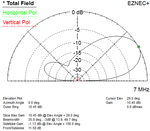
However at greater heights the chevron loop performs poorly at low angles. The reason is that it develops a large high-angle lobe, one that equals the lower lobe when the apex reaches 25 meters. This pattern is shown at right.

Is a chevron loop a good choice for 40 meters DXing? That depends. If you are height limited or at least want to reduce interactions with a high-bands yagi at the top of a tower that is 20 meters tall or less this antenna might suit the bill. I am tempted to make an experiment of it this summer and see if it works as well in the real world as it does in the model. It is not that I doubt EZNEC and its NEC2 core but rather that at lower heights there is greater interference from neighbourhood obstructions and housing metals (wiring, eaves, etc.). Even so the interactions should not be any worse than with my existing delta loop antenna.

I have other loops in the modelling pipeline, some of which I'll discuss in the future. I also intend to build various vertically-polarized loop arrays and compare them to the horizontal wire yagis I recently explored. With the cold wind howling outside it's a pleasure to build antennas on a computer than outdoors.

Friday, January 3, 2014

2013 - The Year at VE3VN

When I ended my 20 year hiatus from amateur radio at the end of 2012 I did so in a very low-impact manner. I had no idea if the rekindling of my interest would be sustained, so I took things one step at a time. There was a necessary expenditure of time and money, in particular the purchase of a new rig (KX3). QRP and minimalist antennas with no permanent structures were my chosen path.

One year later I can say with some confidence that I will stick around for a while. However it is unlikely that I will grow my station to more than 100 watts and, perhaps, a small yagi for the high bands. Even that might not happen in 2014. Other than that my antennas will remain wires. As should be apparent from the dozens of articles I've posted on this blog there will be a continuing interest in antenna experimentation. Some I will build though most will go no further than computer models.

The purpose of this blog is not about ego. Even if no one else reads it a blog is a useful personal diary to document objectives set and met, antenna designs and so forth. Simply put, this is a great way for me to organize an important part of my life as a ham. As long as I continue with the hobby I plan to contribute to this blog. I expect that over time the volume of posts will decline since there is no need to rehash earlier topics (the blog is searchable). There is little incremental value in updates.

There are readers out there. Most of the traffic comes from search engines, from searches on specific antennas and antenna topics. To give you some idea of who comes here the most popular search terms are on the topics of short/small antennas for 40 meters, delta loops and QRP. There are few regular readers.

With that out of the way the following is my summary of 2013:

DX

After my report on the contribution of CQ WW to my 2013 DX totals I worked only a couple of more countries. Both of those were made using techniques I earlier suggested. VQ9 (Chagos) was worked on 17 meters, during the ARRL 10 Meters Contest. All the big guns were contesting, while I was only playing around in the contest. VU7AG (Lakshadweep) was worked about 24 hours before the end of the DXpedition, after most everyone else had worked them. Even so I was surprised to get through.

I therefore end 2013 with 182 countries worked, and 135 confirmed on LoTW. I have at least 100 countries worked on 20, 15 and 10 meters, and I have 80+ countries on each of 40, 30 and 17 meters. Although I have added numerous band-countries in the last month my progress on working new ones was slow, as was my progress on 40 meters. My progress on 30 meters stopped when my multi-band inverted vee came down.

All of these numbers are for 2013 alone. I decided to restart my DXCC count with my return to the air as a measure of what I can accomplish with my present station. My actual totals with my current call are around 325 countries mixed and 300 CW.

Contests

I played around in a few contests this year, primarily out of an interest in adding to my DX totals. That proved successful. What I didn't expect was that contesting would reassert itself as an interest. I only submitted an official entry to 2 contests (CQ WW CW and RAC Winter Contest, in the QRP category) but did make contacts in others on a more casual basis.

QRP

Working QRP is easy. Yes, seriously. All I have to do is call a station and let them do the work of pulling my weak signal out of the noise. While I may get a bit frustrated when I (often) fail to be heard or complete a contact it is not due to the effort expended. My half of the QSO is not difficult; I just transmit, repeatedly, and wait for the other operator to successfully copy my call and report.

There is also no great incentive to call CQ DX since it elicits few QSOs. So even that effort is eliminated.

It does take longer to add up those countries and contest contacts, but not more effort. So, yes, for the QRP operator QRP is easy. Don't let any QRP operator tell you otherwise. Pity the QRO operator instead.

Antennas

The delta loop is working well on 40 meters. However there is only so much it accomplish with 5 or 10 watts. Even so I am approaching the DXCC threshold with 84 countries worked. As readers may have noticed from a number of recent articles I am planning for a more effective antenna on 40 meters.

With the multi-band inverted vee down since the beginning of December my results on 30 meters and up have been lagging. This antenna not only favoured the important east-northeast path to Europe, west Asia and Africa, plus Oceania, its greater apex height helped on long path DX. Apart from being noisy due to proximity to the lighting and electronics of my own house and that of my neighbours it worked really well.

The (so-called) TH1vn dipole for 20, 17, 15 and 10 currently favours north and south due to a wind storm a few weeks back. I decided to leave it there since many of the countries that are now workable with the higher solar flux are on the polar path to east Asia. Although I've heard lots of new ones from that part of the world I have worked little of note. Low height, zero gain and QRP make this difficult path a challenge.

Looking ahead to 2014

Mast repair

December has been very snowy and bitterly cold. It has not been possible to do any work on the roof to replace the broken antenna mast for the multi-band inverted vee. I have completed fabrication of its replacement, replacing all fibreglass with steel parts. If we get a 3-day midwinter thaw I'll be able to (safely) get up on the roof and install the new mast. I would like to get it installed by the end of the month.

Structures

I cannot do much better for antennas with the small tower and mast that I currently use. My options are to replace the small tower with one that is sufficiently robust to support at least a small yagi for the high bands or to install a self-supporting tower with a concrete base. The latter has implications that I am not sure I want to deal with this year. I will need to decide by the spring.

Antennas

With a tower (either of the above options) I will at the least install a rotatable yagi for 20, 17, 15 and 10 meters. A small yagi for 6 would also be nice, which could be cobbled together from the old long-boom yagi I have in the garage. The boom of that antenna is currently the mast for the multi-band inverted vee.

My venerable TH6DXX can serve for 20, 15 and 10, but probably not for a small guyed tower since the wind load of this yagi is only suited for a more robust structure. I might instead design and construct something more modest, which I would do in any case to add 17 meters. The modified driven-element of the TH6DXX which is now the 4-band TH1vn would have to be returned to its original condition for use in the TH6DXX.

Commercial alternatives are plentiful, including the Spiderbeam which is performing well for many people. However I do have concerns with the Spiderbeam's mechanical design that I may discuss in a future article.

With a tower I have more options for the lower bands. A wire yagi and/or a rotatable dipole for 40 meters are high on the priority list. A fixed or rotatable dipole for 30 meters is desirable. Although there are commercial 30/40 rotatable dipoles I might opt for something that I can design and build myself.

For 80 meters I will keep it simple, such as a half-sloper. If the tower is limited to 15 meters height it will have to be loaded in some fashion. For now it will be enough if I can occasionally work DX and make more contacts and multipliers in contests I choose to enter.

Power

I had intended to refurbish my ancient FT-102 as my path to 100 watts. That is still a possibility. However I am leaning more towards purchase of a new rig despite the added expense. I will only buy a rig if I put up a tower. Otherwise I'll keep my station small and learn to live with 10 watts. QRP is more fun than I expected so this is not so terrible a fate.

To more aggressively pursue DX will require more power. There is no kilowatt in my future so 100 watts will be my self-imposed limit. The noisiness of my neighbourhood makes it likely that I would attract stations with a kilowatt that I cannot hear. There is also my unwillingness to deal with the inevitable EMI, just like I had when I ran QRO years ago.

Monday, December 30, 2013

Construction Notes on Those Wire Yagis

In my preceding articles on the design of wire yagis for 40 meters -- dipole elements, inverted vee elements, inward-turning vee (diamond) elements -- I skipped over some important and useful construction details. That was deliberately done so that I could focus on the more important general design and performance aspects of these antennas.

To close out this series I will discuss these omitted topics. For the most parts they are presented as sets of options rather than one strong recommendation. Choose what works for you, provided that you do not take a lazy shortcut that can impact performance. Construction details, although not provided, should be straight-forward for most hams. You should just keep in mind that antenna arrays (2 or more elements) require attention to detail or all the painstaking effort can be for naught. It takes only one small mistake to erase the yagi's performance advantage.

I don't plan on reprising the design notes made in the yagi articles so you should review those (at the above links) as well as the list below.

Switch Box Placement

In the design articles the switch box used to reverse the antenna pattern is placed midway along the boom. That preserves array symmetry and, in most cases, places the switch box at the tower where the boom is likely to be side-mounted. This is an ideal location for robustness, tuning and maintenance.

The switch box itself can be metal or plastic. I've used both in the past. Plastic is probably best since modern plastics are very tough and easy to work with. They also do not interfere with electrical performance of coils and ladder lines.

Relays and Powering

The relays should be low-voltage DC, with internal construction and contacts suited to the power and frequencies. Internal switch box wiring (the schematic from an earlier article is copied at right) and relay construction will add effective length to the ladder lines and tuning stubs so keep that in mind when laying out components.

The relays can be powered via a thin gauge, 2-wire cable or the coax feed line itself. There are many simple designs and commercial products available for the latter choice. If you do use a separate power cable you should employ current chokes in the same manner and locations as the coax. At the very least use a section of cable wound into a choke coil that is effective at 7 MHz.

Boom

Use a plastic or fibreglass non-conductive boom to minimize disruption to the performance of a rotatable high-bands yagi above the 40 meters fixed yagi, and to the ladder line runs from the elements to the switch box. In the past I have used 1.5" (nominal) Schedule 40 ABS pipe for the 6 meters long boom, with a steel or aluminum centre section and a simple rope truss to counter the downward force applied by tension in the wire elements. Only the one truss is needed to stabilize the boom since, with the 2 half elements we have the equivalent of 3-point guying.

If the ladder line passes the metal section of the boom keep the line at least 10 cm away and parallel. It is better to run the ladder line underneath the boom to reduce rain and ice loading and to avoid inadvertent sagging onto the boom.

Reflector and Beta Match Stubs

All of these wire yagis designs employ transmission line stubs to tune the parasitic element (reflector) and drive impedance (beta match). I did this to keep the design and (theoretical) tuning process conceptually straight-forward. This is not necessarily nor always advisable in practice.

There are two significant concerns with using stubs: tuning and interactions. There is no way to tune these stubs except by cutting, adding or replacing. The potential for detrimental interactions comes from the need to put the stubs where they won't coupling to each other, the tower, the boom and anything else nearby.

One popular method (and one that I've used in wire yagis) is to construct a tunable stub as shown in the adjacent diagram. You need to use open wire line with bare inductors. For minimal interaction run these downward, perpendicular to the boom and parallel (but not too close) to the tower. Brace the stubs at the bottom so they don't move in the wind.

A sliding or movable shorting bar tunes the stub. Above the shorting bar the stub adds inductive reactance (shorted stub) and below the bar it adds capacitive reactance (open stub). Make the total stub length about 25% longer than called for in the design and slide the shorting bar during the tuning process to change the net reactance. The shorting bar can be as simple as a short length of wire with two alligator clips. Once tuned it is recommended that this be replaced with a soldered wire.

The stub length should be changed if the open wire line is other than 300Ω. The required length is, roughly, in inverse proportion to the design length, which was based on 300 lineΩ.

Alternatively you can use coils in the place of stubs. These can be put inside the switch box for weather protection. Make these air-core coils of rigid, bare copper with a inductance 25% to 50% greater than required by the design. The stubs in the preceding yagi designs have an inductive reactance of around 1.0 to 1.3 μH, so make the coils 1.5 to 2 μH. The coils should have one end open and have at least 10 turns. Tune the coils by moving the tap point. No matter where within the box you place the coils it is good practice to mount them at right angles to each other to minimize coupling.

Current Choke or Balun

The antenna design is deliberately made symmetric to equalize performance in both directions. Some asymmetries will inevitably creep into the antenna when built, and that can result in current imbalances. Use of a common mode choke -- balun or coax choke -- at or near the switch box limits the impact and also helps to eliminate conducted and induced current on the feed line from disturbing the antenna pattern. The main impact is F/B since it is highly sensitive to current phase and amplitude.

Additional chokes along the feed line can ensure that no resonant section of feed line appears anywhere along its length. With inverted vee elements especially it is likely that there will an opportunity for interactions.

Tuning the Antenna

Now comes the real test: you've built the antenna, raised it into the air and you put RF into it. No matter how careful the design and construction there will be real-world effects that will alter antenna performance. This includes everything from stray inductance within the switch box to ground conductance, metal (house wiring, gutters, etc.) in the vicinity and obstructions of all kinds. In other words, the antenna must be tuned.

Before you proceed to tune the antenna ensure that the wire elements are properly tensioned and in their correct positions. A little extra sage will, at the very least, shift resonance. Yagis and antennas for higher bands on the same tower are far more likely to be affected by the 40 meters yagi rather than the reverse. Therefore for the present objective we can ignore this particular interaction. But be sure to test the high-bands yagi for acceptable performance in all compass directions.

To begin, find the frequency where the SWR is minimum. Don't worry about the exact value for now, provided it isn't extremely high. If the found frequency is farther from the design frequency than you'd like you should calculate the percentage error and trim or add to all four element halves. For example, if an element half is 8.8 meters long and it resonates at 7.1 MHz rather than 7.05 MHz, the element halves should be lengthened by 100 x 50 / 7100 = 0.7%, or 6 cm. Typically you only have to do this trimming once, or twice at worst if you're careful. After trimming check that the SWR minimum is now at the correct frequency.

Next, we proceed to tune yagi gain and F/B. We do this by concentrating our effort on the F/B, not the gain. The gain curve is too flat to allow for accurate peak tuning. The F/B peak is relatively sharp.

Look at a local or great circle map to find the locales that are broadside to the antenna in both directions. If convenient you can use a local ham who is suitably located. Although not equivalent you can get close to correct tuning of the far-field sky wave by using ground wave or space wave. Back in the day (1990) I had a variety of short wave broadcasters to use as test signals. The best was the ideally (though illegally) placed Radio Tirana at 7.065 MHz. Today, alas, those antenna test beacons are gone.

Toggle the direction switch. You should see some difference in performance on test signals. That will confirm that it is (mostly) working as intended. Now take your friend up and down the band (or find other stations on other frequencies) and measure the F/B. Find the approximate frequency where it peaks. If this frequency is incorrect you will need to climb the tower and tune the reflector stub (or coil). Add or subtract inductive reactance to move the gain and F/B peaks down or up in frequency, respectively. Repeat this procedure until you get it right. You can use EZNEC or other software to determine how much to change the reactance to shift the frequency the desired amount.

When the F/B peak is at the correct frequency the peak gain will also be at the correct frequency. But test to be sure the gain and F/B performance are as they should be in both beam directions. If they are not you must have some asymmetry in the construction or with obstructions and conductors in the antenna's near field. Don't obsess over perfection but do address any serious shortcomings.

The last step is to adjust the beta match stub (or coil). You want to find the position where the SWR is 1.0 at the design frequency, which is where you trimmed the antenna for minimum SWR. If the frequency where the SWR is 1.0 has shifted too far you will need to go back and repeat the tuning procedure, starting with trimming the element halves.

Next

That's all I have on 40 meters wire yagis for now. I have other design ideas for 40 meters antennas, both single elements and arrays, that intrigue me with their potential. More on those in 2014.

Happy New Year!

Thursday, December 26, 2013

40 Meters Wire Yagi - Diamond Vee Elements

If you are familiar with Spiderbeam and HexBeam commercial wire yagis for the high bands you will have noticed that they sweep the reflector and director elements inward at the ends. This allows a lightweight design through the use of wires rather than self-supporting tubular elements. The general principle is not new, having first run across it myself 30 years ago in the work by the late Les Moxon, G6XN, in his book HF Antennas for All Locations published in 1982 by the RSGB.

There is a price to be paid with such a design. First, the element interactions can prove problematic. Any metal placed near the end of a dipole will couple strongly and will certainly change element resonance. When that metal is another yagi element the impact is greater, including yagi performance characteristics.

Second, the centres of the parasitic elements must be moved outward to compensate for the folding since the point of average current is located inward. The same thing occurs with an inverted vee antennas and is the major reason why its low-elevation angle gain is less than a dipole whose centre is at the same height. This accounts for the average -1 to -1.5 db gain for the 40 meters yagi I modelled with inverted vee elements versus the one with dipole elements. The average height of the antenna currents in the inverted vee yagi is 1.5 meters lower than the one with dipole elements which at 0.6 db/meter accounts for much of the difference.

The 2-element wire yagi for 40 meters I had in 1990 was of the type with inward-folding inverted vee elements. Although I could not model the antenna back then to explore its performance I was intrigued with the general idea. I folded the elements inward and then tuned the elements to optimize its performance. I did not have someone else's design to work from.

For the present exercise I can use EZNEC to explore this class of wire yagis. My first step was to simply fold inward the inverted vee elements of the yagi described earlier. A new design parameter has also been added: the separation of the elements at their ends. There are a couple of things we should expect to see, even before we jump into the detailed design:
  • The gain and F/B will decline due to the lesser effective boom length. The effective length is approximately determined by the position of the average current; that is, the point on each element half where half the current is inward (and outward) from that point. The approximate value is 30% of the element half length from the element centre.
  • Increased coupling between elements will lower the antenna's resonant frequency. The elements will need to be shortened as the separation of the element ends is reduced.
  • Antenna Q is expected to increase due to stronger element coupling. This should at least impact the SWR bandwidth.
Unlike the previous two yagi designs there are more variables and calculations in the model. The most troublesome is finding the positions of the element ends as the boom, separation, vee angle and wire length are changed. EZNEC's scaling and rotation features are difficult to use, and usually more trouble than they're worth. You almost never get what you actually want. Instead I designed a spreadsheet which takes care of the trigonometry and algebra to get the X, Y and Z values to plug into the EZNEC wires table.


Above is an image of the spreadsheet for this model of the "diamond configuration" yagi. The variables to be entered are in gray/yellow and the wire ends are calculated in a form ready for EZNEC entry. The effective antenna height and boom length are also calculated. Notice that in this configuration the effective boom length has been shortened by more than 1 meter. This will impact yagi performance.

I followed the tuning procedure described in the first article in this series. The performance of the diamond configuration yagi is shown at right, and that of the previously-described inverted vee yagi for easy comparison.
  • Forward gain of 4.5 dbi is 0.7 db lower than at its maximum point in comparison to the inverted vee yagi with parallel elements. There is less gain degradation higher in the band.
  • F/B is degraded by 3 db, peaking at about -14 db. The frequency spread between maximum gain and maximum F/B is unchanged.
Each element half for this yagi is 8.77 meters long. The boom is 6 meters and the element-end separation is 2 meters. The beta match stub is 0.82 meters long and the reflector stub is 1.15 meters long. The direction switching system is as in the first article in this series.
Although the performance loss is small there is still the question of why do this at all? Unlike the case with a commercial rotatable antenna such as the Spiderbeam there would appear to be no good reason to fold in the elements of this fixed wire yagi. I will come back to this, but first let's look at the final performance parameter: SWR.


As expected the 2:1 SWR bandwidth has shrunk to under 100 kHz. To keep the SWR below 2 at 7.000 MHz I had to move the resonant frequency downward by about 20 kHz. As before the antenna is tuned for maximum gain at 7.000 MHz, since this continues to provide the best balance between performance and match for primarily CW operation.

The SWR impact is arguably the only deleterious impact of folding the elements into a diamond shape. Gain and F/B can be largely restored by increasing separation of the element ends, extending the boom, or some combination of both. However, while increasing the boom length can restore the effective boom length to what is was with parallel element the same gain cannot be achieved. In concert with the boom length the ladder line between elements and switch box must be lengthened, and the elements shortened. Shorter elements lower the achievable gain. Aside from matching considerations the gain of a λ/2 dipole is 2.13 dbi, which gradually declines to 0 dbi in the limit of zero length. The same applies to yagi elements.

On the other hand the diamond wire-yagi configuration does have advantages:
  • Fits into smaller lot sizes. By bringing the element ends together to a common tie point it is possible to orient the yagi to a wider ranges of directions. In a long (200') and narrow (50') property like mine I am restricted in the choice of directions which allow tie points for parallel elements. The range can be increased by reducing the inverted vee interior angle, at the cost of lower effective height and poorer performance. While modest, the shorter elements help to fit the antenna to the lot. For longer booms the elements can be even shorter (due to the loading of the longer runs of ladder line to the switch box).
  • There may not be suitable tie points (height and spacing) for all 4 ends of parallel elements that maintain antenna symmetry. Loss of symmetry negatively impacts yagi performance.
  • Symmetry is easy to achieve in this antenna. The diagram at right demonstrates the method of element tying that enforces symmetry for the element to boom angles, inward folding and element separation. Given the lengths of a half element, boom, interior angle and element-end separation the lengths of rope from element end to common junction can be calculated (see adjacent diagram). Grab the common tie rope and you will find there is only one radial line from the tower where the tension equal. Then you only need to tie the common rope at the height specified for the interior angle. The spreadsheet shown above calculates the lengths of the tie ropes and height of the junction per the model.
The design parameters I chose for the diamond configuration I described above are a reasonable compromise between performance and robust construction. I am not posting the EZNEC files and related spreadsheets, however I will happily supply them to anyone that asks. You can then play with them to come up with designs suitable to your individual circumstances.

In a future article, probably the next one, I'll say a little more about construction of the 40 meters wire yagis from this and previous articles.

Tuesday, December 17, 2013

40 Meters Wire Yagi - Inverted Vee Elements

A wire yagi made with dipole elements has the disadvantage of requiring multiple supports. The best arrangement in a two-element yagi is for 5 supports, all at the same height: one for the boom and four for the element ends. While that made the 40 meters yagi in my previous article essentially impractical to build it did serve as a good starting point, with the model allowing the inspection and optimization of performance, impedance matching and electronic direction switching.

The yagi modelled in this article is easier to build since it uses inverted vee elements. It requires only one support -- for the boom. The ends of the antenna are tied to ground supports with the aid of ropes from the element ends to the tie point.

The model is identical to dipole array save for the bending of the elements at their centres. I set the interior angle to 120° and left the element centres at the original height of 20 meters over a medium ground.

Symmetry (as I harped on before) remains critical to array performance. The angles of the elements should be equal -- this is more important than adhering exactly to an angle of 120° -- and remain parallel to each other and orthogonal to the boom. This requires some care in the selection of tie points. It is also important to use high-quality end insulators for the elements, and not simply bind the rope directly to the wire ends. What may be acceptable in a single-element antenna can destroy the performance of an array.

The design itself is quite simple. First I took the (EZNEC modelled) reference dipole from that previous article and bent it into an inverted vee with an interior angle of 120°. The SWR was then swept to find the resonant frequency. Bending the elements in this manner raises the frequency at which the antenna reactance is 0.

The resonant frequency rose by 1.27%. For small percentage changes (under 10%) it is sufficient to simply change the antenna length by the same amount. In this case the legs of the vee were increased by ~1.27% (rounded to the nearest centimeter) which moved the resonant frequency back to where it was for the original dipole.

The purpose of doing this was to avoid a lengthy retuning procedure for the yagi which is complicated by the 3 meters of ladder line running from the switch box to each element. Using an educated guess as to the impact of the fixed ladder line length's on the total element resonance I proceeded to add 1% to each element leg before bending them into inverted vees. Scaling elements in EZNEC is something I prefer to avoid since it can be tricky, or at least finicky.

Here is the SWR sweep that I got from this simple procedure.


If you refer back to the earlier article you'll see that the SWR curve is almost identical. What can I say except that I made a lucky guess.

A match is nice but insufficient. We need to look at the yagi's performance. The questions to be answered are: are the frequencies of maximum gain and F/B in the correct positions, and, how does performance compare to the yagi made from dipole elements?

To make the comparison easy I put the performance plots for the dipole yagi (from the previous article) and the inverted vee yagi next to each other. It should be obvious that the two are very similar, with some important differences.

Please note that all gain and F/B figures are, again, at a 10° elevation angle, not at the angle of maximum radiation. I chose this angle because it is a good median value for DX paths.
  • Despite the same SWR curve the frequencies of maximum gain and F/B are both lower by about 25 kHz.
  • The F/B curve, apart from the frequency shift, is nearly identical.
  • The maximum gain is lower by about -1 db. This is expected. However the gain bandwidth is sharper; gain falls off more quickly at higher frequencies. At 7.2 MHz, for example, the gain is -1.4 db versus the dipole wire yagi. This may be difficult to discern in the chart.
  • The gain versus the reference inverted vee is comparable to the gain of the dipole yagi versus the reference dipole. The reference inverted vee is approximately -1.6 db versus the reference dipole.
The gain differences are largely explainable by the difference in the heights of the current averages for the reference antennas and yagis. There is an exception at the point of maximum gain where the gain of the inverted vee yagi is better than the -1.5 db average by 0.5 db. I don't know the reason for this.

Of course the height of average current is responsible for gain differences at low angles. The elevation angle of maximum gains of the reference dipole and inverted vee at 20 meters apex height are 30° and 32°, respectively. However for the dipole yagi and inverted vee yagi these angles are 28° and 29°, respectively.

The yagi gets its gain by narrowing the main lobe in both azimuth and elevation. Thus a yagi at the same height as a dipole concentrates more of its energy at lower angles. This improves DX (low angle) performance versus non-DX QRM (high angles) in the direction the beam is pointing.

My final act with this model was an attempt to raise the frequencies of maximum gain and F/B back to where I wanted them (the same as the dipole yagi). Although the impact of the 25 kHz lowering of these frequencies is not a serious flaw I am interested in how difficult the tuning would be. I tuned these parameters by shortening the length of the reflector stub by 6 cm, from 1.12 to 1.06 meters.

Unfortunately this changed the (above) ideal SWR curve by shifting the minimum SWR point higher by 20 kHz. The tuning of the reflector changes the array resonance in the same direction. Although minor the SWR at the bottom of the band rose to 2.1, which may be a problem with some transmitters. By adjusting the length of the beta match stub I could shift the resonance almost to where it was before. However, this simple act did not change the SWR at 7.0 MHz.

A full tuning procedure would be require per the step described in the previous article. Since this is not an antenna I plan to build I decided to stop and sidestep the additional work. I have one more variation to apply to this antenna to make it something I would be willing to build. That antenna may be worth the effort of detailed tuning. This will have to wait for future article when I have time to do the modelling work.