Wednesday, May 29, 2013

Choking the End-fed Antenna

In an earlier article I discussed the ramifications of common-mode currents on the coax feeding a nested delta loop antenna. I used EZNEC for that demonstration and also referenced other material. Since my guest room is free once more I decided to deal with a persistent problem I had when I reassembled my temporary station (which took all of 10 minutes).

Unbalanced antennas are very prone to currents on the outside of the coax. This can be used to good effect when making the coax part of the antenna, while at other times it is a pattern-altering, RFI/EMI-inducing nuisance.

Loading the aluminum eaves trough with a tuner is very much an unbalanced antenna system, and there are unwanted currents on the coax. This does not compromise the antenna pattern much, sadly deficient as it is. But since the KX3 is less than 3 meters of coax away from the tuner (antenna feed point) that current does wreak some havoc.

The reaction of the KX3 to the current is quite stark: it aggressively folds back the power. With only 10 to 12 watts available (8 on the highest bands) the power reduction can be a problem. I am ok with QRP but QRPp with this poor excuse for an antenna is more painful than I like. I could only go up to 5 watts on 15 meters and 3 watts on 10 and 6 meters.

I grabbed a 1 meter long RG-58 patch cord from my box of cables and added it in line (with a T-connector, which was the best I had) to add the slack I needed in the transmission line. I then made a coax choke from that slack, which worked out to a 6 turns coil with a diameter of 12 cm. I proceeded to tune and test the altered antenna system on all bands from 20 through 6 meters.

Even with this suboptimal coax choke the results were remarkable. The RFI incursion into the KX3 became negligible. When matched with the tuner, the rig now puts out full power on all bands. Not only that, the KX3 exhibits no audio artifacts on QSK and the SWR behaviour is smooth, not abrupt, when adjusting the tuner. Antenna current now appears to be staying where I want it, on the wire counterpoise and antenna proper.

The lesson here is that perfection is a laudable objective, but don't let that stop you from trying something of lesser quality. Experiments like this are cheap and can have a large benefit. Coax chokes are not ideal since they are reactive and therefore cannot cover all the HF bands. However they can work well. If one doesn't it's easy to add or subtract a few turns. There really is no excuse not to have a choke on your coax transmission lines.

In the interaction article I pointed to a comprehensive discussion on the choking of common-mode currents on transmission lines by K9YC. There are examples in there that are quite good (high resistance), but that require ferrite cores. I will now point you to some air core alternatives, with test data, made by G3TXQ.

Monday, May 27, 2013

Scoring a Second-hand Tower

In an earlier article I described my antenna siting options. Three of those options (and two that I plan to use) require a small tower: one bracketed to the south side of the house (B) and one guyed in the yard (C). The missing piece in my expansive junk box was the tower itself.

It seems that even buying a new tower is not the easiest of propositions. Finding local dealers and arranging transport are neither easy nor inexpensive, yet my requirements are modest. A tower of 30' or so suits my antenna objectives. Additional height would come from a mast to support the apex of wire antennas.

The industry has changed in the 20 years I've been out of the hobby. There were 2 major domestic manufacturers of residential-grade antenna towers: Delhi and Trylon. While Delhi is no longer in existence, its tower business now belongs to Wade Communications. Trylon is still Trylon. Common US tower brands such as Rohn are not often seen in Canada since towers do not travel well. By this I mean that transport is expensive (due to size and weight) and not always easy to arrange, and domestic dealers are few.

The Delhi towers are the DMX series that are ubiquitous in the backyards of Canadian hams and the lighter-duty Golden Nugget series that are typically used to support TV antennas. Both lines appear unchanged and are on offer from Wade. After a brief and fruitless search Wade pointed me to a local dealer. But then I went online to first look for used towers.

Finding used TV towers was becoming difficult around 1990 since the migration to cable was largely complete. Except in rural areas there were few used TV towers for the taking. The market has since reversed course due to the resurgence of OTA (over-the-air) TV viewing by so-called "cord cutters". Used Golden Nugget towers are showing up everywhere.

I now have a 30' Golden Nugget 18-gauge tower (actually about 28.5' when built) sitting on my deck, including a 10' length of 1.5"-OD mast. It was free for the taking, provided of course the purchaser took care of taking it down. So I dusted off (and tested!) my climbing gear and quickly relieved the homeowner of it. I left him the TV antenna and rotator so that he could sell it, and so come out ahead as well.

These towers are relatively easy to put up and take down if you have experience with the bigger, amateur-grade towers. I easily handled it on my own, with the homeowner as ground crew. I did make a sight on the drive across town with the tower dangling out the back of my sports car.

You do get some surprises when you see how some of these TV towers are installed. It's a bit scary what passes for a residential tower installation. I'm sure the reason the majority of these towers don't come crashing down is because the bottom 2/3 is sheltered from the wind by the house it's bracketed onto.

There are always going to be trade offs when you go the used route rather than buying new equipment. Towers are no different. A compromised tower is not one that should be repaired; it should be thrown out!

Rust is common. Galvanizing is not a miracle cure, it only delays the inevitable. Cheaper tower uses the cheaper galvanizing process of electroplating rather than the better hot dipping. This tower appears to fit into the former category. Apart from cosmetic rust there is more serious deterioration at the bottom of the bottom section and the base plate since the previous owner buried the bottom with the intention of making the installation more sturdy. That is unnecessary when properly mounted. Burial greatly reduces the life of any tower, especially those with tubular legs since water will pool inside the leg.

You can get an idea of the rust in the close-up view I've attached. Although the base plate looks quite bad it is in fact perfectly usable; most of the "scale" you can see is debris that can be cleaned off. The base metal is mostly intact though little of the zinc coating remains. The base plate is heavier gauge steel so that it can withstand ground contact for the life of the tower.

Of more concern is the bottom of the tower. Golden Nugget is 12"-face, 18-gauge steel (I weighed a 10'-section a 12.1 kg, or 26.5 lb) and is vulnerable to weakening due to rust penetration. The tower also comes in 16-gauge steel, but you don't usually get to choose when you buy used. I doubt that most OTA users are aware of the difference and simply steer toward the lower-price option.

On first inspection the tower bottom looks good enough for reuse. The rust scale will have to be removed and then painted over with a suitable product. Even so I am reluctant to use this tower at site B, bracketed to the house. It may be best suited at site C where it can support a fibreglass mast and wires for the low bands, in particular a delta loop for 40 meters.

The other thing I've collected recently is stackable 4'-sections of 1.75"-OD surplus fibreglass mast from Maple Leaf Communications. The price was right and it looks as if it can do the job I require of it (without actual specs there is some risk which I will mitigate as well as I can). As I pointed out in the article on the nested 20-15-10 delta loop antenna, the mast must be non-conductive and would have to vertically span 7 meters. I bought enough of the fibreglass for both this antenna and for the top part of the supporting mast of the 40 meters loop.

I'll have more later when I am ready to erect antennas. I still have a little more work to do to prepare the basement shack, work that is harder for me to get motivated to complete as the season grows warmer. For now I am QRT since I ran into the foreseeable problem of setting up in the guest bedroom: guests arrived.

Saturday, May 18, 2013

QRP Antenna Tuners

In my junk box I have a few antenna tuners, small and large. There is also a selection of components that can be cobbled together to make more should I be so inclined. One of those commercial products was put to work in my current station to coerce my eaves trough into an impedance that my KX3 will (mostly) tolerate.

The one I chose is a small L-network tuner by MFJ that is suitable to end-fed wires. Other network topologies would also work, but I chose this one because it is small enough to comfortably (and unobtrusively) sit on the narrow window sill just under the wire coming in from its attachment point to the eaves trough.

The thing is, aesthetics aside, was this the proper choice for my QRP station? Consider the two (very dusty) tuners in the picture below, both of which I dug up from my basement horde of ham paraphernalia. If you had to choose, which do you think is the best antenna tuner for QRP? (For the moment please ignore the fact that these are very different tuner circuits, one being an L-network and the other a general-purpose transmatch.)


Have you picked one? The thing is both are correct, under the right conditions. It all has to do with why one uses QRP and one's personal circumstances.

Apart from the obvious size difference there are others.
  • Price - Price tends to rise in proportion to size and features. For example, a little coil is much cheaper than a big coil, a built-in SWR bridge costs extra, and increased size and weight mean higher costs of transport and inventory for the retail supply chain. Buying used equipment can change the equation, as will the price sensitivity of the buyer.
  • Power - When properly designed bigger components means a higher maximum power and mismatch tolerance. While this is not relevant to QRP, the operator may have aspirations for QRO in the future and so may wish to plan ahead.
  • Performance - As a general rule, the greater the mismatch the greater the losses within the tuner. Even if you find that perfect 50+j0 match to satisfy your finicky transmitter it may be that 9 or more of your precious 10 watts are spent heating the shack (and the tuner). This is not an exaggeration. It often occurs with small tuners driving non-resonant antennas.
For the QRP operator who does it under the principle that "small is beautiful" the choice is clear: pick the smaller, cheaper alternative, even if it entails reduced performance. If that is not your style you will need to review your options.

My choice was not based on price or principle. I simplify opened boxes until I found some tuners and proceeded to pick one that met my immediate needs. That was one suited to an end-fed antenna (the eaves trough) and would be easy to get close to the feed point. There was just the one that fit on the window sill. That it is the "best" tuner configuration for the antenna was a bonus, not mandatory.

The price I pay is performance. In practice it is a high price on several bands, particularly on 160, 80, 10 and especially on 15 and 6 meters. This is unsurprising since tuners, and most especially the small ones, get terribly inefficient at their range extremes, in regards to both frequency and mismatch. If you happen to read QST you should pay attention to these measurements in their tuner reviews so that you'll see how true this is.

I did not bother to open either unit to take pictures of their insides. However I'm sure you can guess the difference in coil wire gauge and capacitor plate area. Unlike with a kilowatt, even if every one of my 10 watts is dissipated by the tuner there will be no meltdown. Nevertheless the losses are there just the same. If the tuner has a 3 db loss (500 watts out of a kilowatt) it will also be 3 db with QRP (5 out of 10 watts).

The losses are due to resistances in the coils and capacitors, and core heating of any toroidal transformers. Ohm's Law tell us what we need to know:

P = I²R

For variable coils the resistance increases as the length of wire in the active section of the coil increases and as the wire gauge decreases. For variable capacitors the resistance increases as the plate overlap decreases or the plates are smaller to begin with (less surface area). We typically use more of the coil as the frequency decreases (A moves to the left in the diagram) and less of the capacitor plate area as frequency increases. That helps explain where much of the losses occur on the lowest and highest bands, respectively.

Current compounds the losses. Inside a matching network -- whether in the transmitter, tuner or antenna -- the currents circulating through the components are often higher (sometimes much higher) than the current in a perfectly matched antenna system:

I² = P / 50

This is why the best (and most expensive) components have large surface areas, and those surfaces are silver-plated. For a fixed R the loss increases in a component by 6 db for a doubling of the current. The square of the current quickly rises as the mismatch between the transmitter and antenna system grows.

I would be better served by the larger antenna tuner in my present situation even though it can be tricky getting it to match an end-fed antenna. There is no QRP "aesthetic" standing in my way. It's just that it too big to place near the antenna and it takes longer to change bands since the roller inductor takes more time to adjust than a tapped inductor. Speed and annoyance matter.

For an outrageous example of how inefficient the little tuner can be I tried to use it on 6 meters. To be fair this is well outside its design range. I just had to make the attempt when I noticed a sporadic-E opening one evening. I heard many stations but not one of them heard my 3 watts -- the most power I could coax out of the KX3 into a poor match. When I bypassed the tuner the band noise and received signal strength rose at least 10 db. The SWR was a high though usable 2:1. This time I did log a few stations.

What the actual loss of the tuner was I don't know since I can't easily measure it. I expect that the results on the other problematic bands (mentioned above) are of lesser degree though still significant. It's a handicap to add to my other handicaps of QRP and poor antenna, though a necessary one.

I do enjoy a challenge but this is ridiculous. Should I require a tuner when I get some real antennas erected it will be a big one.

Sunday, May 12, 2013

Interactions

Antennas interact with their environment. In one sense that is obvious since that is the essence of what an antenna is all about: electromagnetic coupling to free space. That is a "good" interaction. There are also "bad" interactions. By this I mean interactions that cause unwanted effects (EMI, coupling, etc.) that degrade antenna performance from the objectives set out in its design.

Many hams are often unaware of or outright ignore interactions. Once the first QSO is made with a new antenna all thoughts turn to operating and away from the antenna itself. This isn't surprising. While we like to promote our hobby as one promoting technology and technological expertise we know that we are in it for the operating. The technology, antennas included, are a part of the journey, not the destination.

As you might guess since I am writing this article is that there is good reason to stop for a moment and consider the antenna's interactions during its design and siting. It can prevent many problems and achieve better performance.

What I will do here is talk about some of those interactions in regard to the nested 20, 15 and 10 meters delta loops antenna I described recently. In the following model the antenna is mounted on a mast at the apex of my roof, which is site 'A' described in the site planning article written earlier. Although, as I said in that article, I rejected that location I am being lazy and using an interaction model I had already created for that site.

The antenna view at right includes a model of a coaxial transmission line, consisting of wires 10 through 12. It is approximately to scale but I made only a modest attempt to be precise about direction and length. My purpose was to get a sense of the interactions rather than to make the coax part of the formal model. You'll have to imagine an outline of my house to see that wire 10 angles down to the edge of the roof (tied to the eaves trough that is my no-antenna antenna). The same goes for the remaining wires, with 11 dropping down to the back edge of the lower roof, and 12 takes us down to near ground level, close to where it will enter the basement.

Two more things about the model: there is only one coax drawn but there will in fact be two, one for the 20 and 15 loops; and, the top of wire 10 ends between the two feed point (V1 and V2) and is connected to nothing. This is obviously simplified though sufficient for our purposes here. By not connecting the coax to the antenna I am modelling the presence of a high-resistance common-mode (current) choke on the coax. This ensures the coupling to the coax is by mutual conductance only, and not direct conductance.

Using a high-resistance choke is important to avoid turning the coax into part of the antenna, with a negative consequence on pattern and match, among other difficulties. Mutual inductance is bad enough, so don't make it worse. I won't get into chokes here, so instead I will refer you to a truly excellent document on the topic by K9YC (PDF). If you have May 2013 QST you'll notice this work referenced in the article on making a common mode choke.


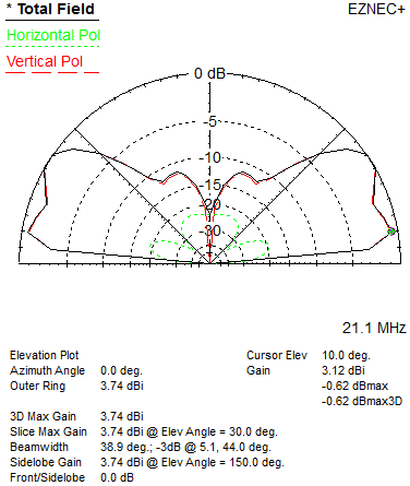
Notice in the antenna view I am showing the plot of currents when fed at 21.1 MHz. This is the worst case scenario for induced currents on the model coax. The currents are much lower on 10 and 20 meters, with lesser impact on the antenna performance.

The currents, especially on wires 10 and 12, are enough to cause a significant change to the far field plots I presented in the antenna article, where I modelled none of the environment. The coupling occurs even though I kept wire 10 nearly perpendicular to the antenna plane. I did not model the aluminum eaves troughing or the house wiring in the 2nd-floor ceiling, all of which are in play when it comes to interactions.

Compare the far field plots shown here for 21.1 MHz to those in the earlier article. It is no surprise that the pattern is no longer symmetrical. The major changes are in the azimuth omnidirectionality and the increase in the amount of horizontally-polarized radiation. The SWR is not shown since it isn't much different, and is besides easily remedied during tuning when the elements are adjusted after installation on the mast.

Are these interactions bad? That depends on your objectives. The increase in azimuth asymmetry (~5 db rather than 3 db) will be noticable though probably not by much in actual use. The elevation pattern, while lopsided, is not too far off the ideal model.

An antenna like this is bound to have unwanted interactions of this sort since it is dimensionally large and close to the house, including all of its many embedded conductors. The difficulties are less for a yagi atop a tower where the coax (and tower) are orthogonal to the antenna plane. Less, but still there. Chokes will at the very least protect loss of depth in the front-to-back and front-to-side nulls.

These are not the only reasons to assess whether the interactions are acceptable. There are others that give me pause and that is why I am still thinking about whether I should build an antenna that is otherwise suitable for my purposes.

Coax currents are reciprocal as they are in any antenna: they act the same on receive as on transmit. With the antenna so close to the house (and neighbouring houses) there are interactions that could be more serious than on the far field pattern or the match.

First, there is the obvious matter of EMI. Using QRP as I am at present the risk is low. That will change should I increase power to 100 watts. With a low antenna where the main field intersects houses that is already a problem. Add in radiation from the coax and the probability of EMI increases. In the above model there are radiating surfaces all the way down to ground level, adjacent to inhabited areas. While a tower and yagi might appear more problematic to neighbours, the EMI risk is often greater from low antennas and all transmission lines.

On receive there is also risk of EMI to us. Our homes are filled with computers and computer-driven phones and other appliances, switching supplies in wall warts and light fixtures, and more. Their radiation will make its way into our sensitive HF receivers via the exterior of the coax. With an eaves trough for an antenna I currently have this problem in spades. In my house I have at least 3 Ethernet-based devices within a few meters of the eaves trough and there are more further away, including my next-door neighbours. If the coax radiates, even if its current is a tenth of what is on the antenna proper, the noise becomes a problem on at least parts of the HF bands. It is easier to install a choke one run of coax than to choke ten appliances.

Yet even with the common-mode choke at the antenna feed point there can still be radiation on the coax, as I've already demonstrated. If it is necessary to go further to solve problems we will have to install one or two more chokes along the length of coax, ensuring that the length of coax between chokes is non-resonant on all bands of interest. If you concurrently operate on more than one radio or band this will include radiation from antennas for those other bands since they will happily couple to coax runs of other antennas.

Many hams do not realize the true source of EMI problem, often blaming it on high power or just bad luck. Yet it can often be cured or at least reduced with more and better common-mode chokes on their runs of coax. Ignorance is not bliss. Just because one is unaware of the root cause of EMI, or poor antenna performance, it will not go away.

Interactions between antennas and all conductors in the vicinity is an unavoidable consequence of the laws of physics. We can ignore those interactions but they will not ignore us.

Sunday, May 5, 2013

Nested Delta Loops for 20, 15 and 10

I am finally getting around to this post. Because of my antenna siting criteria there was, and is, some doubt that I'll put up the antenna described in this article. Regardless of what happens I would like to document the design. Later I will come back to my evolving antenna options, and where this design stands. There are a few interesting ideas in here that may be of value to others in their own antenna designs.

As should be obvious from my previous writing I do have some love for delta loops. Although they are big and (to some) ugly they do have certain advantages:
  • Inexpensive - lots of performance per dollar
  • Multiband - on harmonics
  • Easily configurable for any linear polarization - vertical, horizontal or in between
  • Can be matched to typical transmission lines with a quarter-wave transformer - doing this does unfortunately remove the multiband capability
  • Omnidirectional when configured for vertical polarization
  • Like any full vertical (dipole or loop) it is a decent DX performer even at low heights
  • Requires only one support mast, although it should be non-conducting if vertically-polarized
  • Broadband - low SWR across the band when matched to 1.0 SWR at resonance
  • Loops are quieter in rain, snow and low humidity since there is no corona effect off the ends
There are of course disadvantages, including:
  • If visible to non-ham neighbours it is often perceived as an eyesore
  • There are ropes going everywhere, both to hold the shape of the loop and to guy it and its mast
  • Heavily dependent on ground quality when vertically-polarized (as for any vertical) for far-field performance
  • Can be fragile if not well designed and constructed
For this article let's put all this aside and just design the thing. No one has to use it after all, and that includes me.

From the adjacent EZNEC antenna view it is a somewhat unusual looking design. There are nested loops cut for 20, 15 and 10 meters.

You'll see that there are two feed points: one each on the 15 and 20 loops. They are fed with 70Ω λ/4 transformers (RG-6/59/11) to match the high loop impedance to 50Ω. There is no feedline to the 10 meters loop since it will be parasitically fed. I'll come to that in a moment.

If you're familiar with quad beams you'll likely know that they are fed at a common point, where the loops for each of the driven elements are brought together. This work since the impedance of a quad beam is typically very close to a 50Ω match. That doesn't work in the present case since this is not a beam and matching is required. I did try various techniques but none worked well. Since I am pretty much swimming in coax I decided to go with more than one transmission line.


I mentioned how 20 and 15 are matched, but 10 is special. The 20 loop resonates harmonically on 10 but not where we want it. It resonates well below the band. Also, that λ/4 transformer for 20 is now a λ/2 on 10. What this does is leave the impedance unchanged; it is equivalent to making a full circle on a Smith chart. That isn't what we want.

So what I did was, in effect, make this a 2-element parasitic array on 10 meters, tuning the inner loop such that the array resonates where I want it. This has several affects: the impedance drops to near 50Ω at resonance (which the 20 meters transformer leaves alone); the pattern gets more complex, but does not become a unidirectional beam; and, the bandwidth is reduced due to the increased Q.

As usual I cut my antennas for CW. I also have no interest in 10 meters above about 28.6 MHz. You can adjust the antenna to your operating preferences.

The 20 and 15 loops are fed 1/4λ from the apex (~25% of leg length from the bottom) to make the antennas vertically-polarized and omnidirectional (within 3 db). Although this is covered in an earlier article, the elevation pattern for 20 meters is posted here. Although ground loss is ~3.5 db the gain at 10° is an impressive 1.5 dbi. That isn't possible for a dipole at the same height over suburban ground.

The pattern for 15 is similar. Ground loss drops to 2.8 db and the 10° gain rises to 3.1 dbi. This is quite good.

The actual maximum gain for both 20 and 15 are in higher angle lobes. This makes the antenna usual for domestic contacts, which in my case would only matter during contests if at all. Unlike a low dipole there is a deep null at high angles. This is not too interesting on the high HF bands but it may help remove some domestic QRM while chasing DX.

For purposes of SWR and pattern the ground is modelled on the poor side of medium, typical of suburban areas. The antenna (bottom of the 20 loop) is set at 10 meters. This would put the apex at 16.3 meters. If I build it I will drop it a bit to keep it under the 15 meter height threshold that requires undesirable city (Ottawa) policy conformance.

The pattern on 10 meters is not ideal due to being both parasitic and having one element 2λ long. Of course there is additional gain in some directions, but also less in others. The antenna is fixed so I would just have to live with it as is. I am not too concerned since 10 will soon (2014) begin to decline in importance as the current solar cycle declines. It's a compromise. I could always fill the "gaps" with another antenna.

The surprising thing about the elevation pattern on 10 is that it is horizontal off the ends (antenna plane). That's the effect of driving it from the 20 loop. Even so it does well at low angles, equalling the gain on 15. The high angle radiation is less useful for DX but will come in handy for aurora and sporadic-E openings. Ground loss is a little over 1 db, which is negligible.

The antenna is not omnidirectional on 10. Unlike 20 and 15, at most elevation angles the gain is higher off the ends than broadside. The pattern shown here is for 10°, which is most pertinent for DX. The differential between the gain off the ends and broadside is larger at higher angles. Although this isn't perfectly aligned with my design objectives the compromise is acceptable.

Some construction details follow.

The loops do not have to be perfectly concentric but should not snuggle up to each other. I confirmed this to some extent through modelling, but it is a lot of work to be comprehensive and certain. Therefore it is better to err on the side of making the loops close to concentric. As shown here the separation between the 20 and 15 loops is 141 and 70 cm at the apex and bottom, respectively. Between the 15 and 10 loops the separation is 61 and 40 cm at the apex and bottom, respectively.

The antenna is cut for CW so the SWR climbs towards the high end of the bands, particularly on 10. The model wire is 12 AWG THHN copper. Increasing the gauge to 10 is a good idea for a 40 meters loop, but 12 should be ok here. The bottom of the outer loop in the model is wire, however I would build it using aluminum tubing of about 25 mm diameter (1-inch). I have this already so the cost of aluminum tubing is not relevant. The tube will lower the total 20 meters element length a small amount.

Element lengths are as follows, with 1/3 of the total in each of the 3 sides (equilateral triangle):
  • 20 meters: 21.78 m
  • 15 meters: 14.47 m
  • 10 meters: 10.98 m
Use of a bottom tube avoids the need to guy the antenna to support its shape. The inner loops can be tied down to the same tube. The 20 loop can be tuned by changing the attachment points of the vertical legs on the bottom tube. Remember to tune the 20 meters loop first before tuning it on 10. Apart from this you'll find that the antennas don't interact much (confirmed in the model) so tuning interaction shouldn't be a problem.

Although the interior angles don't have to be exactly 60°, staying close (equal side lengths) will keep the performance in line with the design. Just ensure there is tension on the wires so they don't sag, even under temperature changes (metal shrinks or expands in accord with the temperature) and ice and snow loads.

The apex of each loop is tied to the mast, which must be non-conducting. Fibreglass is a good choice since the antenna stands fairly tall and must be tough to survive the weather, and it can be guyed. When mounted at some height a metal mast or tower can be used under the fibreglass mast provided it doesn't get close to the antenna bottom centre, since it is a high-impedance point. Keep the separation at least 1/2 meter.

Sunday, April 28, 2013

No-antenna DXCC

Since I returned to the air at the end of December 2012 I have been using QRP with a newly-purchased and assembled KX3. My antenna is not a real antenna, just an L-network tuner connected to the aluminum eaves trough (you might call it a rain gutter) on my 2-story house. The neighbours might notice a wire running the 1 meter from around the upper-floor window casement to the eaves trough, if they look very very carefully. This is a stealth antenna on steroids.

With my primary interest in DX it was only natural that I'd try to work some despite knowing that it would be difficult. Doable but difficult. Apart from one VE and several W/K stations all my contacts have been DX.

As I continued my casual operating with this minimalist station the countries slowly added up. As the total grew I began to wonder if I could reach 100, the threshold for DXCC. I was not obsessed by the idea, only curious if I could do it, at least before the warm weather arrived and I could proceed with building a real antenna. By "real" I mean an arrangement of conductors designed to effectively work as an antenna rather than a random conductor co-opted and coerced into behaving as one.

I am happy (and exhausted) to report that I have done it. Last week I logged country number 100 -- OA -- and so I have tentatively qualified for DXCC, assuming I actually go ahead and make an application using these criteria (NB: my actual total is over 300), which is not in my plans. It's enough to know I've done it. This goes to show that with a little perseverance, and luck, just how attainable DXCC can be. If I can do it in 4 months with QRP and a no-antenna antenna pretty much anyone can do so.

My most productive band was 20, closely followed by 30 and 15. Both 10 and 40 were well behind. The main reasons 10 was poor were the lower availability of openings and the need for a really low radiation angle. I also suspect, like many tuners, my little MFJ L-network is consuming most of the power, and on 10 meters that was usually 3 watts. Any more and the KX3 folded back due to the excessive RF getting into all the cables. It's due to pretty much having my temporary shack inside the antenna.During periods when conditions were poor (geomagnetic disturbance) I could work almost nothing.

Apart from the early days, the countries did not come easy. There were ample "VE3?" queries from some rare and not-so-rare DX that never did make it into the log. There were a few good catches, including: J5, A7, XT, RI (South Shetland). There are many more common ones I did not log, and these included KL7, ZL and JA. Then there are the frustratingly loud ones that never hear me, such as D3, 5N, and 5U. I did once get a "VE3?" from the D3. Most DXpeditions were out of the question since only rarely can I get through when even so much as one other station is calling. Pile-ups are a no-go. Yet I did occasionally try, sometimes for the practice and sometimes hoping to get lucky.

All 100 contacts were on CW. I did make a few SSB DX contacts. The wider bandwidth (and therefore 8 to 10 db lower SNR) was not friendly to my puny signal.

With this small victory I can proceed with a lighter heart to construct a proper station, including a room dedicated to the shack and actual antennas. My real objective in this DXCC pursuit had been whether the rekindling of my interest in hamming would last. It has.

How speedily station construction will go I am not sure since like for many hams the radio is more of a winter pursuit. Summer is for antenna raising and maintenance, but mostly for non-radio activities. As things stand, the new shack is drywalled and ready for painting. I have enough material on hand to put up simple masts and antennas. If I can pick up a few tower sections to ease construction and maintenance of suitable supports I will do so. One way or another I plan to be fully equipped by the fall.

I may stick with QRP for a while yet. At least it won't be so painful with a real antenna.

Tuesday, April 23, 2013

Basic Site Planning

I have slowed my antenna design plans a little, which is why I've had less to say on the topic recently. The reason is that I am somewhat constrained with what I will use to mount the antenna. Well, not only that but also a variety of related tasks such as building my new shack and dealing with non-radio matters.

The shack-building has gone slow because of the warming weather. I'd rather be outdoors than mucking with drywall in the basement. However I must finish that space since I need to move out of the spare upstairs bedroom. I also have no intention of broaching the walls on the second floor to bring in coax. On the plus side the basement area I'm using was designed for a shack from the start, including a couple of 240 VAC outlets for the amplifiers I no longer have nor intend to buy.

Getting back to mounted antennas at some height, my plans have changed. I was never comfortable with the idea of using the roof as a support -- although it is a good spot -- because it's simply too visible (see picture in this post). There might also be some friction with the city for much the same reason. The policy on this matter was new to me since I've been out of the loop for so many years.

Since I also have no intention of installing a tower (at least not for the foreseeable future) my options are more constrained. The diagram below shows my major options.


The drawing is not to scale or accurate (my house has a more complicated layout). It is only intended to show relevant structures in approximate positions. The direction we're looking is west.

Option A is rejected, as I've said. In addition to the visibility issue, especially if I put up delta loops, there is a lesser concern with guying the mast. I do have a plan for that which would suffice nicely for a fibreglass mast plus wire loop, since the wind load would be low. However a yagi is out of the question! I am more concerned that the structure would appear fragile to others even if it is in fact very robust.

Option B is my second choice for where to mount the antennas for 20, 15 and 10 (and maybe 17) meters. This would be either a mast or short "TV" type tower secured to the house below the roof line and anchored to the ground without using any concrete. The antennas themselves would stand clear of the roof although the bottom of any delta loop would be below the roof apex. The eaves are about 6 meters above grade and the roof apex is about 8 meters. The roof pitch is not nearly as steep as shown. The aluminum eaves trough that runs along the south roof line is my present antenna.

There are important considerations when it comes to attached a mast or tower to a building. I do know how I would go about it but will not get into that here. It would make a good subject for a future post. One advantage I have is that my house was custom built so I not only know the structural details, I also have many photographs of the raw frame that I took during construction, including the exact spots where the brackets would be placed.

The base and bracket position has been selected so that the mast/tower does not block any windows (important!). The base will be close to the basement shack. I have a spot selected to open the wall to install a conduit for the coax cables that is convenient, secure and out of the way of accidental encounters.

Options C and D are for masts, or short towers plus masts for 40 and 30 meters. Since I concluded earlier that I am favouring delta loops which come close to the ground (~3 meters up) their supports must be placed in the away from the house and deck. My property is deep (200') but relatively narrow (50'). Fortunately it is long in the north-south direction (350°-170°) so it is easy enough to position a loop broadside to Europe. I did this very thing in the 1980s.

What has changed is the vegetation. I drew the two trees nearest to the C and D to their approximately correct heights. Both were much shorter in 1992. Even though both were decapitated in the 1998 ice storm they have since grown well past those heights. Neither is robust enough to support an antenna but the lower trunks are ideal supports for guy lines. They are each close to the property edges (east and west sides) and almost exactly opposite each other. The space in between is a septic field, which is not the place for a tower base. My old tower was close to D so even the concrete had to be broken out of the bedrock to meet DOE regulations for the new septic system.

Option C would place the north end of the delta loops somewhat close to the house but still well out of the reach of eager fingers. The guy line for the south end of the loop would go a tree or something else farther to the south.

Option D places the loops further away from the house, which is desirable. The problem is that there are two other, larger trees to the south of D (not shown in the diagram). Their trunks are just outside my property lines and they branch out over my property so that they nearly touch at a height of about 10 meters. The squirrels love the arrangement (which didn't exist 20 years ago), using it to practice their acrobatics as they bravely jump the space from one flimsy outer branch to another. They almost always make it.

For a ham these trees are a problem. They are large and old, regularly shedding debris that would surely impact any delta loop or inverted vee that dared to traverse that space. There is also a real risk that one of the trees will come down in future years. Option D is out.

So that's the tentative plan: high band antennas at B and low band antennas at C. The choice for high band antennas is still in flux for a variety of reasons. I'll get to those reasons in a coming post. Regardless of how it goes I will make sure to write about the 20-15-10 delta loop array I've designed. I just don't yet know if I'll build it.

Wednesday, April 17, 2013

Power and Contests

You notice some strange things when you have a puny station as It is not easy to be heard with 10 watts and an eaves trough as a poor excuse for an antenna . Even hearing DX is often a challenge on the high bands.

There are two edge cases I've noticed with this station. One is the DX contest stations that are practically beacons on the bands, day in and day out, irrespective of contests. While I don't know any particulars, many seem to rotate operators into this contest mode of operation as a form of training. They sit on a frequency calling CQ and working any and all callers for hours on end. These are undoubtedly superior stations with excellent antenna systems and high power (QRO).

The antenna systems are easy to guess at since these stations are getting through when others in their areas are far weaker on this end of the path. While I can be less sure of the power they are running it is surely a long, long way from QRP. A strong bit of evidence is that even when quite strong here most of these stations do not hear me when I call. Antennas are reciprocal but power is not.

The second case is the weak DX station. My gut reaction is to simply pass them by, reasoning that if I can barely hear them they will surely never hear me. I've proved this many times by tossing in a call and hearing them simply resend their CQ. Not always: sometimes they do hear me and I log a new one. A recent surprise of this sort was working a ZA last week on 20 meters.

It is likely that the ones that do hear me are either running QRP like me, resulting in reciprocity of results, or they have a lower level of noise than I do here. You simply never know. It costs little to make one call and if the weak DX doesn't come back to me or anyone else to just keep spinning the dial. Sometimes I try a few tricks before giving up.

Which brings me back to power and its purpose. Those stations with the big antennas and perhaps even bigger power may seem a bit overindulgent. It is reasonable to ask whether the power is needed when the antennas are so good. Let's also be honest and recognize that not only are a number of these stations running high power, they may be running just a wee bit over the legal limit in their countries.

For the casual operator or even serious DXer with a fantastic antenna farm it is arguably excessive to overdo the power, even if it is kept legal. Breaking through the pile-up for a new one is a proper use of power, but not so much at other times. Every ham makes a judgment call on what suits them. There is no one right answer.

Contests are a different matter. Power has a purpose that has nothing whatsoever to do with pile-up busting. What would seem excessive in other circumstances becomes justifiable in a contest.

Contest stations in the high-power category want to use QRO to maximum advantage. You cannot do this by search-and-pounce (aka hunt-and-peck) as commonly practiced by smaller stations. Sure, you'll work each QSO faster (higher rate) with power but the strategy of search-and-pounce is unproductive other than to add new multipliers

To consistently get big contact totals you must have others call you; that is, create long runs. To run stations you will be the one sitting on a frequency and calling CQ. Others find you and respond. Your success is determined by several factors:
  • The higher your power for a given antenna more stations will hear you.
  • Big signals are more attractive than small ones. If you don't believe it, try it. Tune the band. If you're like most hams you will be attracted to calling the louder stations. It just seems so much easier than digging for the weak ones. Many a rare DX station with a small signal gets few callers.
  • Create elbow room. This one is more controversial. Bands are crowded during a contest and stations are continually jockeying for space. Stations that also want to start a run have to squeeze in where there simply isn't any room. Conflict is inevitable. No one wants to sidle up adjacent to a mega-station since they will not be heard or will be overlooked (see previous point). Power helps the contester hold a frequency, and thus makes it easier to run up the contacts.
As with those DX beacons I opened this post with, the QRO contester is not too concerned with whether they can hear you. That is, they know they will attract many stations they will not be able to copy. They'd surely like to work you, but they are not married to the idea.

This behaviour is similar to the factory trawlers with their giant nets sweeping the ocean currents. They will pick up a lot of unwanted fish (the by-catch). They will readily admit this is unfortunate but will also see it as justifiable since they are getting more of what they want.

I just shrug and move on when they don't hear me. There is no reason to feel offended.

Saturday, April 13, 2013

The Multibander Within

When any antenna is shortened by means of loading elements it tends to become a purely single band antenna. This should not be surprising since the loading elements are specifically tuned to the band of interest, and not for any of the harmonically-related bands. For example, a full-length 40 meters dipole (vertical or horizontal) would be useful at 15 meters with modest tuning.

If we go back to the 40 meter linear-loaded vertical I recently looked at you will find that is truly single band. The following SWR scan covering 40 through 10 meters makes that fact clear.The antenna is mounted 2 meters above average ground.
However that isn't the end of the story. Any conductor can be tuned with a suitable matching network between the transmission line and the feed point; that is, transformed from one impedance to another. We can of course do this in the shack provided that the additional transmission line loss due to high SWR is within reason. From the chart above it should be evident that the SWR at other bands is not within reason.

A matching network at the feed point adds complexity, cost and (most emphatically) loss, but it can be done. However it isn't always exceptionally difficult. The present situation is an interesting case study in that regard. The reason is that the antenna is 13 meters tall, which is ~43 feet. Many hams have heard that a vertical of this height is easy to match on multiple bands with a simple network. It is also a subject of controversy for reasons that only some hams can see.

This linear-loaded antenna isn't quite a simple 43-footer since it has already been loaded to resonate on 40 meters. Even so it does show evidence of other resonances, resonances which are not especially evident from the above SWR chart. The actual R and X values do indicate some promise, though you'd have to plot them on a Smith chart to see that.

I "eyeballed" the values and decided to, metaphorically speaking, roll the dice. In EZNEC I connected a λ/2 length (calculated at 7.1 MHz) of open-wire transmission line. This is equivalent to making a full circle around the Smith chart, bringing the impedance right back to what it is at the feed point, though only on 40 meters (but is exact only for zero-loss line). At every other frequency there will be a net reactance that will transform the impedance.

After only a few minutes of fiddling with values in EZNEC I settled on 300Ω open-wire line, and I fed the antenna near the bottom rather than at the centre. The shift downward changes the values of E and I (and phase) at the feed point, which shifts the impedance (Z = E / I). Here is the resulting SWR chart from 7 to 30 MHz.
Notice how we've made visible some otherwise hidden easy matches. This was done no more sophisticated a matching network than a hunk of open-wire line. This is a bit like that trick in old detective movies where the hero lightly rubs a pencil lead over the criminal's notepad to highlight the depressions, and the message, from the previously removed top sheet.

Some of the SWR dips are useful, such as on 30, 17 and 12 meters, but not all. That isn't too bad for a roll of the dice, and it shows the matching potential of the 43-foot vertical. However, please keep in mind this is only a thought experiment not a serious antenna design.
  • The feed line introduces loss, including on 40 meters. The SWR is high on that section of open-wire line. In most cases the loss is modest, but first make sure of it.
  • Even without shifting the feed point the antenna is not electrically symmetrical on bands above 40 meters. That means you will have a challenge, perhaps an impossible one, keeping the open-wire line from becoming a part of the antenna (i.e. radiating).
  • A λ/2 of open-wire line at 40 meters is close to 20 meters long. In most stations that is a problem since the entire run isn't that long. It also needs to be mounted carefully to avoid a variety of problems.
Ok...so that was a long discussion about matching. But the match doesn't matter unless the pattern is what you want; first get the pattern right, then and only then work on the match.


The pattern on a multi-band antenna is always a challenge. The pattern of any antenna with an electrical length much longer than λ/2 is never simple, and can get quirky, with lobes and nulls in various directions, as you go ever higher in frequency.

For an especially bad example, let's look at how this antenna performs on 17 meters. With our "magical" feed line addition there is an attractive resonance near 18.1 MHz that draws our interest.

Ground losses are high at -9 db, which is considerably worse than on 40 meters; the pattern is asymmetric; and, there is also substantial radiation at higher angles, which does not suit my focus on DX. These figures become clear when we have EZNEC show us the currents on this antenna. Notice the position of the current maxima and minima: the bulk of the antenna's radiation comes from the bottom loading wire. This does not help us get a decent pattern.

So, again, don't be deceived by low SWR. The pattern matters. The antenna will certainly work, but will fare worse than many others.

Sunday, April 7, 2013

"VE3?"

DXing with QRP to a tuner-fed aluminum eaves trough isn't easy. My country count plateaued at 90 countries when the HF conditions turned poor over the past little while. Mind you I am counting from late December when I reestablished a station, not all time with this call, which is well over 300 countries.

I am interested in seeing whether I can work 100 countries with this pathetic station before I finally am able to erect some real antennas. It's certainly possible, but it's been getting difficult as my total rises. In the last 24 hours I had a run of luck working 3 new ones, including two in central Asia. Over-the-pole conditions on 20 meters have been good of late. So now I'm at 93 worked, with many new band-countries.

When I say it isn't easy, I mean it is really difficult. Sometimes I get lucky and some weak and rare (to me) DX station comes back on the first call. Most often I get silence in response: I am just not heard.

In many of the in-between cases I am heard but not at all well. The most common response I get, when I get one at all, is "VE3?". Occasionally this converts into a good QSO though more frequently the other station gives up in frustration. I understand; I, too, get frustrated.

It reminds me of those long graveyard shifts trying to make contest contacts at a multi-single or multi-multi operation on 40 meters SSB. With a beam and a kilowatt there were many that heard me though far fewer were copyable on my end. Hour after long hour I'd repeatedly struggle to pull another call out of the noise, sometimes successfully and sometimes not. The log would fill slowly, too slowly, while waiting for sunrise and the high bands to open. Others would get that thrill as I trundled off for a few hours of sleep. In 30 minutes that lucky operator would surpass my hard-won contact totals.

I could claim this is "payback" time where I get to be the one with the weak signal trying to work the bigger stations, but the reality is that it is no fun at either end of the QSO.

Some operators give up quite easily and will log the first or second guess at my call. I have gone into DX logs as VE3UN, VE7VN, VE3STN (try this on CW and you'll understand), XE3VN, VA3VN, among others. Of course these are all inferior outcomes to being VE3?, since it at least means the DX operator is still trying to get it right.

Alternatively I should perhaps explore getting a special suffix. After all, special prefixes have become routine. Just listen to what was on the bands during the recent WPX contest. How much of a stretch is it to try for a special suffix. I'll bet you've guessed what I'm thinking: my preferred suffix is "?".

Then, when the DX comes back with "VE3?" I can shout back "QSL, QSL!!". This could greatly accelerate my ascension to the DXCC Honor Roll. Or perhaps nothing more than a lot of very confused hams.