Tuesday, September 29, 2020

Upside Down Prop Pitch Rotator

When I described the mast for my new 140' (40 m) tower I deferred discussion about the rotator. In that article I showed a picture of the drive shaft and described how it would be coupled to the mast. Details were glossed over since I intended to do that in a future article -- this one -- now that the rotator is installed and (mostly) working.

My original intent was to keep the second prop pitch motor in reserve for temporary removal of the other for maintenance work. Since the 5 element yagis for 15 and 20 meters would require a large and expensive rotator I decided to use the prop pitch motor and shop for a third motor to keep as a spare. I don't have one yet and there is no great rush.
 
When the mast was first installed it was left to spin freely in its bearings. With the upper 15 meter yagi installed it became a pretty effective weather vane, pointing downwind in a strong wind. A temporary grip holds the mast in a fixed position for antenna work (picture is in the mast article).

The fittings for the prop pitch motor on the tower and mast were made while the top tower sections were still on the ground. I knew then that the motor installation would be challenging. Unlike the chain drive system for the other tower this motor would be mounted upside down under the mast. Most prop pitch motors are used in this fashion despite the challenges of installation and removal on many types of tower. 
 
The motor weighs ~42 lb (19 kg) so you either have mechanical means to support it while bolting it to the tower plate or have a second person on the tower holding it. On my tower there is the added complication of a tight fit for the motor and plate, making it impossible to install or remove when they are bolted together. Another complication is that there is so little space between the gear box housing and the adjacent tower girts that only 3 of the 6 mounting bolts can be fitted by hand.
 
Preparation

When I first acquired the two motors I bench tested them. Both worked as they should. Two years later one was installed on the 150' tower. Earlier this year I retested the second prop pitch motor, which it passed. I proceeded to partially disassemble it to check that it was in good condition.

My first concern was the grease. Unlike the apparently never touched first motor a previous owner (at least two back) cleaned out the original oil and heavily packed the gearbox with grease. I took a sample of the grease and put it outside overnight, where the -20° C temperature would test whether it was good enough for our cold winters. The grease passed the temperature challenge. 
 
I left the sample exposed indoors for a few months to see if it would dry out. It did slightly and I concluded it was not a synthetic grease. Possibly it is snowmobile grease which is popular for rotator use by hams in Canada. I prefer synthetic grease for its excellent 4-season performance .

The three wires coming out the side of the motor are stranded AWG 12. Oxidation extended inside the insulation, which is not unusual with stranded copper wire. Replacing the wires involved a more complete disassembly which I chose to avoid. Since the wires were long I cut off the worst of the oxidation, then cleaned each of the 7 strands, rewound and tinned them with solder.
 
After reassembly it didn't run. I pulled the motor off the chassis and cleaned the contact "fingers" and their receptacles. That fixed the problem. I may do a full refurbishment in future if only to ease my mind. Right now I don't want to spend the time, or risk damaging it without a spare on hand. I've never done a complete disassembly of a prop pitch motor so I am being cautious.

Cradle
 
There aren't any good attachment points on the small prop pitch motor to hold it in position under a tower plate other than the mounting holes and those need to be unencumbered. With two people on the tower you can brute force it with one taking its weight while the other bolts it in. Alas, there was only me up there. 
 
Making it worse was that it was impossible to bolt it in unless the plate wasn't sitting on the tower girt. The gap between the two girts where I chose to mount it was too small to join them sideways and tilt in down onto the lower girt. 
 
Indeed, it was a struggle to maneouver the motor through the tower diagonals and legs -- there was barely room for it and difficult to do on the tower compared to rehearsal of the operation on the ground. Coming up underneath, again, would require a second person.

The solution was to build a cradle for the motor. I made it from odds and ends gathered from my extensive junk box. In the picture you can see the cradle being tested on the ground. It's little more than a 4.5" u-bolt, plate and stranded steel wire. The u-bolt slips on the motor and the wire is wrapped through the tower girt holes. 
 
The gearbox is heavier than the motor so it tips inside the cradle. The tower girt acts limits the tilt. On the tower the cradle worked surprisingly well. With the cradle attached the prop pitch motor is lifted by a mounting hole, then wiggled through the side of the tower and dropped into the cradle with a minimum of expletive mumbling. 
 
The hoist was disconnected, the plate dropped onto the motor and bolted. The wires were detached and the plate and motor assembly came to rest on the girt. The plate was then bolted to the girt. There are no pictures of the intermediately stages since, unfortunately, my hands were occupied with the work.

Weather seal 
 
With the prop pitch motor upside down the crown gear and oil seal are fully exposed to the weather. The mating drive shaft on top is inadequate protection. Precipitation is driven sideways by strong winds at that height and will reach the motor base. The oil seal isn't designed for weather.
 
 
I created a two part wind and water baffle to resist water infiltration. A ridge of caulk about ¼" high around the plate opening for the crown gear is one half. By itself it is insufficient due to those winds. The second part is a plastic toroid cut from a plastic container that fits around the drive shaft crown gear. I trimmed it on the tower to fit inside the mounting bolt heads so that water runs off and not inward.
 
Time will tell how well this works but it looks effective. I will spray on some paint for UV protection. Should this not work out in practice I will devise something different next year.

Drive shaft and mast coupler
 
A previous owner welded a T coupler to the external gear, into which a 1.66" OD pipe is threaded and held with set screws. One feature of the existing design is that water running down the pipe interior exits from a open port on the coupler rather than onto the motor.
 
For the present I am using it despite not being in great condition and of only modest strength.I will likely replace it next year. The pipe coupler will have to be sawn off and a new shaft welded on. The crown gear is less easily replaced so it must be handled with care.
 
The mounting system I devised allows for rapid installation and removal of this "drive shaft" for repair or replacement. The dimension of its replacement will be sized to fit.

The weight of the mast and antennas rests on an industrial thrust bearing. It can be spun by hand when the drive shaft isn't installed. To install the drive shaft it is angled into the upper coupler -- a 2.875" schedule 80 6061-T6 pipe -- that is centred and bolted to the 3.5" weight bearing mast coupler above. Further detail can be found in the mast article from earlier this year.
 
A 5/16" grade 8 bolt pierces the mast coupler and shaft. The bolt is the sole means of transferring torque between motor and mast. It is a potential weak point to be addressed in the redesign. When the drive shaft is centred on the bolt the ⅜" set screws are pressed against the shaft. The screws are large so that the tapped holes in the 6061-T6 coupler are resistant to wear. Nuts lock the screws.

The one tricky point is that the holes for the connecting bolt must be exactly aligned to install it. A grip on the mast is used to turn it until the bolt slips through. Doing it on a windless day is very helpful.

Notice that the set screws are not orthogonal to the connecting bolt. This configuration prevents the drive shaft from creeping along the bolt, and facilitates fine tuning centering of the drive shaft within the mast coupler. It works well in practice. The set screws don't have to be pressed hard against the mast since they are not involved with torque transfer.
 
Cable and loss
 
Approximately 130 meters of 10/2 NMWU electrical cable connects the motor to the shack. Other than on the tower and the aerial run from the edge of my yard to the switching systems at the tower near the house the cable is buried. It is not yet routed indoors since a new trench from tower to the house is delayed until I have a full set of cables prepared for the trench.

The installed prop pitch rotator was tested with a 13.8 VDC power supply set up outdoors. It is typical that DC motors operate with a lower voltage but at reduced power. Since I used half the required 24 VDC the motor speed is ¼ of normal (P = I²R), which works out to almost 5 minutes to turn 360°.

The resistance of AWG 10 wire is 0.0032 Ω/m so the return circuit resistance is ~1 Ω, including extra resistance for the smaller gauge ground (common) wire. An ohmmeter measurement of the cable agrees. Voltage is therefore lowered by a few volts, further slowing the motor.

Unfortunately the common wire is showing a higher and unstable resistance. It is likely due to a bad splice but the fault could be the internal motor contacts (previously mentioned as having been corrected). I haven't repaired the fault as of this writing but the motor tests fine although it is half the calculated speed with 13.8 VDC, so it is very very slow for the time being.
 
I let it run while I watched to ensure there was no binding in the mast system. It is fine. When I am next up the tower I will check the motor wires and connections.
 
Direction indicator and controller
 
There is no direction indicator. I've been considering alternative designs to couple a potentiometer to the drive shaft or mast and haven't yet selected one. If I don't get it done before winter I'll monitor its direction from the window, and illuminate it with a bright flashlight at night. I've done the same in the past with faulty direction indicators.

I have just the one controller for prop pitch motors. This winter I will modify it so that it will power either prop pitch rotator, but only one at a time since it doesn't have enough current to power both. I am planning an Arduino based direction indicator and motor control. It will be designed, assembled and coded over the winter when I have more time. Of course I'll still need to install a direction pot on the tower.

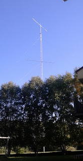
This will serve as an interim solution for rotating the upper yagis of my 15 and 20 meter stacks this winter. As you can see in the picture the upper 15 meter yagi is installed. The upper 20 meter yagi remains on the ground, delayed by a variety of non-radio chores that must be completed before the weather gets colder. 

Slow or not, direction known or not, it is going to be used this winter season. Its limitations are things you learn to accommodate in your operating when you insist on home brewing these crazy projects.

Tuesday, September 22, 2020

Virtual Gatherings

Soon after lock downs became common across the globe this spring there began a rise of virtual gatherings. Amateur radio clubs and other organizations joined the trend. Although we are communicators by nature it is difficult to hold a meeting on air among a geographically dispersed group with a wide range of equipment and antenna systems. If you've ever participated in an HF net you'll understand.

I welcome the shift to virtual. It will continue to have important advantages even after the virus is defeated. We should learn to do it and to do it well. RAC (Radio Amateurs of Canada) held their AGM (Annual General Meeting) and associated conference this weekend using Zoom and it was an eye opener. It had its ups and downs, and despite a variety of problems showed how good it can be for our hobby.
  • It was interesting to see the insides of many shacks across the country and around the world. How else would I know that the President of ARRL, K5UR, had a love of old tube equipment, of which there was plenty in his large shack.
  • Avoidance of travel enabled far greater participation, including internationally. It isn't often you can watch a live discussion among the leadership of RAC, ARRL, RSGB and IARU. From the call signs displayed the conference included attendees from at least several countries.
  • There has been great success by many clubs to replace or supplement in-person meetings and have interesting presentations by club members and to club members from other hams in distant places.
  • RAC and other organizations and clubs have had tremendous success holding license classes that are likely to result in a significant increase in new hams in the coming months. They are popular and convenient, but until we have numbers in hand we won't know for sure.
One thing I learned is that large and complex meetings are not easy to organize and run. A friend experienced with Zoom in a professional environment warned me about that. Services such as Zoom are quite easy for attendees to use with almost no preparation when it is for just a few participants. Whether via the internet or in-person, large events are never simple. There were many challenges and problems during the RAC event despite the many experienced people working behind the scenes.

We will get better at it, and we must. I like the convenience of doing these meetings from the comfort of my own home or in the presence of a few within my social circle. It is quite a change from the business video conferences I regularly participating in during my career, going back to the 1980s! There is no need for special equipment, dedicated video conference meeting rooms and a technically specialized support team.

My terrestrial wireless internet service is quite poor and not up to the challenge of video, in particular in the upstream direction. As a consequence I have no PC cameras. It is possible to use Zoom and similar services with video transmission disabled although that removes some of the inter-personal benefit, but I have done it and it works fine. It is good that Zoom adjust video size and quality to fit within the available bandwidth when the pipe is narrow.
 
For my own presentation in the RAC conference I had to join in from a friend's QTH to have full two-way video. We had to scramble before the start when one laptop developed an intermittent hardware failure and he had to configure the software on a second laptop. We got it done barely in time. There were intermittent connection problems throughout that we could not solve and had to live with.
 
Despite our effort the webinar forum failed entirely halfway through my presentation and was apparently not recoverable. Unfortunately no one knew and assumed the problem was on their end. The Zoom service is not very communicative to participants of what has gone wrong. In this case it appears to have been on RAC's end and not the Zoom service. 
 
Numerous attendees contacting me during and after the aborted presentation wondering what had happened. I didn't know and I still don't know. Good communication from the conference organizer is needed to complement the technology because the technology won't deal with these organizational matters. That is something to keep in mind or the experience will be a bad one for many.
 
The time is rapidly approaching to upgrade my internet service and buy a camera. My only camera-equipped laptop is an antique of Windows Vista vintage. As virtual meetings become more common there is an unavoidable need for speed. 
 
I am beginning the planning of a video conference for an amateur radio group to take place this winter and I can now see what I've gotten myself into! There is a lot of organizing and coordination required, and the people to operate a large conference behind the scenes. I may regret this.

Note: I always feel a little bad when the pace of technical articles slow and I "fill" the space with articles such as this one. The reason for the delay is that I am busy doing those technical things that eventually make their way into articles. The season is racing onward towards winter and I am very busy. The technical articles will reappear, I promise.

Sunday, September 13, 2020

Transition Season

This is the time of year when I prepare for the transition from summer to winter. Some of the tasks are unavoidably annual tasks and others are due to the incompleteness of my antenna farm. The former includes the following:
  • Clearing brush from antennas and cables
  • Inspecting low band receive antennas for damage and make repairs
  • Inspect towers, including cables, bolts, guys and antenna connections
  • Inspect exterior electronics and clean or repair if needed
Our winters are not a good time for precision work outdoors. It can be done but it can be very unpleasant. Usually I try to limit myself to critical repairs and work that requires nothing more delicate than a large wrench. Even then I schedule work during the rare warm days. 

In the second category are these items:
  • Disconnect the 6 meter antenna and connect the 160 meter antenna
  • Put up the full size 160 meter vertical antenna
It doesn't look like much but it adds up. Were I not retired it would be difficult to get it done. Most items in the second category will vanish when the station is more complete. So I've been busy.

Beverages

The ticks are gone but the vegetation is in full growth. However I did have to evict a colony of earwigs from a junction box at the base of one of the towers, and wasps are beginning their annual infestation of the towers that they are attracted to for some reason. They are not a danger in this state.
 
The northeast-southwest Beverage developed an intermittent problem and then complete failure in late spring that primarily affected the reverse (southwest) direction. I don't use it much in the summer so there was no reason to risk the ticks or tripping over invisible obstacles. I suspected a loose ground wire at the northeast termination.

On a wet day when not much else could be done I donned suitable clothing, filled a bucket with tools and parts and entered the "jungle". I took the picture below to give you an idea of what it looks like. There is a two-wire Beverage in there that is very difficult to pick out amidst the vegetation!
 
Much to my surprise the intermittent and total failures had independent causes. The intermittent was due to rapid bush growth into the two wire Beverage that pushed the wires together in two places. This is despite the aggressive cutting I did in late winter when I twinned the Beverage to make it reversible. When the wires touch the differential mode required for the returning southwest signal is disrupted.
 
 
I cut the worst of it and the rest can wait until winter when the growth dies and the ground is more walkable. The total failure was due to the lower wire being severed a few meters from the northeast terminal. A brief forensic analysis suggested an encounter with deer antlers rather than malice and no trees had fallen. I have never seen signs of other humans that deep in the bush and the broken ends were not cut with a tool. The wires slope down toward the termination and that makes them vulnerable to deer. That it was only the lower wire reinforces the conclusion.

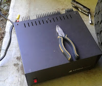
Luckily aluminum fence wire isn't difficult to splice by hand since the one tool I needed -- pliers -- wasn't in my bucket. I tensioned the wires after the repair and made sure it lifted off the bushes and trees during the walk back. There's a lot to cover over the 175 length of the Beverage. I'll improve the splice and make a few improvements after the ground freezes. Perhaps a bit of yellow hazard tape hanging from the wire will persuade deer to duck their heads! The antenna now works as it should.

Protecting aerial cables

Due to trees and other obstacles all the cables from the big towers and other distant antennas is not buried near the house. I have an aerial messenger cable to carry multiple runs of Heliax and control wire from the surrounding stone wall to the Trylon tower near the house. All switching and wire connections are done at the base of the tower.

There are many trees surrounding the yard and unfortunately most are birch. I say unfortunate because they grow like weeds and only live for 40 years. These trees are 25 years old. Branches grow quickly in the space over the aerial runs and threaten them by breaking off in high winds and ice storms. Regular trimming is mandatory to avoid catastrophe.

This was my first major trimming the aerial run was built in 2018 and there was a lot to clear. There is one major limb left to be cut but that will require more care since cutting it risks damage to the cables below. For now I am relieved to see daylight around the aerial cables.
 
I am very tempted to chop down the two adjacent trees and remove other obstacles so that I can safely bury the cables. That's for the future and until then I will continue the annual trimming ritual.

160 meter antenna

Unlike previous years I am using a buried Heliax run to the new 140' tower for the seasonal 160 meter antenna. It is connected and ready to go. The antenna cannot yet be deployed because the 20 and 15 meter stacks are incomplete. The tram rigging for the final antenna -- the upper 5-element 20 meter yagi -- cannot coexist with the wire antenna supports. 
 
There is also the matter of radials which lie on the ground. Those are a serious safety hazard for my crew. I like to protect my friends from injury! Deploying of the radial will have to wait.

Another matter is the location of the antenna which will be different from previous years. There is modelling work to be done to ensure there are no coverage gaps. The towers act like reflectors and although poorly tuned as parasitic elements they skew the pattern several decibels and increase ground loss (via the lightning ground rods). After the modelling and other antenna work on the towers are done I will proceed with the installation.

My summer 160 meter antenna is marginally acceptable. I find it frustrating calling DX stations that hear me weakly or not at all that would be easy with the full size vertical. The smaller antenna serves its purpose well enough but it is not suitable for serious DX and contest use. I estimate that 1 kW to it works as well as the full size vertical with 200 watts. That's an estimated deficit of 6 to 7 db, a little worse than the model predicts. Ouch!

Yagi on deck

Rigging of the heavy 5-element 20 meter yagi is being installed. The tram for a 110 lb (50 kg) antenna (add 30% for the rigging) has to be stronger than for antennas half that weight. The yagi is tuned and almost ready to go. It is shown below in position for attachment to the tram. The lift should take place before the end of September.

 
The delay has several causes which I won't go into in this article. The most important is completion of the mast system. The missing piece is the prop pitch rotator which is needed to control the mast direction and to hold it in position for the lift operation. The motor is installed and operational but not yet coupled to the mast. The weather hood and the direction indicator remain to be built.

With the completion of the 15 and 20 meter stacks the summer construction season will officially be at an end. Despite delays the project should be complete in October.

Howling at the...train?

We have a lot of coyotes. They roam in packs or solo and are occasionally seen in the fields or the verges of the bush. My farmer neighbours take a dim view of their presence and will shoot them if they threaten their livestock. They have mostly learned to avoid humans and their dwellings. 
 
In winter their tracks are found everywhere in the dense bush snow cover. When I revisit my Beverage sites on consecutive days I find their tracks alongside mine. Most nights their howls are heard from afar and sometimes close by. They are not often heard in the daylight.

One recent exception is a pack in the large bog that covers the east corner of my property and several adjacent properties. It's dry this time of year and easily traversed by wildlife. The coyotes hunt throughout the area killing deer, turkeys and anything else they can catch. In a way I can claim that they are protecting my Beverages from deer damage (see above).

The passenger train service between Ottawa and Toronto passes 1.5 km to the east and following the pandemic lock down service is back to normal with frequent passages of the trains. When the trains toot their horns at road crossings the coyote pack have taken to howling in accompaniment. 
 
While on the tower this week the howling was quite loud and was also heard by my friend on the ground. I can pretty well locate where the pack is located although I cannot possibly see them in the dense bush despite being 40 meters high, far above the tallest trees.

Despite the coyotes not being welcome their howling along with the trains is entertaining. I've gotten to the point of stopping and listening when I hear the trains and like clockwork the howling begins. Living in the middle of nowhere has its advantages.

Upcoming articles will include ones about the prop pitch rotator, the 15 and 20 meter stacks and the new full-size 160 meter vertical. Amidst this and other responsibilities I am having trouble finding time to write articles for the blog. Hopefully this one is interesting enough to fill the void.

Thursday, September 3, 2020

40 Meter Dipole (aka Yagi Element) Installed

The experimental 40 meter yagi element is now complete and it is installed high in the sky. Before being raised a few changes and additions were required:
  • Continuous centre pipe, replacing the split centre dipole feed
  • Fitting the 2.375" schedule 80 centre pipe to the 1.9" OD pipe with a shim and a recessed bolt for a good mechanical and electrical bond
  • Fitting the custom capacitance hat clamps and replacing the nuts with nylocs
  • Gamma match built, fitted and tuned at a lower height
  • Mast clamp made from an ancient aluminum plate and even worse muffler clamps
  • The antenna was resonated at a higher frequency so that it would exhibit capacitive reactance, which eases gamma match adjustment
There are two reasons for installing the antenna. First, to test its robustness over a cycle of seasons, including wind and ice. If deficiencies are discovered I will correct them before constructing a 3-element yagi. The second is to have a high 40 meter antenna this contest season. Although it is not directional I want it for working distant DX multipliers and also on shorter paths as the MUF drops in the evening. 
 
Cycle 25 has arrived but for at least the next year 40 meters will continue to go long early in the evening. The XM240 at 21 meters height work well but sometimes it is too low for the best results. The broad pattern will come in handy for working stations when the XM240 is pointed elsewhere.
 
Gamma match
 
The antenna was trammed to 70' (21 m) to adjust the gamma match. It is far easier to do it there than at 150'. The rigging was already in place for another job so it was convenient. A dipole's impedance changes with height so I made allowances in the gamma match design. A final adjustment would be done when it was at its final height. The adjacent TH6 had only a small effect on the tuning.
 
I used gamma match software to determine the approximate gamma rod length and capacitor value. They were built longer and larger, respectively. Although all the software I've tried does poorly since gamma matched are fickle creatures it at least gave me something to shoot for. 
 
The rod is telescoping sections of ¾" and ⅝" tube, chosen for the ratio of ~4 between it and the parallel element sections. The straps holding the gamma rod (one conductor and one insulator) were made junk box parts. Gamma rod spacing is 12" centre-to-centre.
 
I started the adjustment with a variable capacitor to speed the process. I measured the capacitance for the matched position and made the final capacitor out of RG213 (shield removed) and inserted it into the gamma rod. Unfortunately that didn't quite work out. Inside the large tube the capacitance was only 1.5 pf/inch (0.6 pf/cm) versus 2.1 pf/inch when inside a ½" tube. A 180 pf capacitance (the estimated value +20%) far too long. 

I made another capacitor with an intact length of RG213, using the shield as the inner plate. That was much better at 4.8 pf/in (2 pf/cm). The PVC coax jacket is higher loss than the polyethylene inner dielectric but it is quite low at 7 MHZ. I added a layer of vinyl electrical tape for a higher flash over voltage, just in case.

A challenge with the adjustment is that the gamma match for 7 MHz is large. The strap is outboard at 7' to 9' (2.1 to 2.8 m) and the gear clamp for the telescoping rod is at the end of a 4' (1 m) tube. The latter can be reached with care but the former requires 90° rotation of the antenna and a way to hold it in position alongside the tower, and to do so with damaging the antenna and other tower attachments.

Adjustment of the match will be easier on the yagi. The element can be rotated on the boom to bring its full length within reach of the tower. All it takes is pointing the antenna where the rotation can be done without striking guys and other obstacles.

Rigging

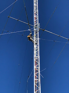
A conventional tram line was used for lifting the antenna, with one important difference. The 40 meter antenna was to go to the top of the mast and the TH7 was in the way. The TH7 was turned so that the elements were parallel to the tram. The 40 meter antenna is given the same orientation, which is a little unusual (see pictures below). The challenge was to thread the antenna through the space between the TH7 elements and around other obstacles.

The tip to tip span of the capacitance hats is almost twice that of the opening between the TH7 driven elements. Further, there was no good way to attach a tag line for steering the antenna that would make it easy to remove it afterward. It would be too far out on the antenna to be reached and looping it around and down could easily damage antennas and tangle in the guys.
 
 
The solution was quite simple. As the upper tip approached the tower I ascended and manually steered it. I followed it up, directing it around the top guys, outboard prop pitch motor platform, TH7 elements, over the boom truss and past the mast. The last is critical since it's easy to forget and direct it to the opposite side of where the mast clamp must be. The antenna was rigged to be well balanced and it could be steered by the ⅜" tip with a light touch.

The difficult part was inserting the arms of the mast muffler clamps through the clamp plate. The antenna must be held level and flat on the plate long enough to get at least the first washer and nut on. Since the antenna was rigged to point upward to ease the threading operation the antenna was not level. Standing on top of the tower holding a 62' long and 55 lb antenna level against the weight imbalance and breeze while threading the clamp is, to put it mildly, not easy!
 
I recruited the tram line rope (now slack) to grip the "lower" side of the antenna to hoist it level and knotted it to keep it there. Although it rocked in the breeze it was stable enough to get the job done. The antenna was now halfway up the 10' mast, just above the TH7 boom truss. After descending for a lunch break I returned to adjust the gamma match (see below) and complete the lift. 
 
I stepped the mast and moved the pulley to the top. My friends pulled from below as I slid it upward. It went slowly because the clamps like to grab the mast. It's difficult to perfectly balance and align the mast clamps. I adjusted the gamma match, trying different antenna orientations, and then bolted it down and removed the rigging. 
 
A short length of RG213 connected the antenna to the rotation loop (already present). The coax was tied to the mast and the joints sealed. Mission accomplished. This description of the process may be too much detail for many readers but for those contemplating similar lifts the details may be helpful.

Adjusting the match

The impedance of a 40 meter dipole is affected very little by higher band antennas and the segmented guys. This is the expected behaviour for interactions with shorter conductors. 
 
The ground is a greater concern since for a 40 meter dipole since, relative to wavelength, it is never far away. Yagi impedance becomes independent of ground at low heights because they are directional.

Using EZNEC I calculated the impedance shift from the lowest tuning height of 21 meters (λ/2) to 46 meters (1λ). Unfortunately the transformation of that shift via the gamma match is difficult to predict. I've had poor experience accurately modelling gamma matches with software tools. Also, a gamma match is not ideal for the high R of a dipole but I wanted to test this as well as part of the 40 meter yagi project.

I did get an SWR of 1.2 at 21 meters height although I had bottomed out the gamma capacitor. I should have made it longer. Since it was close enough I decided to go with it for the final lift. The SWR was worse up there since R ended up higher, moving the gamma rod strap was too difficult and there was residual reactance the capacitor wasn't large enough to correct. 
 
The SWR was no better than 1.5 and rose to 2 at 7.3 MHz. It could have been improved but it was late in the day and I was sore from all that hanging from the top of the mast. I can replace the capacitor later if I'm so inclined. I may not bother.
 
The match is different when the 40 meter dipole is parallel to the TH7 elements or boom. It is mostly unaffected by the elements, which are short compared to the antenna, but there is coupling to the boom and truss when parallel to the boom. This occurs because the TH7 in this orientation looks like a 40 meter dipole (the boom) with large capacitance hats (the outer elements). 
 
With a suitable matching network the TH7 could be used as a poor 40 meter dipole. Likewise a 3-element full size 40 meter yagi can be used on 80 meters with a suitable matching network. An omega match is a good choice. However it requires other changes that are beyond the scope of this article. 
 
I oriented the dipole parallel to the TH7 elements which is the sensible choice with regard to interactions and operating convenience.
 
Performance
 
Testing of the antenna's performance is just beginning. It's about more than traditional antenna metrics. "After all," I said, in reply to a friend who asked me how well it works, "a dipole is a dipole." This is what I want to learn:
  • Wind survival
  • Ice load survival
  • Gamma match survival
  • 15 meter interaction
  • Height advantage or deficit
The wind surface area (cylindrical projection) is 9 ft², including the boom-to-mast clamp and gamma match. The gamma match alone is 0.65 ft². The capacitance hats are robust but they stress the element where they are attached. I put them at the outer edge of the 1" × 0.120" tube rather than farther out -- where they would have more effect -- on a tube with 0.058" wall thickness. The total wind surface area of both capacitance hats is 0.5 ft².
 
The SWR of ~1.5 I measured on the tower was replicated in the shack. Then it rained and the SWR improved. After drying out it got a little worse but was a perfect 1:1 a little below the band edge. Clearly something odd is happening. Next time I'm up there I'll do an inspection. It may be nothing more than rainwater in the gamma rod. An unexpectedly low SWR is no less worrisome than a high SWR.

Notice that the SWR is high on 15 meters and that the third harmonic is ~24 MHz. This agrees with the measurement during experimentation and meets the design objective. As noted earlier the 15 meter SWR of the TH7 below it barely budged. I have not as yet tested the 15 meter pattern and some deterioration would not be a surprise. That is acceptable since the 15 meter stack will soon be online; for the next year the TH7 will contribute more as a high 10 meter yagi.

The antenna is noisy on 40 meters because a dipole is not very directional. A yagi pointed north of an east-west line is typically quieter from here because northern latitudes experience less violent weather. Despite that the comparison to the XM240 has proved interesting. Keep in mind the XM240 has ~6 dbi gain which is 4 db more than the dipole. On many receivers that is 1 S-unit.

My on air testing was delayed by a geomagnetic storm that erased most signals and altered elevation angle behaviour of DX signals. When conditions improved I tried again. Really, there is nothing exciting to report. It's a dipole high in the sky, and that's how it behaves. Mostly it served as a reminder of how height affects antennas, and that different heights make a difference, though perhaps not always as you might expect.

The lower XM240 was always better before sunset and during the geomagnetic storm since signals at low angles are more attenuated due to the longer path through the absorptive D and E layers of the ionosphere. Under more favourable conditions the high dipole is roughly equal to the XM240 on intermediate paths. On long paths the high dipole is better. It is also better to Europe later in the evening when the MUF drops closer to 7 MHz and favours low elevation angles.

Comparing antennas with equal gain would more often favour the higher one based on these early observations. The poor directionality of the dipole came in handy to hear and work stations in diverse directions, but often required help of a Beverage on receive to improve SNR. While not ideal for general operating it can be an advantage during contests.

I was rudely reminded of the ferocity of precipitation static on high antennas. When it occurs you use another, lower antenna or you listen  with low band receive antennas. Lower antennas suffer less from the effect.

With the 40 meter antenna in the air I am free to finish the work on the 20 and 15 meter stacks. Winter is coming and there is much yet to be done.

Photo credit: The two pictures showing me on the tower were taken by Alan VE3KAE.