I haven't said much about revamping my automated control system since mentioning it a few months ago. A lot has happened since then. That said, progress has not been rapid because it was summer, and summer is a time for other activities. Despite the many delays the software is not far from completion.
Well, that's the software. Where I have been more reserved is with my decisions for the hardware. Software cannot on its own do anything: it must be connected to the real world. On an Arduino and similar systems the GPIO (general purpose input output) pins are the interface between the two.
I have waffled between solid state and relay switches to put signals on the control lines, weighing their various pros and cons. Now that I've made firm decisions and begun implementation I thought that this would be a good time to discuss my investigation and experiments, and the reasons for my choices. This could prove of interest to others, hence this blog post.
Despite being oriented towards contesting, the presented information should be of broader interest. Our increasingly software-centric shacks enable opportunities for station automation and remote operation that we could only dream about in the past.
I do not claim expertise. What I can do is explain the how and why of my design choices. There are many online resources that delve into greater detail, and there are commercial control solutions for the ham shack. My citing of these will be sparse since that is not the topic of this article.

Using GPIO on Arduino
pinMode(gpio#, OUTPUT);
It may seem obvious but don't forget to include the above code in your Arduino sketch. I've forgotten a few times and the result was confusing behaviour. You can perform a digitalWrite on GPIO pins that have not been so declare (the default is INPUT) except that the GPIO may only supply a few milliamps before a logic HIGH sags to become a logic LOW. I now make sure to declare all the GPIO pins as OUTPUT during initialization (reset).
GPIO output pins default to LOW. That seems sensible since we tend to think of LOW as off and HIGH as on. That is often not the case. There are good reasons to use reverse logic (LOW is on) to simplify connection to external modules.
I posted a picture of a midsize Arduino. Mine is a Mega. I need the Mega's large number of GPIO pins due to the sheer size of my antenna farm and shack equipment. Most hams can get by with less.
What I need to switch
The mosaic of switches that can be found in my station are collected below. It is partial since there is far more.

Going clockwise from the upper left, and then the centre:
- Beverage remote switch
- Head end of a reversing Beverage
- Stack switch
- 2×8 antenna switch (Hamplus)
- 80 meter 3-element vertical yagi
- Parasitic element (there are 4) of the aforementioned yagi
- Relay board of the 6-band low-power BPF (VA6AM)
As you can see there are many relays in the RF path. To reach those remote switches there are multiple DC control lines that wend their way out to and up the towers, below ground and on the ground. There is a lot for the station automation system to connect and manage. Further, the threat of lightning is ever present and therefore the risk to control system electronics in addition to its more spectacular effects.
I am not able to switch the amplifiers at present because they are manually tuned tube amps. My plan for the future is for modern amps that can be automatically switched. An alternative is RF-detection that is available in an increasing number of amplifiers. A few milliseconds of transmitted RF will switch the band and ATU setting automatically.
Switching devices
GPIO pins can't deliver enough current to directly switch the switch the relays shown above, and if you try there is risk of damage to the Arduino. Many control lines power multiple relays so the current requirement is even higher. It is also unwise due to the risk of damage to the processor from pulses and surges from relay coils, precipitation static and induction from nearby lightning strikes. On the bright side, all of these components, including Arduino boards, are inexpensive.

At right are several choices for switching devices. Clockwise from left, and then the centre, are:
- 2N2222A NPN transistors
- The same devices mounted on a proto-board with base resistors and current-limiting load resistors (e.g. for LED or a second switch stage); an SPST reed relay is shown, though not connected
- ULN2003 NPN Darlington transistor arrays
- Module with high current relays and drivers suitable for direct GPIO connection
- 2N6034G PNP Darlington transistors
The solid state devices are cheap and easy to buy in bulk from online suppliers. They are small and quiet, which is nice for use within the shack.
Darlington transistors are important for switch voltages higher than that of the microprocessor logic. With a single transistor (Darlington transistors have two in series), there is a substantial risk of the higher switched voltage destroying the microprocessor.

During prototyping I tried all of the possibilities. In the above photo the NPN drivers are lighting LEDs that represent one side of the 2×8 antenna switch; the port for the 20 meter stack is selected. PNP Darlington transistors on the lower right and their NPN drivers light LEDs for the 10 meter stack switch. The upper yagi is shown as selected. The relay module is connected but with normal logic (see next section) none of its relays will switch on.
The power supply PCB (upper right) with two 5 volt regulators is not being used. USB 5 volt power is the sole power source. The relay module has 5 volt coils, however the only reed relays on hand have 12 volt coils that could not be tested without a 12 volt supply connected.
Reed relays are quiet and small, and well suited to the modest demands of control line switching. The relay modules are larger and louder but they're cheap and easy to connect to the Arduino. If size and noise are a problem it is possible to locate them outside the shack with a wireless Arduino shield. That is my ultimate intent.

A benefit of using SPDT relays is that when the control line is idle it can be grounded by connecting the NC terminal to ground. That is only possible with high-side switching; with low-side switching, grounding the NC terminal energizes the circuit, which is not what we want. This brings us to the next section.
High-side and low-side switching, and switching logic
The switch (mechanical or electronic) can be placed on the low side or high side of the circuit. The diagram at right shows both. The supply voltage is applied at the high side of the load (e.g. relay coil) and a low side switch grounds the load to complete the circuit. The opposite applies for a high side switch.
You don't always get to choose. All of my home brew antenna switches are high side. The Hamplus 2×8 antenna switch requires low side switching. The same is true of almost all amplifiers, where you ground the control line to bring the amp inline when transmitting. I prefer high side switches for outdoor equipment so that the power supply is not continuously in circuit, leaving the power supply exposed to all potential occurrences of static and surge. In practice it's no big deal and I may be overreacting.

Whichever you want or require there are implications for how the GPIO are used. With a solid state switch you can use either NPN or PNP transistors. The choice is not arbitrary since they are not equivalent.
- NPN: normal logic (HIGH is on) and low power dissipation.
- PNP: reverse logic (LOW is on) and high power dissipation.
Vce is very low with an NPN switch so that the I²R loss is also very low. Vce is typically 0.6 to 0.8 volts with a PNP switch and the loss is higher. That is why it is common to see NPN Darlington array chips and individual PNP Darlington transistors with a heat sink option (see the picture above). With the small relays we typically use the power dissipation is modest and a heat sink is not required.

With normal logic and high voltage (12 volts is high when dealing with a microprocessor!) a high side switch requires a complementary Darlington transistor: NPN followed by a PNP. Since there are pretty well none of these devices commercially available it must be constructed from individual transistors, and the parts count is high. That adds up when you have dozens of control lines to switch. With a PNP Darlington you escape that if you use reverse logic (LOW is on).
For the typical multi-relay modules marketed to Arduino users you can directly connect them to the GPIO pins if, again, you use reverse logic. With normal logic an NPN driver is required to invert the logic.
My choices
After looking at the effort and cost required for the various options I have settled on my final choices for switching devices.
- Indoor equipment: Darlington transistors
- Outdoor equipment: Relay modules

Relay modules are surprisingly inexpensive from multiple online sources. This stack of 48 relays cost me only a little more than $1 (CDN) per relay. That many relays might seem excessive at first glance until you consider that just the 2×8 switch requires 16 relays. The small PCB at the lower left is for one of the 6-band BPF. It is partially populated with PNP Darlington transistors.
By restricting myself to these two options I will use reverse logic in the Arduino. I recommend that you use similar code as that below when doing this. You can easily switch between normal and reverse logic by changing just two global variables. Mixing logic in an Arduino sketch can cause confusion during coding so I recommend sticking to one or the other.
int R_OFF = HIGH;
int R_ON = LOW;
digitalWrite(gpio#, R_OFF);
digitalWrite(gpio#, R_ON);
There are no NPN drivers required at all! The PNP Darlington transistors are driven directly by the GPIO pins with only a base resistor: 3.3 kΩ appears to work well for the 2N6034G. I have designed control boards for the BPF to support both manual and automatic band selection. Other than the transistors all it contains are bypass capacitors, base resistors and several Dupont connectors.
The relay modules connect directly to the GPIO pins. Except for the 2×8 switch (low side switched) the NC relay terminals will be grounded for lightning mitigation. The system will be large with all the relay modules stacked. It will be placed out of sight under the operating desk.
When I transition to Wi-Fi to untether the control system from the PC, it will be placed where the relay chatter can't be heard at the operating desk. Lightning protection for the station can be better when the control lines are kept out of the shack and closer to an external ground. A small 13.8 VDC power suppy can be colocated with the remote control system.
Next
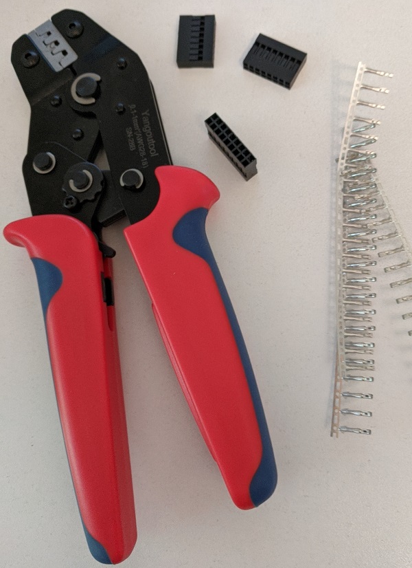
Cabling is no small job. There are over 100 Dupont connectors to be assembled, most in groups, for connection to the Arduino, relay modules and BPF PCBs. A crimp tool is essential for the work to proceed smoothly and to produce reliable connections.
There are multiple DB9 and DB25 connectors and cables to/from peripheral equipment and the control cable patch panel in the basement. It's a tedious but necessary job.
For the initial installation I might not use an enclosure for the control system. The quantity of connectors and an almost guaranteed need for future changes makes for difficult and perhaps unnecessary work. Provided there is sufficient RFI protection it can be left "open" until the design of the control system matures.
With a little luck and some hard work the full system should be ready for CQ WW SSB at the end of October. Well, that's the ideal, but with all the tower and antenna work I am doing for myself and others I might not be done in time. I'll have more to say about the full system once it is complete and it has been used in at least one contest.
Love this blog, such a great resource and has helped me so much in many ways. Thank you :)
ReplyDeleteFor high side 12v relay drivers (grounded remote antenna switch pcb) I use PS2502 (optically isolated darlingtons) driven by Arduino for a simple interface. Also use PC814 isolators on the input side for reading band bitmap state, TX state on the radio.
Not sure if you have seen this, https://github.com/k3ng/k3ng_rotator_controller for very adaptable Arduino rotator control firmware -- Fantastic project!
tnx agn es 73 ;)
Jessy VE4JBB
Thanks for the kind words Jessie. Yes, there are many devices and what I used is in no way meant as a recommendation. It's simply what I had. However, as I pointed out, I am using relays for all outdoors control lines due to the risk from lightning etc. An opto-isolator is no protection from that. Regarding the rotator controller, yes, I know of it, and there are others out there. It'll be a while yet before I act on this item.
ReplyDelete73 Ron VE3VN
There is also the possibility of using optocouplers to isolate the cpu i/o.
ReplyDelete