This winter I called a rare DXpedition on 160 meters FT8. I don't normally do this and I had already worked them on CW. It was purely opportunistic since I was there, I heard them and I had the time. I flipped on the amplifier (they were very weak) and went at it.
After several minutes of calling I received a signal report from them. I replied with the usual FT8 R-nn message. I resent it many times since I did not copy RR73 from them. Indeed perhaps no more than 10% to 20% of their messages were strong enough to be decoded. I did not yet have a Beverage antenna for their direction so I was manually switching between my 160 meter antenna (transmit) and 40 meter yagi (receive) which had a better SNR than the vertical.
I never did decode an RR73 message for our QSO. The few messages successfully decoded were directed at other stations. Eventually I gave up. There are several scenarios in which an FT8 QSO is deemed to be complete but this isn't one of them. At a minimum each station should copy a reception confirmed message and I didn't have one from them.
When I later searched their online log there I was in their log with an FT8 QSO on 160 meters. Apparently they did receive my R-nn message and responded with an RR73 that I failed to copy. For all I know they sent RR73 more than once in reply to my repeated R-nn messages. I'll never know.
My personal ethics on the matter are clear: this was not a valid QSO and I did not claim it. Not everyone agrees. I know people who believe that all I need to do is create and upload the QSO record with an estimated time. LoTW (Logbook of the World) and other QSO matching services have what I consider an overly generous latitude for timestamps. I knew this and deliberately did not note the time since the QSO was not valid.
Despite my passion for DXing the claiming of a rare country in this circumstance repels me. As I noted, there are others who would disagree. For many the DXCC "counter" is justification enough for bending the criteria for what is considered a valid QSO, especially when the DXpedition logged the QSO.
Indeed this is an inherent flaw of the RR73 message since it signals that the QSO is being logged by the sender with the expectation that the message is received and successfully decoded. That is never certain. In this respect FT8 and similar digital modes rely on the good faith of the operators.
Similar circumstances can occur on SSB, CW and RTTY but have historically been less controversial. FT8 brings the matter into stark relief because there is no muddy middle: RR73 is copied or it is not. There is no room for operator judgment.
That sums up my attitude toward digital DXing. I am not personally satisfied with a QSO that does not fulfill the minimum requirements. I take no pleasure in claiming a QSO that I deem invalid.
Monday, April 27, 2020
Friday, April 17, 2020
Reversing the Single Wire Beverage
In my previous article on the reversible coax Beverage receiver antenna I said that my next Beverage would be the same oriented east-west, and that it would be done shortly. I lied.
Due to circumstances I've put that project aside. Purchasing a 150 meter reel of RG6 became more difficult and expensive due to the pandemic lock down with delivery uncertain. Then there were unresolved difficulties along the planned route of the east-west Beverage. Some of the trees are quite large and old with rot and other challenges that would require additional effort to prepare the route.
What I did have was half the 400 meter (¼ mile) reel of aluminum electric fence wire left over from building the 175 meter long single wire northeast Beverage. All I had to do was hang it along the same route to make an open wire transmission line Beverage so that it could be electrically reversed. The switch to select direction is slightly different than that for coax due to the use of a balanced transmission line. The critical difference is the transformers, two of which are more complex to build and test.
As you read this article you may wish to refer to the linked articles for details I am not repeating in this one, especially that for the reversible coax Beverage. This includes references to other material, links to which are largely not provided here.
How it works
As before let's start with the rough schematic of the two-wire Beverage from ON4UN's Low-Band DX'ing book. My article on the reversible coax Beverage reviews the basic operation of the reversible Beverage. Here I will largely limit the discussion to the differences between a coax and open-wire line Beverage, covering both the physical construction and the electronics.

As before signals from the right don't see T3 and signals from the left don't see T1 and T2. Due to the travelling wave behaviour of the Beverage the signal is zero at the antenna's forward edge. The signal builds as it travels along the two parallel wires to in common mode: signal amplitude and phase are identical on the two wires.
Signals from right build up along the length of the open wire line and encounter T2. This signal does not appear at the secondary winding because there is no potential difference on the two ends of the primary winding. Instead they combine at the primary centre tap and are fed through the primary of T1 to ground, making that transformer functional. The impedance is stepped down to that of the coaxial feed line. T1 is identical to that in the coax reversible Beverage since the surge impedance is approximately the same.
Signals from the left are also common mode when they encounter T3. The same behaviour occurs, But this time the common mode signal from the secondary winding centre tap flows through the primary winding to ground. Signal energy is coupled back into the open wire line in differential mode so that the two wires now behave as an open-wire transmission line. This signal power couples through T2 and is transformed to the impedance of the coax feed line.
Operation is a little tricky but is understandable when you study the schematic for a few minutes and carefully trace the signal paths. The reversible coax Beverage is easier to understand since the exterior of the coax is the Beverage antenna while the interior of the coax is the transmission line. For the two wire Beverage the two wires do both tasks.
Physical design
Twinning the single wire Beverage easier than putting in a new Beverage. It took about a day's work spread over 3 days to fabricate parts, clear brush and install the wire. A few of the tree insulators had to be moved to accommodate the second wire and the higher tension. Unrolling 175 meters of aluminum wire and routing it through the bush was probably the easier task!
To simplify construction I oriented the wires vertically. Since this can introduce imbalance (relative to ground) the wire spacing is just 10 cm (4 inches). Doing it this way saved me a lot of work since the original Beverage is sometimes supported on the left side of a tree and other times on the right. Rerouting the first wire is very difficult and dealing with rotation for wire crossover has its own challenges.
I can add rotation in its vertical orientation should I suspect an imbalance. This seemed unlikely based on the reported experience of other hams. Initial performance tests (see below) appear to confirm this.

Several methods are used to support and space the wires. There is a mix of commercial electric fence wire supports and ones I made from PVC pipe. The higher tension allowed me to eliminate a few of the tree supports. They were no longer needed or they were sufficiently out of line to develop excess lateral force.
Simple PVC spacers were used on the longer unsupported spans to keep the wire spacing uniform. Small gauge copper wires tie keep the wire from slipping out of the slots. I first used this technique several years ago to build a multi-band inverted vee.
Nails are galvanized 3" straight framing nails. Since the trees grow around them to repair the damage leave some of the nail shafts exposed. The force on the nails is quite low so they won't bend or split the living wood. As trees grow and die the supports may have to be moved or replaced. Although the trees can handle the injury this is wild bush where the trees are expendable.

The terminations are more difficult than with a single wire or for the coax Beverage. Ideally we want a smooth curve down to the electronics. Unfortunately mine take a sharper angle. On the left is the feed point (southwest end) and on the right is the northeast end deep in the bush alongside the swamp.
Some improvement is required though, as we'll see, performance seems unaffected. If nothing else the boxes need to be firmly anchored to prevent connection fatigue and crossing each other. Occasional tree contact doesn't seem to affect performance. Now that testing is complete I'll proceed with the "finishing" work. The ground wires are a little long because the ground rod had to be away from tree roots and the open wire line is difficult to route downward. This doesn't noticably affect performance.
Electrical design and transformers
The ON4UN circuit for this type of Beverage is reproduced here along with annotations for the impedances and transformer turns ratios for my chosen design. There is flexibility in the selection of impedances to permit finding a good balance between physical design (wire size and spacing and Beverage height) and transformer design (turns count and ratio and centre taps).
The size, spacing and height of the two wires determine the surge impedance. There are two of them: common mode for the Beverage antenna (both directions) and differential mode for use as a transmission in the reverse direction. Although the precise impedance values are not important in themselves the choices are critical for designing the transformers.
What we ideally want for both is an impedance that allow for an integral number of turns on the primary and secondary windings on the 3 transformers for an exact transformation ratio. This is next to impossible and is not an absolute requirement and the common mode surge impedance will vary from a theoretical calculation. We want to get close so that performance is what it should be.
The surge impedance of the open-wire transmission line is easily calculated and with a small spacing relative to height there is no variation due to ground proximity. For my antenna those distances are 10 cm and 230 cm, respectively. The transmission line impedance is 620 Ω given 10 cm spacing of AWG 17 wire. The Beverage surge impedance depends on wire gauge, spacing, height, and in the case of common mode, ground quality.
There are equations for both in ON4UN's book: equations 7-2 and 7-3 on page 7-87. To experiment with the parameters I made a spreadsheet (Open Office). Below is a screen capture. I highlighted the cell with the common mode surge impedance equation so you can see what it looks like when coded. Measurement units are centimeters.

The ground quality is estimated as "good" based on what I know of the area. Choosing 440 Ω is a reasonable guess. If in practice the value is wrong it can be measured (procedure described in the ON4UN book) and the transformers redone.
The selected transformation ratios are not exact but should be close enough. In the performance section below I'll come back to this. The turns ratios are the square roots of the impedance ratios. The centre-tapped windings have an even number of turns so that the tap is never at a half turn which can introduce loss and makes for awkward vertical mounting of the transformers on the PCB.
To minimize loss at high impedance more turns are required. That's why I chose 4:12 for T2 rather than 6:2. Other than the low impedance secondary of T1 all windings are small gauge enamel coated copper. With so many turns the insulated Cat5 wires I like to use do not fit the binocular cores. Insulated wire is more convenient since it doesn't require the PTFE protective lining.

These are the 3 transformers built and tested, and the reflection transformer in its enclosure ready to be installed. I put temporary labels on the transformers so that I don't confuse them. Later the reflection transformer was taped to the box bottom to stop wire fatigue due to shaking by the wind.
For best performance the centre-tapped transformers must be balanced. ON4UN's book discusses the importance and gives a procedure to test balance. To be frank I found that advice less than useful. The more important thing, and which is not described, is how to achieve balance in the first place. Knowing that a transformer is unbalanced tells you next to nothing about how to correct the problem.
Regrettably I am no expert on RF transformers. I came up with a few steps to make the centre-tapped winding physically symmetrical with the expectation that will lead to electrical symmetry. Let's find out how I did.
Do the same test for each half of the winding. You likely will not get what you expect for an impedance. That isn't too important. What we want is for the measured impedances to be equal, both R and X values. Following this process the impedances on both centre-tapped transformers was less than 1%. It may have been better but that is more than most analyzers, even the best can accomplish. Use an analyzer or VNA with excellent repeatability -- same result for all measurements of the same test setup.
Switch box
There is very little difference between the switch box for this antenna and that for the reversible coax Beverage. You can read that article for detail not covered here.
The major difference is the location of the external attachments. The studs for the two Beverage wires are symmetrically placed on opposite sides at one end of the box. Avoid putting tension on the studs since that will eventually crack the plastic. Use strain relief elsewhere and place the box wherever it can be at least protected from the elements. For our snowy winters I want the box at least 45 cm (18") off the ground. Even then it will get buried in the snow occasionally.
The coax feed line and ground connection stud are on the opposite end. All the attachments are in keeping with the electrical layout and allow the forces of those attachments to be as symmetric as possible.

The circuit board looks a little different due to the arrangement of the attachments. For example, the circuit to separate the RF and DC components is on the lower left closest to the RG6 F-connector. The default (unpowered) direction is northeast since that is the most used direction for my style of operating. Southwest relies on the reflection transformer and powering of the relays through the coax. The load for the unused direction (to dissipate rather than reflect signals) is a series-parallel threesome of 51 Ω resistors.
The quickly drawn partial schematic of the transformer section of the circuit matches the physical layout. I tried to centre T2 (lower right) between the two wire studs for maximum balance. I made the two wires the same length even tthough a difference of a few centimeters is negligible at low frequencies.
 For maintenance predictability the default direction is at the top, the same as for the other reversible Beverage. For my operating preferences northeast is the sensible default. The relays are powered to select southwest, the reverse direction.
Debugging
Despite extensive testing the Beverage did not work when first installed. In the northeast (default) direction the SWR wasn't bad but there was evidence of poor rejection to the southwest. In the reverse direction the SWR was extreme and there was no signal at all. The switch box was brought indoors for troubleshooting.
When I assembled the unit I did not retest the RF behaviour. I reasoned that since the signal paths were good and the transformers were tested this wasn't necessary. This time I placed a 660 Ω resistance across the open-wire studs (to represent the transmission line impedance). With the relays powered I measured an RF short. That explained why southwest didn't work.
The PCB was removed and the DC resistances checked. This is difficult for the transformers since they show DC connectivity. With magnifying spectacles I discovered a solder bridge between the pads for the centre-tapped T2 primary winding. I cleared the debris with a sharp tool. Retesting yielded an impedance very close to 75 Ω. That's perfect.
Happy with my repair I rushed out into the windy and snow flurries to reconnect the unit to the feed point. Back indoors I eagerly tested the antenna. To my dismay there was no improvement. Either the unit had another problem or the reflection transformer T3 was faulty.
I retrieved both units for further investigation and repair. Before the hike to the far end I shorted the two wires so that I could test wire continuity. The open-wire line was fine. All I learned was that 350 meters of #17 aluminum wire has a resistance of about 13 Ω. As a transmission line for the reverse direction this is negligible loss since the line impedance is 620 Ω.
Again the switch box worked as it should. When I tested the reflection transformer T3 I was surprised to discover an RF short. The centre-tap and connection to the primary were teased apart with a soldering gun to allow testing of each winding. A DC test showed that the two halves of the secondary (high impedance) winding were shorted together. There was no short visible on the leads and wiggling had no effect.
The windings had to be removed. I can only assume that the enamel was thin or missing on both halves of the secondary at the same place. I rebuilt the transformer with new wire and like the first time it tested good. After soldering it into its box I again tested it to be sure that soldering heat hadn't been the cause.
More hiking and fighting with wires and cable in the blustery weather saw the Beverage reassembled and ready for its next test. This time the antenna worked in both directions. Mission accomplished, or so I hoped. It was daylight and I would have to wait until dark for a proper test on the low bands.
An interesting observation is that the differential mode transformers on an open-wire line have excellent discrimination against common mode signals. If not for that I would have heard something rather than only receiver front-end thermal noise when the reflected (southwest) mode was shorted out.
Performance
As for the coax reversible Beverage I tested the SWR after checking that signals were being received in both directions. As you can see below the match is quite good.

An hour before sunset I did my first test on 40 meters since there were Europeans stations coming in quite strong. The direction switching was remarkable. F/B was at least 20 db for both Europe and US stations approximately in the opposite direction. The same test a little later on 80 meters had the same excellent results. F/S was even better when compared to the vertical.
There was little activity on 160 meters to test with that evening. I had to check at intervals for signals, and I tried FT8. In all cases the F/B performance was excellent. There was no discernible degradation of signal discrimination in the antenna's original unidirectional northeast direction.
The 175 meter length is a popular choice since the minor lobes move away from the 180° opposite direction to give the optimum F/B (on 160 meters and harmonically related bands of 80 and 40 meters). Although the RDF is little different for slightly shorter and longer Beverages many prefer to have the best signal rejection directly off the back.
That the F/B and RDF appear to be what they should be, and about the same in the northeast direction as for the original single wire Beverage, indicates that the transformers are well balanced and that hanging the two wires vertically introduces negligible imbalance.
To change direction I used the same temporary DC injector built for the coax reversible Beverage. Notice the slight peak in the SWR near 5 MHz in these SWR plots and in those of the coax reversible Beverage. This is likely due to the 100 μH choke in the injector which has a self resonance near that frequency. Picking RF chokes with a self resonance outside amateur bands is beneficial.
Finishing up for the spring
The final task this spring is the remote switch box to select Beverage direction. That work is mostly done with completion slated within the next week. Expect to see an article on that later this month.
The remainder of the Beverage plan will wait until fall or, more likely, early winter. For the rest of the spring I will focus on the towers and yagis. There is a lot to do, most of which has been delayed by the "social distancing" of my friends who help me with these big jobs. Unfortunately there is much that will have to be delayed to August after the hay has been harvested.
Stay safe out there.
Due to circumstances I've put that project aside. Purchasing a 150 meter reel of RG6 became more difficult and expensive due to the pandemic lock down with delivery uncertain. Then there were unresolved difficulties along the planned route of the east-west Beverage. Some of the trees are quite large and old with rot and other challenges that would require additional effort to prepare the route.
What I did have was half the 400 meter (¼ mile) reel of aluminum electric fence wire left over from building the 175 meter long single wire northeast Beverage. All I had to do was hang it along the same route to make an open wire transmission line Beverage so that it could be electrically reversed. The switch to select direction is slightly different than that for coax due to the use of a balanced transmission line. The critical difference is the transformers, two of which are more complex to build and test.
As you read this article you may wish to refer to the linked articles for details I am not repeating in this one, especially that for the reversible coax Beverage. This includes references to other material, links to which are largely not provided here.
How it works
As before let's start with the rough schematic of the two-wire Beverage from ON4UN's Low-Band DX'ing book. My article on the reversible coax Beverage reviews the basic operation of the reversible Beverage. Here I will largely limit the discussion to the differences between a coax and open-wire line Beverage, covering both the physical construction and the electronics.
As before signals from the right don't see T3 and signals from the left don't see T1 and T2. Due to the travelling wave behaviour of the Beverage the signal is zero at the antenna's forward edge. The signal builds as it travels along the two parallel wires to in common mode: signal amplitude and phase are identical on the two wires.
Signals from right build up along the length of the open wire line and encounter T2. This signal does not appear at the secondary winding because there is no potential difference on the two ends of the primary winding. Instead they combine at the primary centre tap and are fed through the primary of T1 to ground, making that transformer functional. The impedance is stepped down to that of the coaxial feed line. T1 is identical to that in the coax reversible Beverage since the surge impedance is approximately the same.
Signals from the left are also common mode when they encounter T3. The same behaviour occurs, But this time the common mode signal from the secondary winding centre tap flows through the primary winding to ground. Signal energy is coupled back into the open wire line in differential mode so that the two wires now behave as an open-wire transmission line. This signal power couples through T2 and is transformed to the impedance of the coax feed line.
Operation is a little tricky but is understandable when you study the schematic for a few minutes and carefully trace the signal paths. The reversible coax Beverage is easier to understand since the exterior of the coax is the Beverage antenna while the interior of the coax is the transmission line. For the two wire Beverage the two wires do both tasks.
Physical design
Twinning the single wire Beverage easier than putting in a new Beverage. It took about a day's work spread over 3 days to fabricate parts, clear brush and install the wire. A few of the tree insulators had to be moved to accommodate the second wire and the higher tension. Unrolling 175 meters of aluminum wire and routing it through the bush was probably the easier task!
To simplify construction I oriented the wires vertically. Since this can introduce imbalance (relative to ground) the wire spacing is just 10 cm (4 inches). Doing it this way saved me a lot of work since the original Beverage is sometimes supported on the left side of a tree and other times on the right. Rerouting the first wire is very difficult and dealing with rotation for wire crossover has its own challenges.
I can add rotation in its vertical orientation should I suspect an imbalance. This seemed unlikely based on the reported experience of other hams. Initial performance tests (see below) appear to confirm this.
Several methods are used to support and space the wires. There is a mix of commercial electric fence wire supports and ones I made from PVC pipe. The higher tension allowed me to eliminate a few of the tree supports. They were no longer needed or they were sufficiently out of line to develop excess lateral force.
Simple PVC spacers were used on the longer unsupported spans to keep the wire spacing uniform. Small gauge copper wires tie keep the wire from slipping out of the slots. I first used this technique several years ago to build a multi-band inverted vee.
Nails are galvanized 3" straight framing nails. Since the trees grow around them to repair the damage leave some of the nail shafts exposed. The force on the nails is quite low so they won't bend or split the living wood. As trees grow and die the supports may have to be moved or replaced. Although the trees can handle the injury this is wild bush where the trees are expendable.
The terminations are more difficult than with a single wire or for the coax Beverage. Ideally we want a smooth curve down to the electronics. Unfortunately mine take a sharper angle. On the left is the feed point (southwest end) and on the right is the northeast end deep in the bush alongside the swamp.
Some improvement is required though, as we'll see, performance seems unaffected. If nothing else the boxes need to be firmly anchored to prevent connection fatigue and crossing each other. Occasional tree contact doesn't seem to affect performance. Now that testing is complete I'll proceed with the "finishing" work. The ground wires are a little long because the ground rod had to be away from tree roots and the open wire line is difficult to route downward. This doesn't noticably affect performance.
Electrical design and transformers
The ON4UN circuit for this type of Beverage is reproduced here along with annotations for the impedances and transformer turns ratios for my chosen design. There is flexibility in the selection of impedances to permit finding a good balance between physical design (wire size and spacing and Beverage height) and transformer design (turns count and ratio and centre taps).
 |
| From: ON4UN's Low-Band DXing with my annotations |
The size, spacing and height of the two wires determine the surge impedance. There are two of them: common mode for the Beverage antenna (both directions) and differential mode for use as a transmission in the reverse direction. Although the precise impedance values are not important in themselves the choices are critical for designing the transformers.
What we ideally want for both is an impedance that allow for an integral number of turns on the primary and secondary windings on the 3 transformers for an exact transformation ratio. This is next to impossible and is not an absolute requirement and the common mode surge impedance will vary from a theoretical calculation. We want to get close so that performance is what it should be.
The surge impedance of the open-wire transmission line is easily calculated and with a small spacing relative to height there is no variation due to ground proximity. For my antenna those distances are 10 cm and 230 cm, respectively. The transmission line impedance is 620 Ω given 10 cm spacing of AWG 17 wire. The Beverage surge impedance depends on wire gauge, spacing, height, and in the case of common mode, ground quality.
There are equations for both in ON4UN's book: equations 7-2 and 7-3 on page 7-87. To experiment with the parameters I made a spreadsheet (Open Office). Below is a screen capture. I highlighted the cell with the common mode surge impedance equation so you can see what it looks like when coded. Measurement units are centimeters.
The ground quality is estimated as "good" based on what I know of the area. Choosing 440 Ω is a reasonable guess. If in practice the value is wrong it can be measured (procedure described in the ON4UN book) and the transformers redone.
The selected transformation ratios are not exact but should be close enough. In the performance section below I'll come back to this. The turns ratios are the square roots of the impedance ratios. The centre-tapped windings have an even number of turns so that the tap is never at a half turn which can introduce loss and makes for awkward vertical mounting of the transformers on the PCB.
To minimize loss at high impedance more turns are required. That's why I chose 4:12 for T2 rather than 6:2. Other than the low impedance secondary of T1 all windings are small gauge enamel coated copper. With so many turns the insulated Cat5 wires I like to use do not fit the binocular cores. Insulated wire is more convenient since it doesn't require the PTFE protective lining.
These are the 3 transformers built and tested, and the reflection transformer in its enclosure ready to be installed. I put temporary labels on the transformers so that I don't confuse them. Later the reflection transformer was taped to the box bottom to stop wire fatigue due to shaking by the wind.
For best performance the centre-tapped transformers must be balanced. ON4UN's book discusses the importance and gives a procedure to test balance. To be frank I found that advice less than useful. The more important thing, and which is not described, is how to achieve balance in the first place. Knowing that a transformer is unbalanced tells you next to nothing about how to correct the problem.
Regrettably I am no expert on RF transformers. I came up with a few steps to make the centre-tapped winding physically symmetrical with the expectation that will lead to electrical symmetry. Let's find out how I did.
- Do the centre-tapped winding first. When there's another winding underneath you will find that it is not sitting flat or centred on the inside wall of those little holes. That will cause the wire of the second winding to slip into gaps or to one side on the first winding. The result is a small inequality of the length and shape of each turn.
- Use an even number of turns and adjust the turns of the other winding to achieve the required turns ratio. Tapping at a half turn is awkward, can increase loss and routing the tap from the other side of the core can introduce stray inductance and capacitive coupling to other components. It's small to be sure but when you want to protect pattern mulls of over 20 db it can make a difference.
- Do the winding with two equal length parallel wires, each enough for half the required turns. For example, for my 4:12 transformer the centre-tapped winding is done with two wires for 6 turns each. Tape the starting ends together. After each half-turn (one pass of a core's hole) ensure the two wires are bedded together on the inner side of the hole then, keeping the turn radius equal route them down the other hole for the second half of the turn. Look inside the hole to make sure and use a small screwdriver to tamp down any "bumps". Don't squash the wire! Pull the wires taut to remove any slack that may be there. Repeat until done.
- When the winding is complete check that the ends of the wires protrude the same length. If not something went wrong. Tiny amounts can be ignored, however defining "tiny" isn't easy! Use your best judgment.
- When done the end of one wire and the start of the other are stripped, wound together and soldered. Don't rely on a manual connection since it can slip as it handled.
- Build the second winding over the first.
Do the same test for each half of the winding. You likely will not get what you expect for an impedance. That isn't too important. What we want is for the measured impedances to be equal, both R and X values. Following this process the impedances on both centre-tapped transformers was less than 1%. It may have been better but that is more than most analyzers, even the best can accomplish. Use an analyzer or VNA with excellent repeatability -- same result for all measurements of the same test setup.
Switch box
There is very little difference between the switch box for this antenna and that for the reversible coax Beverage. You can read that article for detail not covered here.
The major difference is the location of the external attachments. The studs for the two Beverage wires are symmetrically placed on opposite sides at one end of the box. Avoid putting tension on the studs since that will eventually crack the plastic. Use strain relief elsewhere and place the box wherever it can be at least protected from the elements. For our snowy winters I want the box at least 45 cm (18") off the ground. Even then it will get buried in the snow occasionally.
The coax feed line and ground connection stud are on the opposite end. All the attachments are in keeping with the electrical layout and allow the forces of those attachments to be as symmetric as possible.

The circuit board looks a little different due to the arrangement of the attachments. For example, the circuit to separate the RF and DC components is on the lower left closest to the RG6 F-connector. The default (unpowered) direction is northeast since that is the most used direction for my style of operating. Southwest relies on the reflection transformer and powering of the relays through the coax. The load for the unused direction (to dissipate rather than reflect signals) is a series-parallel threesome of 51 Ω resistors.
The quickly drawn partial schematic of the transformer section of the circuit matches the physical layout. I tried to centre T2 (lower right) between the two wire studs for maximum balance. I made the two wires the same length even tthough a difference of a few centimeters is negligible at low frequencies.
For maintenance predictability the default direction is at the top, the same as for the other reversible Beverage. For my operating preferences northeast is the sensible default. The relays are powered to select southwest, the reverse direction.Debugging
Despite extensive testing the Beverage did not work when first installed. In the northeast (default) direction the SWR wasn't bad but there was evidence of poor rejection to the southwest. In the reverse direction the SWR was extreme and there was no signal at all. The switch box was brought indoors for troubleshooting.
When I assembled the unit I did not retest the RF behaviour. I reasoned that since the signal paths were good and the transformers were tested this wasn't necessary. This time I placed a 660 Ω resistance across the open-wire studs (to represent the transmission line impedance). With the relays powered I measured an RF short. That explained why southwest didn't work.
The PCB was removed and the DC resistances checked. This is difficult for the transformers since they show DC connectivity. With magnifying spectacles I discovered a solder bridge between the pads for the centre-tapped T2 primary winding. I cleared the debris with a sharp tool. Retesting yielded an impedance very close to 75 Ω. That's perfect.
Happy with my repair I rushed out into the windy and snow flurries to reconnect the unit to the feed point. Back indoors I eagerly tested the antenna. To my dismay there was no improvement. Either the unit had another problem or the reflection transformer T3 was faulty.
I retrieved both units for further investigation and repair. Before the hike to the far end I shorted the two wires so that I could test wire continuity. The open-wire line was fine. All I learned was that 350 meters of #17 aluminum wire has a resistance of about 13 Ω. As a transmission line for the reverse direction this is negligible loss since the line impedance is 620 Ω.
Again the switch box worked as it should. When I tested the reflection transformer T3 I was surprised to discover an RF short. The centre-tap and connection to the primary were teased apart with a soldering gun to allow testing of each winding. A DC test showed that the two halves of the secondary (high impedance) winding were shorted together. There was no short visible on the leads and wiggling had no effect.
The windings had to be removed. I can only assume that the enamel was thin or missing on both halves of the secondary at the same place. I rebuilt the transformer with new wire and like the first time it tested good. After soldering it into its box I again tested it to be sure that soldering heat hadn't been the cause.
More hiking and fighting with wires and cable in the blustery weather saw the Beverage reassembled and ready for its next test. This time the antenna worked in both directions. Mission accomplished, or so I hoped. It was daylight and I would have to wait until dark for a proper test on the low bands.
An interesting observation is that the differential mode transformers on an open-wire line have excellent discrimination against common mode signals. If not for that I would have heard something rather than only receiver front-end thermal noise when the reflected (southwest) mode was shorted out.
Performance
As for the coax reversible Beverage I tested the SWR after checking that signals were being received in both directions. As you can see below the match is quite good.
An hour before sunset I did my first test on 40 meters since there were Europeans stations coming in quite strong. The direction switching was remarkable. F/B was at least 20 db for both Europe and US stations approximately in the opposite direction. The same test a little later on 80 meters had the same excellent results. F/S was even better when compared to the vertical.
There was little activity on 160 meters to test with that evening. I had to check at intervals for signals, and I tried FT8. In all cases the F/B performance was excellent. There was no discernible degradation of signal discrimination in the antenna's original unidirectional northeast direction.
The 175 meter length is a popular choice since the minor lobes move away from the 180° opposite direction to give the optimum F/B (on 160 meters and harmonically related bands of 80 and 40 meters). Although the RDF is little different for slightly shorter and longer Beverages many prefer to have the best signal rejection directly off the back.
That the F/B and RDF appear to be what they should be, and about the same in the northeast direction as for the original single wire Beverage, indicates that the transformers are well balanced and that hanging the two wires vertically introduces negligible imbalance.
To change direction I used the same temporary DC injector built for the coax reversible Beverage. Notice the slight peak in the SWR near 5 MHz in these SWR plots and in those of the coax reversible Beverage. This is likely due to the 100 μH choke in the injector which has a self resonance near that frequency. Picking RF chokes with a self resonance outside amateur bands is beneficial.
Finishing up for the spring
The final task this spring is the remote switch box to select Beverage direction. That work is mostly done with completion slated within the next week. Expect to see an article on that later this month.
The remainder of the Beverage plan will wait until fall or, more likely, early winter. For the rest of the spring I will focus on the towers and yagis. There is a lot to do, most of which has been delayed by the "social distancing" of my friends who help me with these big jobs. Unfortunately there is much that will have to be delayed to August after the hay has been harvested.
Stay safe out there.
Monday, April 6, 2020
Reversible RG6 Beverage Antenna
I am on course to install more Beverages as my preferred low band receive antennas. As I mentioned in a recent article on my revised receive antenna site plan I had wavered on whether to use Beverages or vertical arrays. I have the room to do either, or both for that matter.
My plan relies on reversible unidirectional Beverage antennas plus a remote switching system conveniently controlled by the operator. Although less of a challenge than what I faced with my 80 meter vertical yagi I wanted to be sure I got it right before going further. I built one of these antennas and a rudimentary direction selector to determine whether it works, how well it works and to understand the challenges involved.
At this point I am convinced so I will proceed with one more of these in the coming weeks. The remote switching system has been designed and will be added this spring if time allows or in early autumn. All the required components are in hand.
Reversible Beverages are well covered in the amateur radio literature and there are commercial products for those who value convenience. Beyond a brief description of how these antennas work I'll focus on my choices, technical approach and installation challenges that may be less well covered elsewhere. I hope that that will be most useful to others and encourage hams to build one of these antennas. There is great satisfaction in building rather than buying.
Overview
Beverage antennas can be bidirectional, unidirectional or reversible unidirectional. Reversible Beverages cut down on cost and and land use at the price of electronics for switching and tuning. The antenna "wire" is a transmission line. Traditionally this has been open wire line or commercial ladder line. Coax is perfectly usable and can be cost effective and convenient. The electronics (transformers) are easier however the physical challenge can be greater.
A nice graphic of a reversible coaxial Beverage antenna can be found in ON4UN's Low-Band DXing book. Any coaxial cable can be used provided it can withstand the rigours of horizontal suspension over a long distance. The transformer turn counts depend on the coax impedance and diameter, as I'll discuss below. If both directions are not needed simultaneously a single feed line and a switch are used. That's how I built my antenna.
Now a few notes on the basic functioning of a Beverage antenna. It is little more than a long wire suspended a short distance above the ground. Imperfect ground is required for it to work. Without delving into details, the Beverage has gain in both directions off the ends of the wire.

For the typical unidirectional Beverage the signal energy of the unwanted direction is dissipated in the termination resistor (including resistance of the ground connection). Left unterminated the signal reflects from that end due to the high SWR and that feature makes the antenna bidirectional. Some hams see value in this though most choose unidirectional for its higher RDF (receiving directivity factor).
The wanted direction is terminated with the impedance of the receiving system consisting of the transmission line and the receiver pre-amplifier. Terminations must closely match the surge impedance of the antenna -- typically 400 Ω to 700 Ω -- or some signal will be reflected and affect performance. Transformers match the Beverage impedance to the load. Since the Beverage is a non-resonant antenna with a flat impedance over a large frequency range transformers are perfect for this job.
A bidirectional Beverage works in the same fashion as a unidirectional Beverage. Rather than a termination resistance the signal at the far end is carried by a transmission line to the receiver. It can be a separate transmission line or, in the antenna discussed here, the coax being used as the antenna. The Beverage antenna "wire" is the large diameter outer conductor (shield) of the cable, and that is true for both directions.
The reflection transformer (T3) transforms the high surge impedance of the antenna (as measured between the outer conductor and ground) to the impedance of the coax and delivers it to the other end of the antenna. There it is picked up by T2 and delivered to a load. T1 picks up the signal in the usual Beverage direction, transforms the impedance and also delivers it to a load.
A reversible Beverage is actually two unidirectional Beverages. Follow the signal paths in the schematic from the ON4UN book until you understand how it works. It can be perplexing at first glance.
Note that the signal (either direction) does not see the electronics at the end of the antenna it first encounters; the signal energy at that point is zero and builds gradually along the wire until picked up at the far end. For the same reason increasing Beverage length increases gain.
Other than a very short Beverage there is no need for an amplifier, and therefore no added risk of amplifier inter-modulation products due to nearby transmit antennas. For a multi-op or SO2R contest that can be a considerable benefit.
Physical construction
Careful consideration to the coaxial cable mechanical properties is necessary when it is put under tension and suspended horizontally between supports. It is not easy to find these specifications for a lot of the cheaper RG6 on the market. The mechanical specification of a maximum of 69 lb (31 kg) tensile strength of Belden RG6 is at the upper end of the range.
I recommend no more than 10 to 20 lb tension for most RG6. This provides an allowance for poor quality and wind and ice loads. With closer spacing of supports the required tension is reduced. A messenger wire, cable or rope, or RG6 with an integral messenger cable are alternatives. All of these can double the cost of the antenna.

Gripping small coaxial cable for applying tension and anchoring is not difficult with small diameter rope. Some pros call it a "thousand mile knot" and they use it to hang large diameter hard line from towers is the equivalent (and expensive!) commercial grips are not handy. One product is the Kellem grip. The used grips for Heliax are far too large for RG6. Guy wire grips are not recommended since getting the right size that holds well and doesn't over-compress the coax is challenging.
 If you want to try this start by bending the rope into a long narrow U shape with the open end facing the anchor. Lace the cable by wrapping both arms of the U at the same time around the coax, and repeating until you have at least 6 or 8 wraps. The U must be long enough that there is enough rope left to tie a couple of knots. Done properly there are no stress points on the coax and the grip is good enough for slippery PVC jackets. The rope easily slides along the coax when there is no tension but almost impossible with moderate tension.
Notice the F barrel connector on the RG6 termination. It protected the exposed centre conductor until the electronics were attached.
 I put in about a day's work spread over a week to clear bush along the 150 meter run of the Beverage. The tree line that looks tidy in the satellite image (see previous article) is thick with trees, bushes, thorns and deadwood. Despite being only 4 meters wide it is difficult work. Winter is the best season for doing this due to the snow cover, no foliage and no bugs.
I selected trees along the route for hanging the RG6 then removed limbs, tree trunks and bushes that either impeded me, the coax or at risk of damaging the coax. After unrolling the coax along the path I installed hangers on the trees and cleared vegetation along the aerial path of the cable.
The hangers are made from PVC pipe and seem to work. At first the coax sits on the nails since the hangers can grab and kink the coax when tension is applied. When the job was complete I slipped the coax into the hanger slots. The wire retainers are optional and only used where there was risk of the coax popping out.
The span between hangers ranges from 8 to 15 meters. I am uncertain whether the coax will weather the elements without eventually deforming or kinking. I may have to resort to installing a messenger cable. I'll inspect it in the fall and decide what to do based on how well it handles the abuse. Foam dielectric is more easily crushed than solid dielectric such as in RG213.
Later the cleared vegetation was cut into small lengths and thrown back into the bush where it can rot in peace. None of it is suitable for firewood.As you can see from the pictures this work was done in the cold weather with snow on the ground.
During installation of the electronics 4' ground rods were pounded into the ground at each end of the Beverage. This was difficult since there are tree roots to avoid and at the north end the bedrock was close to the surface. In the latter case it took a dozen attempts to find a gap in rock that would permit the full length to penetrate. I am not using radials and based on performance (see below) they may be unnecessary.
Transformers
 Several years ago I built a unidirectional Beverage matching transformer for practice. I put it to use in my first Beverage, the 170 meter long northeast unidirectional Beverage. That experience came in handy for this project. A few enhancements are needed to wind T2 and T3 to deal with the increased number of turns and a smaller wire gauge.
Following the guidance from ON4UN's book I purchased PTFE sheet to line the binocular cores -- Fair-Rite 2873000202. The plastic prevents abrasion and shorting of enamel coated wire on the edges of the core. A lifetime supply of PTFE sheets can be found online for a few dollars. The 0.1 mm thick sheets I selected works well in this application.
I am sure that even good quality vinyl electrical tape and non-adhesive plastic sheets will suffice for low frequency use. Use what you will. A better view of the winding method can be seen in the close up of the switching unit further below.
I use AWG 24 insulated wire from scrap Cat5 cable for the low impedance winding. This wire is easy to work and provides a "bed" for the high impedance winding made from AWG 30 enamel wire. Enamel wire is easy to scrounge from old RF chokes and from power and audio transformers. I use a jeweller's screwdriver to press the wire against the inside walls of the core to make room for additional turns. Otherwise the wire quickly consumes the narrow space.
Be sure to wind the primary and secondary in the same direction (clockwise or anticlockwise). Winding sense isn't important but for the reflection transformer you must connect together the same ends of the primary and secondary windings. Refer to the schematic above.
After winding each transformer I test it with an analyzer. For a secondary load I use a 470 Ω resistor to represent the Beverage surge impedance. The ideal input impedance is 75 + j0 Ω (SWR 1.5) across the frequencies of interest. This transformer measures almost exactly 81 Ω from 1 to 7 MHz with a load resistor that measure 510 Ω -- carbon composition resistors increase with age.
Direction switching
The ON4UN book includes no explicit description of a switching system. It is not difficult although there important details are easy to overlook. The final product fits in a small box and has ports for the feed line, Beverage coax and ground wire. The hand drawn schematic should be easy to follow.
A few ideas for my design come from the ON4UN schematic above and the RemoteQTH schematic for an open-wire reversible Beverage by OK2ZAW.

Layout is not critical. At 1.8 MHz a little bit of sloppy wiring does not affect performance. The transformers wound on these binocular ferrite cores have essentially no coupling to each other or anything else. The enclosure must be non-conducting since earth ground and the outer conductors of the both coax ports are at different potentials or DC isolated. With the enclosure closed you can tell which is the antenna port since it has DC connectivity to earth ground via transformer T1 (lower right). Choose UV resistant plastic for the enclosures.
On the left DC and RF are separated by a capacitor and choke. The coupling capacitor should be at least 0.1 μF so that the impedance is small enough not to cause signal attenuation at 1.8 MHz. I am using 0.2 μF and 0.5 μF will do well down through the AM broadcast band. The choke should be at least 100 μH to prevent leakage of RF into the DC circuit. I am using a 1000 μH choke with a self-resonant frequency of 1.2 MHz, well outside all amateur bands, and a current capacity of 300 mA which is far more than the relay coils draw. Make sure the self-resonant frequency is outside the amateur bands before you buy.
The SPDT reed relays are suited for small signal applications and rated to -40° C. A better alternative is a DPDT small signal relay such as the OMRON G5V-2. It is specified for the aforementioned RemoteQTH design. I have a bunch of reed relays on hand so I used them. The 12 VDC relay coils operate in parallel to switch direction.
Some relays have a built-in reverse EMF protection diode. These don't so I used a 1N4001. My SPST reed relays do have them so it is important to apply the correct DC polarity. I did not use a diode to protect against reverse polarity since it will be located in the remote switch that feeds switching power to the Beverage..
The south signal flows through the top transformer and relay and the north signals flow through the bottom transformer and relay. The NC and NO contacts of the north and south relays, respectively, connect to the feed line via the coupling capacitor. The respective NO and NC contacts connect the unused direction to the 75 Ω load to prevent reflection.
The load resistor ought to be 2 watts carbon composition. From my junk box I wired two ½ watt carbon composition resistors in parallel to get 75 Ω and 1 watt rating. The 2 watt rating can be had with 4 inexpensive ½ watt 75 Ω carbon composition resistors. The solder terminals for the resistors are raised above the board so they are easily accessed for replacement if a nearby lightning strike destroys them.
Hardware is stainless and spacers under the bread board are plastic. The wing nut on the ground wire lug uses a wing nut so a wrench is not needed. The bread board has two horizontal rails at the centre of the long dimension. I used one for feed line ground (coax shield) and the other for the +12 VDC relay voltage.
All the DC switching paths were tested without the transformers on the board and winding continuity was tested when the transformers were mounted. The reed relays are so quiet an ohmmeter was the only reliable way to determine whether the relays were operating. The RF signal path could not be easily tested and as it turns out there was a wiring error.
Getting the bugs out
 There is nothing electrically complex about this antenna. Other than ground rods all of the important components are visible in the adjacent photo. Nevertheless it is easy to make mistakes, and those mistakes can be difficult to troubleshoot.
I made one that resulted in nothing heard. It turned out to be a simple wiring mistake. I diagnosed it by looking at the photo of the switching unit. As an exercise try to discover the error yourself before reading further (see earlier closeup).
With everything connected I went back to the shack, turned on the rig and listened. Since it was daylight I didn't expect to hear much but I heard nothing at all. My antenna analyzer showed an SWR plot of a long and unterminated coax. Applying voltage to switch direction had no effect.
With an ohmmeter I confirmed that the coax was connected to switching unit by the presence of relay coil resistance. Before running out to the field to retrieve the units I studied the photograph I of the switching unit. To my surprise that was enough to fully diagnose the problem. With sunset approaching I brought the unit indoors and confirmed that my suspicion was true. A soldering gun and a bit of wire later the unit was ready to go again.
The mistake was that I had taken the wire from the relay contacts for the receive path to a bread board pad and then soldered in the DC blocking capacitors. But these went to different columns of pads. The new wire connects the capacitors to the signal path wire. This was faster than pulling the board and redoing the job properly.
With that done I tried again and had success! It was sunset so testing could began immediately. More on this below. Despite many decades of being a ham and endless antenna projects I still get a thrill when a new home brew antenna is connected and it works. There was a smile on my face as I repeatedly switched Beverage direction, compared signals strengths and contemplated how a hunk of wire barely higher than my head could perform radio reception magic.
Temporary direction control
The default direction is south, that is, the direction with no relay power applied. North will be used relatively rarely to work on sunrise openings to Asia and during other brief propagation opportunities. This is a good strategy for all directional switching systems and not only for receive antennas.
 I built a temporary device to inject 12 VDC into the coax from the operating position. It doesn't get any simpler than this. I removed the resistor network from a QRP attenuator and soldered in a 0.2 μH capacitor and a 100 μH RF choke. A wires snakes around the sheet metal where it can be accessed.
To switch the antenna to north 12 VDC is applied between the chassis and wire. Polarity matters since the diode across the relay coil will short with the wrong polarity. I didn't bother with polarity protection for this temporary device.
The temporary switching system is ugly. The red clip lead is attached to the wire to point the antenna north. Two 9 volt batteries provide operating voltage of about 15 volts (one of the batteries is weak) which is well below the maximum voltage specification for the relay coils.

Some care is needed to avoid shorts. It is critical to get the cabling right otherwise DC will be injected into the receiver front end and that can be a very expensive mistake.
Performance
The first test was the SWR. When properly built and adjusted the impedance should be 75 + j0 Ω across a broad spectrum. Of course that ideal is never reached so it is fortunate that perfection isn't necessary for excellent RDF. Beverages are more forgiving antennas than driven vertical arrays.

This is very good! Some ripple of impedance versus frequency is typical. The flattening of the SWR at higher frequencies could be surge impedance variation with frequency or, more likely, due to increasing transmission line attenuation with frequency. The transmission line is approximately 150 meters of RG6 plus another 150 meters of RG6 in the south direction since that signal comes back to the feed point via the Beverage's RG6 span. Coax loss reduces signal level but does not affect the antenna pattern.
Signal level seems comparable to the 170 meter long northeast Beverage. A direct comparison isn't possible yet since there is no Beverage switching system. Theoretically the gain should be perhaps 1 db worse for north and 2 db worse for south. There is no need for amplification.
The biggest obstacle to listening tests was finding enough stations! Despite the pandemic confining hams to their homes the springtime decrease of low band activity is striking. North is always a problem since it is really only Asia in that direction and that is a difficult path at the best of times. To the south there is little activity in the Caribbean and South America and US station location cannot be determined from their call signs.
Despite that difficulty I cound enough stations to determine that the antenna does work, and it works well. To the north on 160 meters the main lobe is wide enough to show improved SNR on European signals and high rejection when pointed south. I found more Caribbean and South American activity on 80 and 40 meters, where the main lobe narrows, to give the antenna a good workout. However the very narrowness of the main lobe and the many minor lobes on 40 meter made comparisons a challenge.
All the South American activity I've monitored on 160 meters is FT8 so that's what I tested with. The evaluation was qualitative since signal strength readings in WSJT-X can be deceptive. Good signals from PY, LU and VP8 in the south direction disappeared or became too weak to decode in the north direction.
Comparisons on 80 and 40 to my yagis -- both of which have only modest F/B -- was very promising. The Beverage greatly improved SNR for stations to the south. Due to the narrow main lobe I wasn't able to find suitable stations to the north on those bands for make a definitive conclusion. I didn't get up early enough to look for east Asia activity (north direction).
Summing up
The antenna works to my expectations so I will continue with the rest of the Beverage plan. I will try to build the east-west reversible Beverage and the remote switch this month before the bush if full of ticks. It is possible to take protective measures but it is not worth the effort and risk. If I still have enough time the northeast Beverage will be "twinned" to make it reversible. What doesn't get done now I can continue in the fall.
The north-south Beverage has been disconnected and the feed line moved back to the northeast Beverage. Since I can only have one of the Beverages connected for the time being this is the one that is most useful. Soon the primary 160 meter transmit antenna will come down for the summer and my low band activity will slow considerably.
Next winter I will have a higher performance low band antenna system, both receive and transmit. I expect it to be well worth the time and effort invested.

My plan relies on reversible unidirectional Beverage antennas plus a remote switching system conveniently controlled by the operator. Although less of a challenge than what I faced with my 80 meter vertical yagi I wanted to be sure I got it right before going further. I built one of these antennas and a rudimentary direction selector to determine whether it works, how well it works and to understand the challenges involved.
At this point I am convinced so I will proceed with one more of these in the coming weeks. The remote switching system has been designed and will be added this spring if time allows or in early autumn. All the required components are in hand.
Reversible Beverages are well covered in the amateur radio literature and there are commercial products for those who value convenience. Beyond a brief description of how these antennas work I'll focus on my choices, technical approach and installation challenges that may be less well covered elsewhere. I hope that that will be most useful to others and encourage hams to build one of these antennas. There is great satisfaction in building rather than buying.
Overview
Beverage antennas can be bidirectional, unidirectional or reversible unidirectional. Reversible Beverages cut down on cost and and land use at the price of electronics for switching and tuning. The antenna "wire" is a transmission line. Traditionally this has been open wire line or commercial ladder line. Coax is perfectly usable and can be cost effective and convenient. The electronics (transformers) are easier however the physical challenge can be greater.
A nice graphic of a reversible coaxial Beverage antenna can be found in ON4UN's Low-Band DXing book. Any coaxial cable can be used provided it can withstand the rigours of horizontal suspension over a long distance. The transformer turn counts depend on the coax impedance and diameter, as I'll discuss below. If both directions are not needed simultaneously a single feed line and a switch are used. That's how I built my antenna.
 |
| From ON4UN's Low-Band DXing |
Now a few notes on the basic functioning of a Beverage antenna. It is little more than a long wire suspended a short distance above the ground. Imperfect ground is required for it to work. Without delving into details, the Beverage has gain in both directions off the ends of the wire.
For the typical unidirectional Beverage the signal energy of the unwanted direction is dissipated in the termination resistor (including resistance of the ground connection). Left unterminated the signal reflects from that end due to the high SWR and that feature makes the antenna bidirectional. Some hams see value in this though most choose unidirectional for its higher RDF (receiving directivity factor).
The wanted direction is terminated with the impedance of the receiving system consisting of the transmission line and the receiver pre-amplifier. Terminations must closely match the surge impedance of the antenna -- typically 400 Ω to 700 Ω -- or some signal will be reflected and affect performance. Transformers match the Beverage impedance to the load. Since the Beverage is a non-resonant antenna with a flat impedance over a large frequency range transformers are perfect for this job.
A bidirectional Beverage works in the same fashion as a unidirectional Beverage. Rather than a termination resistance the signal at the far end is carried by a transmission line to the receiver. It can be a separate transmission line or, in the antenna discussed here, the coax being used as the antenna. The Beverage antenna "wire" is the large diameter outer conductor (shield) of the cable, and that is true for both directions.
The reflection transformer (T3) transforms the high surge impedance of the antenna (as measured between the outer conductor and ground) to the impedance of the coax and delivers it to the other end of the antenna. There it is picked up by T2 and delivered to a load. T1 picks up the signal in the usual Beverage direction, transforms the impedance and also delivers it to a load.
A reversible Beverage is actually two unidirectional Beverages. Follow the signal paths in the schematic from the ON4UN book until you understand how it works. It can be perplexing at first glance.
Note that the signal (either direction) does not see the electronics at the end of the antenna it first encounters; the signal energy at that point is zero and builds gradually along the wire until picked up at the far end. For the same reason increasing Beverage length increases gain.
Other than a very short Beverage there is no need for an amplifier, and therefore no added risk of amplifier inter-modulation products due to nearby transmit antennas. For a multi-op or SO2R contest that can be a considerable benefit.
Physical construction
Careful consideration to the coaxial cable mechanical properties is necessary when it is put under tension and suspended horizontally between supports. It is not easy to find these specifications for a lot of the cheaper RG6 on the market. The mechanical specification of a maximum of 69 lb (31 kg) tensile strength of Belden RG6 is at the upper end of the range.
I recommend no more than 10 to 20 lb tension for most RG6. This provides an allowance for poor quality and wind and ice loads. With closer spacing of supports the required tension is reduced. A messenger wire, cable or rope, or RG6 with an integral messenger cable are alternatives. All of these can double the cost of the antenna.

Gripping small coaxial cable for applying tension and anchoring is not difficult with small diameter rope. Some pros call it a "thousand mile knot" and they use it to hang large diameter hard line from towers is the equivalent (and expensive!) commercial grips are not handy. One product is the Kellem grip. The used grips for Heliax are far too large for RG6. Guy wire grips are not recommended since getting the right size that holds well and doesn't over-compress the coax is challenging.
 If you want to try this start by bending the rope into a long narrow U shape with the open end facing the anchor. Lace the cable by wrapping both arms of the U at the same time around the coax, and repeating until you have at least 6 or 8 wraps. The U must be long enough that there is enough rope left to tie a couple of knots. Done properly there are no stress points on the coax and the grip is good enough for slippery PVC jackets. The rope easily slides along the coax when there is no tension but almost impossible with moderate tension.
Notice the F barrel connector on the RG6 termination. It protected the exposed centre conductor until the electronics were attached.
 I put in about a day's work spread over a week to clear bush along the 150 meter run of the Beverage. The tree line that looks tidy in the satellite image (see previous article) is thick with trees, bushes, thorns and deadwood. Despite being only 4 meters wide it is difficult work. Winter is the best season for doing this due to the snow cover, no foliage and no bugs.
I selected trees along the route for hanging the RG6 then removed limbs, tree trunks and bushes that either impeded me, the coax or at risk of damaging the coax. After unrolling the coax along the path I installed hangers on the trees and cleared vegetation along the aerial path of the cable.
The hangers are made from PVC pipe and seem to work. At first the coax sits on the nails since the hangers can grab and kink the coax when tension is applied. When the job was complete I slipped the coax into the hanger slots. The wire retainers are optional and only used where there was risk of the coax popping out.
The span between hangers ranges from 8 to 15 meters. I am uncertain whether the coax will weather the elements without eventually deforming or kinking. I may have to resort to installing a messenger cable. I'll inspect it in the fall and decide what to do based on how well it handles the abuse. Foam dielectric is more easily crushed than solid dielectric such as in RG213.
Later the cleared vegetation was cut into small lengths and thrown back into the bush where it can rot in peace. None of it is suitable for firewood.As you can see from the pictures this work was done in the cold weather with snow on the ground.
During installation of the electronics 4' ground rods were pounded into the ground at each end of the Beverage. This was difficult since there are tree roots to avoid and at the north end the bedrock was close to the surface. In the latter case it took a dozen attempts to find a gap in rock that would permit the full length to penetrate. I am not using radials and based on performance (see below) they may be unnecessary.
Transformers
 Several years ago I built a unidirectional Beverage matching transformer for practice. I put it to use in my first Beverage, the 170 meter long northeast unidirectional Beverage. That experience came in handy for this project. A few enhancements are needed to wind T2 and T3 to deal with the increased number of turns and a smaller wire gauge.
Following the guidance from ON4UN's book I purchased PTFE sheet to line the binocular cores -- Fair-Rite 2873000202. The plastic prevents abrasion and shorting of enamel coated wire on the edges of the core. A lifetime supply of PTFE sheets can be found online for a few dollars. The 0.1 mm thick sheets I selected works well in this application.
I am sure that even good quality vinyl electrical tape and non-adhesive plastic sheets will suffice for low frequency use. Use what you will. A better view of the winding method can be seen in the close up of the switching unit further below.
I use AWG 24 insulated wire from scrap Cat5 cable for the low impedance winding. This wire is easy to work and provides a "bed" for the high impedance winding made from AWG 30 enamel wire. Enamel wire is easy to scrounge from old RF chokes and from power and audio transformers. I use a jeweller's screwdriver to press the wire against the inside walls of the core to make room for additional turns. Otherwise the wire quickly consumes the narrow space.
Be sure to wind the primary and secondary in the same direction (clockwise or anticlockwise). Winding sense isn't important but for the reflection transformer you must connect together the same ends of the primary and secondary windings. Refer to the schematic above.
After winding each transformer I test it with an analyzer. For a secondary load I use a 470 Ω resistor to represent the Beverage surge impedance. The ideal input impedance is 75 + j0 Ω (SWR 1.5) across the frequencies of interest. This transformer measures almost exactly 81 Ω from 1 to 7 MHz with a load resistor that measure 510 Ω -- carbon composition resistors increase with age.
Direction switching
The ON4UN book includes no explicit description of a switching system. It is not difficult although there important details are easy to overlook. The final product fits in a small box and has ports for the feed line, Beverage coax and ground wire. The hand drawn schematic should be easy to follow.
A few ideas for my design come from the ON4UN schematic above and the RemoteQTH schematic for an open-wire reversible Beverage by OK2ZAW.

Layout is not critical. At 1.8 MHz a little bit of sloppy wiring does not affect performance. The transformers wound on these binocular ferrite cores have essentially no coupling to each other or anything else. The enclosure must be non-conducting since earth ground and the outer conductors of the both coax ports are at different potentials or DC isolated. With the enclosure closed you can tell which is the antenna port since it has DC connectivity to earth ground via transformer T1 (lower right). Choose UV resistant plastic for the enclosures.
On the left DC and RF are separated by a capacitor and choke. The coupling capacitor should be at least 0.1 μF so that the impedance is small enough not to cause signal attenuation at 1.8 MHz. I am using 0.2 μF and 0.5 μF will do well down through the AM broadcast band. The choke should be at least 100 μH to prevent leakage of RF into the DC circuit. I am using a 1000 μH choke with a self-resonant frequency of 1.2 MHz, well outside all amateur bands, and a current capacity of 300 mA which is far more than the relay coils draw. Make sure the self-resonant frequency is outside the amateur bands before you buy.
The SPDT reed relays are suited for small signal applications and rated to -40° C. A better alternative is a DPDT small signal relay such as the OMRON G5V-2. It is specified for the aforementioned RemoteQTH design. I have a bunch of reed relays on hand so I used them. The 12 VDC relay coils operate in parallel to switch direction.
Some relays have a built-in reverse EMF protection diode. These don't so I used a 1N4001. My SPST reed relays do have them so it is important to apply the correct DC polarity. I did not use a diode to protect against reverse polarity since it will be located in the remote switch that feeds switching power to the Beverage..
The south signal flows through the top transformer and relay and the north signals flow through the bottom transformer and relay. The NC and NO contacts of the north and south relays, respectively, connect to the feed line via the coupling capacitor. The respective NO and NC contacts connect the unused direction to the 75 Ω load to prevent reflection.
The load resistor ought to be 2 watts carbon composition. From my junk box I wired two ½ watt carbon composition resistors in parallel to get 75 Ω and 1 watt rating. The 2 watt rating can be had with 4 inexpensive ½ watt 75 Ω carbon composition resistors. The solder terminals for the resistors are raised above the board so they are easily accessed for replacement if a nearby lightning strike destroys them.
Hardware is stainless and spacers under the bread board are plastic. The wing nut on the ground wire lug uses a wing nut so a wrench is not needed. The bread board has two horizontal rails at the centre of the long dimension. I used one for feed line ground (coax shield) and the other for the +12 VDC relay voltage.
All the DC switching paths were tested without the transformers on the board and winding continuity was tested when the transformers were mounted. The reed relays are so quiet an ohmmeter was the only reliable way to determine whether the relays were operating. The RF signal path could not be easily tested and as it turns out there was a wiring error.
Getting the bugs out
 There is nothing electrically complex about this antenna. Other than ground rods all of the important components are visible in the adjacent photo. Nevertheless it is easy to make mistakes, and those mistakes can be difficult to troubleshoot.
I made one that resulted in nothing heard. It turned out to be a simple wiring mistake. I diagnosed it by looking at the photo of the switching unit. As an exercise try to discover the error yourself before reading further (see earlier closeup).
With everything connected I went back to the shack, turned on the rig and listened. Since it was daylight I didn't expect to hear much but I heard nothing at all. My antenna analyzer showed an SWR plot of a long and unterminated coax. Applying voltage to switch direction had no effect.
With an ohmmeter I confirmed that the coax was connected to switching unit by the presence of relay coil resistance. Before running out to the field to retrieve the units I studied the photograph I of the switching unit. To my surprise that was enough to fully diagnose the problem. With sunset approaching I brought the unit indoors and confirmed that my suspicion was true. A soldering gun and a bit of wire later the unit was ready to go again.
The mistake was that I had taken the wire from the relay contacts for the receive path to a bread board pad and then soldered in the DC blocking capacitors. But these went to different columns of pads. The new wire connects the capacitors to the signal path wire. This was faster than pulling the board and redoing the job properly.
With that done I tried again and had success! It was sunset so testing could began immediately. More on this below. Despite many decades of being a ham and endless antenna projects I still get a thrill when a new home brew antenna is connected and it works. There was a smile on my face as I repeatedly switched Beverage direction, compared signals strengths and contemplated how a hunk of wire barely higher than my head could perform radio reception magic.
Temporary direction control
The default direction is south, that is, the direction with no relay power applied. North will be used relatively rarely to work on sunrise openings to Asia and during other brief propagation opportunities. This is a good strategy for all directional switching systems and not only for receive antennas.
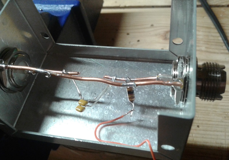 I built a temporary device to inject 12 VDC into the coax from the operating position. It doesn't get any simpler than this. I removed the resistor network from a QRP attenuator and soldered in a 0.2 μH capacitor and a 100 μH RF choke. A wires snakes around the sheet metal where it can be accessed.
To switch the antenna to north 12 VDC is applied between the chassis and wire. Polarity matters since the diode across the relay coil will short with the wrong polarity. I didn't bother with polarity protection for this temporary device.
The temporary switching system is ugly. The red clip lead is attached to the wire to point the antenna north. Two 9 volt batteries provide operating voltage of about 15 volts (one of the batteries is weak) which is well below the maximum voltage specification for the relay coils.

Some care is needed to avoid shorts. It is critical to get the cabling right otherwise DC will be injected into the receiver front end and that can be a very expensive mistake.
Performance
The first test was the SWR. When properly built and adjusted the impedance should be 75 + j0 Ω across a broad spectrum. Of course that ideal is never reached so it is fortunate that perfection isn't necessary for excellent RDF. Beverages are more forgiving antennas than driven vertical arrays.
This is very good! Some ripple of impedance versus frequency is typical. The flattening of the SWR at higher frequencies could be surge impedance variation with frequency or, more likely, due to increasing transmission line attenuation with frequency. The transmission line is approximately 150 meters of RG6 plus another 150 meters of RG6 in the south direction since that signal comes back to the feed point via the Beverage's RG6 span. Coax loss reduces signal level but does not affect the antenna pattern.
Signal level seems comparable to the 170 meter long northeast Beverage. A direct comparison isn't possible yet since there is no Beverage switching system. Theoretically the gain should be perhaps 1 db worse for north and 2 db worse for south. There is no need for amplification.
The biggest obstacle to listening tests was finding enough stations! Despite the pandemic confining hams to their homes the springtime decrease of low band activity is striking. North is always a problem since it is really only Asia in that direction and that is a difficult path at the best of times. To the south there is little activity in the Caribbean and South America and US station location cannot be determined from their call signs.
Despite that difficulty I cound enough stations to determine that the antenna does work, and it works well. To the north on 160 meters the main lobe is wide enough to show improved SNR on European signals and high rejection when pointed south. I found more Caribbean and South American activity on 80 and 40 meters, where the main lobe narrows, to give the antenna a good workout. However the very narrowness of the main lobe and the many minor lobes on 40 meter made comparisons a challenge.
All the South American activity I've monitored on 160 meters is FT8 so that's what I tested with. The evaluation was qualitative since signal strength readings in WSJT-X can be deceptive. Good signals from PY, LU and VP8 in the south direction disappeared or became too weak to decode in the north direction.
Comparisons on 80 and 40 to my yagis -- both of which have only modest F/B -- was very promising. The Beverage greatly improved SNR for stations to the south. Due to the narrow main lobe I wasn't able to find suitable stations to the north on those bands for make a definitive conclusion. I didn't get up early enough to look for east Asia activity (north direction).
Summing up
The antenna works to my expectations so I will continue with the rest of the Beverage plan. I will try to build the east-west reversible Beverage and the remote switch this month before the bush if full of ticks. It is possible to take protective measures but it is not worth the effort and risk. If I still have enough time the northeast Beverage will be "twinned" to make it reversible. What doesn't get done now I can continue in the fall.
The north-south Beverage has been disconnected and the feed line moved back to the northeast Beverage. Since I can only have one of the Beverages connected for the time being this is the one that is most useful. Soon the primary 160 meter transmit antenna will come down for the summer and my low band activity will slow considerably.
Next winter I will have a higher performance low band antenna system, both receive and transmit. I expect it to be well worth the time and effort invested.

Thursday, April 2, 2020
Beverage Site and Construction Plan
I am on course to install more Beverages and a switching system as my
preferred low band receive antennas. As I mentioned in my yearly plan I
was wavering on whether to use Beverages or vertical arrays. I have the
room to do either, which is not something many hams can claim. But
having the option requires that I make a choice.
Spring is not my preferred time of year to work on receive antenna. There are tower jobs waiting and I don't need low band antennas during the warm months when activity is elsewhere. The global pandemic lock down keeps friends away and I need helpers for most tower work. Therefore I am using the time to work on projects on the ground. Beverages are ideal.
In a coming article I will describe my next Beverage antenna, which is reversible north-south. Here I will revisit my site plan with respect to receive antennas and how I am proceeding.
Choosing Beverages
Beverages have the advantage of economy and simplicity. The construction of switching systems is not complicated so this work does not greatly effect other antenna projects. Since I enjoy designing and building antennas the choice of Beverages is a good one.
Beverages can be bi-directional, uni-directional or uni-directional and reversible. Reversible cuts down on cost and physical complexity at the price of electronics for switching and tuning. I chose reversible coaxial Beverage antennas as my path forward. That may change later if performance does not meet my objectives.
There are commercial products available for Beverages and vertical arrays. Beverage electronics are fairly simple and can be tackled by any ham. Vertical arrays are more complex. Commercial products take on the burden of vertical element phasing, combining and switching. None are inexpensive but are necessary for most. Many hams I know use them, or two for simultaneous independent use on two bands. These include receive triangles, 4-squares, 8-circles and BSEF arrays.
The improved directionality and therefore RDF (receiving directivity factor) of vertical arrays is good for DXing. All of the best vertical array have better RDF than single Beverages. For contesting a little "leakage" in other directions helps avoid missing many weak callers. That is, higher RDF can be detrimental in contests. So Beverages it is even though I have ample room for either.
Phased Beverages can equal the performance of many vertical arrays. In future I may experiment with these, in particular doubling the northeast Beverage to make an end fire array to Europe.
Site plan
Refer to my original site plan for this QTH and you'll see the large area of bush that I am using for receive antennas. Although working there is difficult for much of the year it has the advantages of being out of the way of farm equipment, suitably separated from other antennas and far from RFI sources.
I am making use of trees for many of the supports. Periodic brush clearing and the risk of damage by falling trees and branches is balanced by their convenience and almost zero cost. I must also site antennas to minimize damage from wildlife and occasional use of machinery in the area.
The northeast 170 meter long Beverage was installed a few years ago. It is unidirectional. My intention is to make it bidirectional, but not immediately. The antenna I am currently building is the north-south reversible Beverage running through the tree line between fields. Next will be the east-west reversible Beverage, possibly this spring or more likely in the fall.
The prospective northwest-southeast Beverage is lowest priority. Northwest is of limited use compared to the north Beverage. Southeast is far more important since it covers Africa and occasional skew path to Europe and other points. Similarly southwest is important for south-central US and the south Pacific. Unlike the higher bands I need good coverage of the US since the high noise level on 160 and 80 meters covers up many smaller stations I want to work in contests.
The switching system will be located near the west termination of the east-west Beverage. I have all the parts in hand to build it. Routing of the control cable will either parallel the transmission line or buried in a trench to the 150' tower where I have buried cable to the shack ready for use.
The transmission line follows the tree line west and then south to the Trylon tower adjacent to the house. This route minimizes coupling to the transmission lines of other antennas. It takes very little RF incursion to compromise RDF. For most hams this is not a problem since transmission and reception is rarely concurrent.
The bidirectional Beverages are 150 meters long. The RDF is almost as good as 175 meters and can be made from a 500' (152 meter) reel of inexpensive RG6. I don't want the main lobe to be too narrow since this can be problematic for contesting use. The antennas can be extended by simply adding more RG6 and moving the ground rods. Non-resonant antennas are nice that way.
Notes on Beverage siting
The placement of my Beverages is inspired by the experts. One is ON4UN and his indispensable book Low-Band DXing. If you care about the low bands you must have this book. You will learn not only the how but also the why.
The other is W8JI. His web site has a lot to say about Beverages and other receive antenna topics. ON4UN quotes from him extensively. While there are other reliable resources you won't go wrong with must these two.
Overlap: Beverage antenna can run right over each other without pattern distortion, provided the conductors don't touch. However the terminations should be at least 5 meters apart and 10 meters is preferable. Otherwise the impedance between their ground rods and radials may be low enough to allow signal incursion and therefore reduced RDF.
Height: Beverage gain increases with height although the maximum frequency at which they are useful decreases. My Beverages heights of 2 to 2.5 meters are a compromise between gain and good performance on 40 meters.The height allows for easy maintenance and reduced risk to and from deer, machinery and people.
Common mode: Grounds and chokes at critical points are required to eliminate common mode signals that can ruin RDF. Those points are the terminations, switching units and at intervals along transmission lines. This is especially important when a transmission line parallels a Beverage for more than a short distance. The easiest and cheapest choke that I like is a 1:1 balun on a ferrite core. If you require continuity for DC switching current on the transmission line an alternative is to wind the coax on a suitable ferrite toroid.
Length: RDF increases slowly with length (relative to wavelength). Although there are no magic lengths the minor lobes rise and fall as the length changes and can be chosen to maximize F/B or place pattern nulls towards a noise source. My Beverage lengths of 150 to 175 meters have a good RDF on 160 meters while not having too narrow a main lobe on 40 meters.
Proximity: The farther a receive antenna is from noise sources and transmit antennas the better. The area I've chosen for the Beverages is far from my house and very far from neighbours. The only potential problem area is the distance from the east-west Beverage and the 80 meter array radials. No degradation was noticed with a temporary 90 meter long Beverage so I probably won't have a problem the 150 meter long east-west Beverage.
Sharing: Should I ever choose to experiment with high RDF vertical arrays they can share the same field. Interaction issues are similar to overlapping Beverages. A good illustration of this is the receive antenna setup at W5ZN. The reason why receive antennas can coexist is their very low efficiency. The loss resistance (small size, ground loss, etc.) greatly reduces mutual impedance.
Next steps
The north-south Beverage antenna has been installed and it is working well. Testing will continue to determine how well. In the absence of a switching system the coax to the northeast Beverage was temporarily moved to the new antenna for testing. DC is injected into the coax to switch directions. Expect an article on this antenna soon.
If the pandemic situation continues and help for the big jobs is unavailable I will work on the switching system and shack controller. With more delay I might also install the east-west Beverage. All of this work must cease by May to avoid the start of tick season in the dense bush. I really don't enjoy that.
Within a month I may have a 5-direction highly effective receive antenna system. Summer is not when it's most useful but during the current crisis you do what you can.
Spring is not my preferred time of year to work on receive antenna. There are tower jobs waiting and I don't need low band antennas during the warm months when activity is elsewhere. The global pandemic lock down keeps friends away and I need helpers for most tower work. Therefore I am using the time to work on projects on the ground. Beverages are ideal.
In a coming article I will describe my next Beverage antenna, which is reversible north-south. Here I will revisit my site plan with respect to receive antennas and how I am proceeding.
Choosing Beverages
Beverages have the advantage of economy and simplicity. The construction of switching systems is not complicated so this work does not greatly effect other antenna projects. Since I enjoy designing and building antennas the choice of Beverages is a good one.
Beverages can be bi-directional, uni-directional or uni-directional and reversible. Reversible cuts down on cost and physical complexity at the price of electronics for switching and tuning. I chose reversible coaxial Beverage antennas as my path forward. That may change later if performance does not meet my objectives.
There are commercial products available for Beverages and vertical arrays. Beverage electronics are fairly simple and can be tackled by any ham. Vertical arrays are more complex. Commercial products take on the burden of vertical element phasing, combining and switching. None are inexpensive but are necessary for most. Many hams I know use them, or two for simultaneous independent use on two bands. These include receive triangles, 4-squares, 8-circles and BSEF arrays.
The improved directionality and therefore RDF (receiving directivity factor) of vertical arrays is good for DXing. All of the best vertical array have better RDF than single Beverages. For contesting a little "leakage" in other directions helps avoid missing many weak callers. That is, higher RDF can be detrimental in contests. So Beverages it is even though I have ample room for either.
Phased Beverages can equal the performance of many vertical arrays. In future I may experiment with these, in particular doubling the northeast Beverage to make an end fire array to Europe.
Site plan
Refer to my original site plan for this QTH and you'll see the large area of bush that I am using for receive antennas. Although working there is difficult for much of the year it has the advantages of being out of the way of farm equipment, suitably separated from other antennas and far from RFI sources.
I am making use of trees for many of the supports. Periodic brush clearing and the risk of damage by falling trees and branches is balanced by their convenience and almost zero cost. I must also site antennas to minimize damage from wildlife and occasional use of machinery in the area.
 |
| Satellite image from Google Maps |
The northeast 170 meter long Beverage was installed a few years ago. It is unidirectional. My intention is to make it bidirectional, but not immediately. The antenna I am currently building is the north-south reversible Beverage running through the tree line between fields. Next will be the east-west reversible Beverage, possibly this spring or more likely in the fall.
The prospective northwest-southeast Beverage is lowest priority. Northwest is of limited use compared to the north Beverage. Southeast is far more important since it covers Africa and occasional skew path to Europe and other points. Similarly southwest is important for south-central US and the south Pacific. Unlike the higher bands I need good coverage of the US since the high noise level on 160 and 80 meters covers up many smaller stations I want to work in contests.
The switching system will be located near the west termination of the east-west Beverage. I have all the parts in hand to build it. Routing of the control cable will either parallel the transmission line or buried in a trench to the 150' tower where I have buried cable to the shack ready for use.
The transmission line follows the tree line west and then south to the Trylon tower adjacent to the house. This route minimizes coupling to the transmission lines of other antennas. It takes very little RF incursion to compromise RDF. For most hams this is not a problem since transmission and reception is rarely concurrent.
The bidirectional Beverages are 150 meters long. The RDF is almost as good as 175 meters and can be made from a 500' (152 meter) reel of inexpensive RG6. I don't want the main lobe to be too narrow since this can be problematic for contesting use. The antennas can be extended by simply adding more RG6 and moving the ground rods. Non-resonant antennas are nice that way.
Notes on Beverage siting
The placement of my Beverages is inspired by the experts. One is ON4UN and his indispensable book Low-Band DXing. If you care about the low bands you must have this book. You will learn not only the how but also the why.
The other is W8JI. His web site has a lot to say about Beverages and other receive antenna topics. ON4UN quotes from him extensively. While there are other reliable resources you won't go wrong with must these two.
Overlap: Beverage antenna can run right over each other without pattern distortion, provided the conductors don't touch. However the terminations should be at least 5 meters apart and 10 meters is preferable. Otherwise the impedance between their ground rods and radials may be low enough to allow signal incursion and therefore reduced RDF.
Height: Beverage gain increases with height although the maximum frequency at which they are useful decreases. My Beverages heights of 2 to 2.5 meters are a compromise between gain and good performance on 40 meters.The height allows for easy maintenance and reduced risk to and from deer, machinery and people.
Common mode: Grounds and chokes at critical points are required to eliminate common mode signals that can ruin RDF. Those points are the terminations, switching units and at intervals along transmission lines. This is especially important when a transmission line parallels a Beverage for more than a short distance. The easiest and cheapest choke that I like is a 1:1 balun on a ferrite core. If you require continuity for DC switching current on the transmission line an alternative is to wind the coax on a suitable ferrite toroid.
Length: RDF increases slowly with length (relative to wavelength). Although there are no magic lengths the minor lobes rise and fall as the length changes and can be chosen to maximize F/B or place pattern nulls towards a noise source. My Beverage lengths of 150 to 175 meters have a good RDF on 160 meters while not having too narrow a main lobe on 40 meters.
Proximity: The farther a receive antenna is from noise sources and transmit antennas the better. The area I've chosen for the Beverages is far from my house and very far from neighbours. The only potential problem area is the distance from the east-west Beverage and the 80 meter array radials. No degradation was noticed with a temporary 90 meter long Beverage so I probably won't have a problem the 150 meter long east-west Beverage.
Sharing: Should I ever choose to experiment with high RDF vertical arrays they can share the same field. Interaction issues are similar to overlapping Beverages. A good illustration of this is the receive antenna setup at W5ZN. The reason why receive antennas can coexist is their very low efficiency. The loss resistance (small size, ground loss, etc.) greatly reduces mutual impedance.
Next steps
The north-south Beverage antenna has been installed and it is working well. Testing will continue to determine how well. In the absence of a switching system the coax to the northeast Beverage was temporarily moved to the new antenna for testing. DC is injected into the coax to switch directions. Expect an article on this antenna soon.
If the pandemic situation continues and help for the big jobs is unavailable I will work on the switching system and shack controller. With more delay I might also install the east-west Beverage. All of this work must cease by May to avoid the start of tick season in the dense bush. I really don't enjoy that.
Within a month I may have a 5-direction highly effective receive antenna system. Summer is not when it's most useful but during the current crisis you do what you can.
Subscribe to:
Posts (Atom)