Saturday, November 26, 2016

W1AW/p Centenary WAS

Earlier this month the VA3/VE3 incoming QSL bureau notified me that I had a lot of cards to be mailed out and to please sends funds since this would blow through my previous deposit. I was a little surprised by this influx of cards since it seemed unusual. Nevertheless I forwarded the funds and my mailbox was soon filled by several heavy envelopes.

More than half of the cards were for the 2014 ARRL centenary celebration stations W1AW/p operating from every US state and overseas territories. I guess they had lots of cards printed and decided to confirm every QSO, even without any requests.

I do not as a rule apply for operating awards of any kind, not even DXCC, being happy to have worked the stations I want to work without requiring any more paper. This is why I was pleased to sign up for LOTW to escape paperwork, and especially unwanted task of filling out QSL cards.

Nevertheless my curiosity was piqued. In 2014 I was operating QRP with my KX3 and for the most part using simple wire antennas. I was certain I had worked all 50 states worth of W1AW/p stations just by habit of jumping in when I stumbled across them. It seems that being a DXer I am loathe to bypass any pile-up!

And so it seems I did indeed work all 50 states. Now they're confirmed (many twice) as well as most of the overseas territories. No, I am not curious enough to break it down by band! But I do know it was all CW.

Although the award itself does not interest me these cards make a nice memento. Kudos to ARRL for doing this.

Saturday, November 19, 2016

Planting the Trylon Tower

In the previous article I discussed forming and installation of the rebar cage for the foundation of my Trylon Titan T400 tower, nominally 72' tall. I am using this project as a vehicle to describe some of the important skills and activities involved in erecting a reasonably large self-supporting tower. This article will take us through to the concrete work, completing the planting of the tower.

It is my hope that hams who have never put up a tower with a concrete foundation, or even those who have, will learn something and perhaps gain motivation to take on a project of this size. Certainly I have learned new skills, including rebar form construction, and it's fun to pass that along to others. Ham radio is a fantastic opportunity to learn new skills and it would be unfortunate to avoid those opportunities by hiring someone to do it or going without.

Eventually I'll get back to antennas and operating. Since every antenna needs a support structure this long sidetrack is, in my opinion, well worth the time. I hope that readers will agree.

With that out of the way let's plant that tower in the ground. All the work up to this point will finally show tangible results.

Alternatives to positioning and securing the tower base

The base section and anchor stubs for the majority of towers of this type (typical for ham use) must hang rigidly suspended over the foundation excavation for the pouring of the concrete. Since magical levitation isn't an option we need a practical approach. There are a few objectives:
  • Position the tower, laterally and vertically, per the manufacturer's specification.
  • Support the weight of the tower without sag, movement or risk of tipping or other failure mode.
  • Cheap and effective, but not necessarily pretty.
  • Can be built and the tower placed by muscle alone.
  • Withstand the force of concrete pouring from a height and lateral flow.
  • Rapid adjustment of tower position, lateral or vertical angle, if and when concrete or other force shifts it.
  • Does not impede pouring of the concrete, whether by chute or wheelbarrow.
This is a long list! I have seen many systems, both good and bad, devised by hams over the years. Professionals have their own favourites. Here are the ones I am most familiar with:
  • Chairs: Concrete blocks -- they must be concrete -- are positioned at the bottom of the hole. The base section and stubs sit directly on those blocks. The base section must be guyed top and bottom to prevent movement and collapse of the chairs while the concrete is poured. From asking around this is option chosen by many hams with Trylon towers.
  • Side bracket: This method is only possible when the tower is next to a rigid structure. Enough tower is built (usually one or two) sections to allow bracketing to the adjacent structure. In this way the tower is suspended over the hole and held rigid. It is guyed or otherwise secured just above ground level. After the concrete sets the bracket and guys are removed.
  • Scaffold; Two or three lengths of lumber, steel or other rigid and strong material pierce the base section near ground level so that the horizontal or diagonal cross members between legs rest on them. These are in turn supported at either end so that the tower is correctly positioned. The scaffold should be clamped to the tower for best results. Top guys may be required.
  • Cradle: A steel or lumber cradle is built on the base section. The cradle is wider than the tower and rigidly attached. It is then carried or lifted by muscle or machine over the hole and supported at all corners. Top guys are not required.
In my situation a side bracket is not an option and chairs require at least 3 people for a tower of this size. Even a scaffold is difficult to install with fewer than two people. This is impractical for the Trylon Titan series since all the cross members are diagonals that would require 3 supports rather than just two.

A cradle is more elaborate but it only requires one person to do all the work. Also, since I've never built a cradle before that's what I decided to proceed with. I came up with a design that would work for the Trylon and bought the lumber I needed. Pretty much all the hardware was acquired from my junk box.

Cradle

Picture from an earlier article included for convenience
Unlike a scaffold a cradle is mechanically integrated with the base section. Its purpose is to suspend and secure the base section and stubs over the hole and to facilitate lifting the assembly upright into the hole. This is no simple task since the #12 section and stubs weigh in excess of 200 lb (90 kg) and the design of the Trylon tower diagonals makes attachment awkward. The cradle itself adds approximately 30 lb (14 kg). I had strong doubts whether I could manage the job by myself.

The cradle was built onto the #12 section with it lying on the ground and the stubs on the bottom legs resting on the hole casing. The construction of the cradle is captured below in a mosaic of views. The large picture on the left shows the tower immediately following lifting onto the skids and centred. The rear stub is not attached since it would strike the casing when the tower is levered upright due to its large turning radius. Draw it on a piece of paper and you'll see why that is so.


The remaining picture shows details of the cradle design and truing technique (next section). The front of the cradle consists of two lengths of 2x6 lumber, the inner one cut to fit inside the tower face and the outer one long enough to rest on the skids (2x4 nailed to two sides of the casing). The inner one butts up against the lowest diagonal on two sides, clamping the tower face between them. Scrap angle steel provides a hard surface for the diagonals to rest on to ensure they don't cut into the lumber.

The skids are worth a further look. These lengths of 2x4 on opposite sides of the casing serve multiple purposes. First, the keep the casing square by preventing any twisting. Second, the cradle is above the top of the foundation so that it cannot touch the wet concrete. Third, the wider surface is better for placement of shims to true the tower (next section).

The rear of the cradle is a single length of 2x6 lumber clamped to the tower leg with copper-plated steel strapping (it's what I had on hand). The choice of 2x6 lumber was determined by measuring the distance from the leg bottom to the supporting diagonals and adding the height of the 2x4 skids so that the manufacturer spec of 1" between the leg bottoms and concrete surface is met.

With everything done I manhandled the ridiculously heavy assembly until the front cradle was just past the edge of the rebar cage. There is little clearance so I had to get this right. I next adjusted the cradle's lateral position by eye so that the ends of the stubs were square to the hole. Otherwise one of the stubs will crash into the rebar cage when the assembly is rotated upward. That would be very bad.

Pushing up on the top tower leg I kicked a milk crate under the diagonal closest to my feet. That makes it easier to lift by giving lots of finger room underneath the tower. But here I experienced something unexpected: it was remarkably easy to lift the tower. The weight of the stubs and much of the cradle counterbalanced a significant portion of the 170 lb #12 section.

As it turned out I could have lifted the section with just one arm, rather than doing a power lift. The step in the operation I was most worried about turned out to be the easiest. I think I had a silly grin on my face as I lightly pushed the tower upright in a few seconds, even holding it up halfway while I ensured the position of the stubs was where they needed to be. What was to be a simple test of the cradle before I got on the phone to call up a friend to drive out to my place turned into the actual lifting. Lots can go wrong in tower work so it was pleasant to have this turn out so well.

The last task is to attach that last stub. I loosened both straps and inserted bolts into the two holes not covered by the straps. One at a time I lifted one side of each strap to insert the other bolts. This reduced the risk of the cradle slipping out. With the straps back in place but loose I dropped into the hole to attach the lock washers and nuts and tightened them.

Truing the tower

When I installed the casing for the tower foundation I got it almost but not quite level. With more fussing around with shaving dirt here and there I could have gotten it near perfect. But there is no need since even with the best of intentions there will be a problem elsewhere. In particular with the positioning system for the tower base over the hole. Such was the case with my cradle.

Truing the tower is the process of having it exactly vertical. With the cradle in place I had only to adjust it with shims. Although the cradle front and rear both used 2x6 lumber butting against the bottomost diagonal cross member the rear end used the bottom (vertical) of the L-shaped diagonal and the front used the top (horizontal). That is enough error for about the thickness of a lumber stud (less than 2").

As a result the rear leg sits higher on the skids than the front. Since it cannot be lowered the shims must go on the front. You can see them in the photo mosaic above.

For measurement I used a long carpenter's level. On towers with straight sections it is a simple matter to place the level along the vertical legs and ensure they are indeed vertical. On a tapered tower, which is typical for self-supporting towers, the legs are not vertical when the tower is vertical. The tower manufacturer often recommends taping a spacer at a prescribed position on the level as compensation for the taper.

My preferred techique is instead to aim for an equal error on all 3 legs. There is no spacer to make or attach (and lose). I learned this from another ham so far in the past I can't remember who it was. It's the method I always use and it has never failed me. However, there are things to watch out for:
  • Not all levels are properly calibrated. For this reason always use the same edge of the level to measure all the legs. It's a surprisingly common problem.
  • Wipe the level and tower legs since it takes only a small amount of dirt to skew the level.
  • Tower legs are not as perfectly straight as you might expect. This is especially true on towers with bent sheet metal legs such as the Trylon. When the level is against the tower leg you should not see any gap between them. If there is a gap move the level to a better position. The leg vertex is a better choice than one of the sides even though it is more difficult to set the level properly on it.
Securing the assembly

Secured, vertical and ready for concrete
One of the joys of a cradel is that the tower base is exceptionally stable against forces that would shift its position, either by accident of the flowing concrete. Other supports may not do as well. Of greater concern to me was the rebar cage.

With the tower in position and trued I dropped into the hole and wired each leg to the rebar cage in two directions. I then removed the temporary lumber spacers between the rebar cage and the hole walls. The rebar shifted a small amount which I adjusted by tightening the wires. Although the rebar cage weighs as much as the base section plus stubs the tower does not shift since it has the advantage of leverage.

Affix temporary guy wires to the top of the base section so that the tower can be adjusted back to vertical during the concrete work if tilts off vertical. Although the cradle was solid enough that I didn't expect to use them (and I didn't) I had them ready just in case.

Now, finally, it is time to call the concrete company.

Concrete work

In contrast to the step to this point the pouring of concrete goes fast. Perhaps too fast if you don't call a pause at sensible intervals. You usually have time since (here at least) for a given quantity of concrete you have the truck at your disposal for a set period of time. Only if you go beyond that will extra charges apply. That is unlikely to happen unless you are transported the concrete by wheelbarrow. (Someone did take a few pictures during the pour but I don't have them so there are none included here.)

Find out the required concrete strength from the tower specification. It is typically not an ultimate strength but that achieved after 28 days of curing in "normal" conditions. The Trylon requires 3,000 psi so I ordered 6 yd³ of 3,500 psi as a safety margin. Actually it was 4.6 m³ of 25 Mpa concrete since most business in Canada is conducted in metric. The truck of ready-mix arrives the same afternoon, after a wait because the driver got lost for a while (even locals occasionally have trouble finding this isolated QTH).

My preparation for the truck was quite simple. I called a friend to lend a pair of experienced eyes to the proceedings. This is very helpful since everything happens fast. Second, I cleared a path so the truck could easily back up right to the tower.

This brings up an important point: do you know where all your buried services are located? The truck is very, very heavy and can do a lot of damage. In the city the driver will often ask is there are any buried services he's being asked to drive over, and may insist you sign a waiver absolving the company if there is damage. Out in the country it can be different; our driver didn't ask. However I knew exactly what was where. Make certain you know.

Talk to the driver. Explain what you're trying to achieve. I told him I needed good flow to fill the flare at the bottom of the hole and to fully encase the chairs and rebar. A rented concrete vibrator can help, if you are willing to go to the bother and expense. I never have. You can achieve a lot by pumping a shovel up and down in the concrete and the driver adding some water to the mix. The small amount of added water slows the curing but does not weaken its ultimate strength.

Concrete is heavy and it is falling from a substantial height. Make sure the chute is positioned to miss the tower structure and rebar. The driver for my pour was careful and helpful. Concrete splashes so don't wear your best clothes! Cleaning your clothes is far easier when you wait for the stains to dry.

Keep an eye on things. Tell the driver to slow down when nearing the desired level. Many in the business talk of concrete being self levelling. Don't believe it. Use that shovel to move the concrete around, especially the voids behind the rebar. When the hole is full ensure there are no voids at the base stubs. Voids are typical where metal pierces the concrete and they are easily overlooked.

Adjusting the true of the tower during the pour can be a problem if you are unprepared. If you've attached those temporary guys that I mentioned earlier you're part way there. You have to do it quickly when necessary since, as I've said thing move fast during the pour. It can help to have a tensioner for the guys that is quick and easy to adjust. Look at the adjacent picture (and try not to laugh).

The guy is tensioned by adding or removing stones from the plastic crate that is attached to the rope guy mid span. This is far quicker than untying and tying knots or a turnbuckle. Silly but very effective. For the other guys (not shown) one is the #11 section (150 lb), which is moved back and forth to change the tension, and the other is a plank over the guy to which stone or bricks are added and removed. Again, silly and yet effective. Your friends may smirk and question your sanity but only until they see how fast you can true the tower.

The screw and chute have to be cleaned after the pour. Pick a good spot in advance for the driver to do this. They usually ask, but not always. It can be messy.

If you want a smooth finish mist the concrete and go to work with a trowel. Don't delay or it'll be too late. Do not clean the concrete on the tower, cradle, casing or elsewhere on the assembly until it dries. Should you try it when the concrete is liquid you'll only damage the surface of the foundation.

Shades of Cool Hand Luke

Digging a hole and filling it in again has been used as an instrument of torture. You may remember the scene in the movie Cool Hand Luke where the sadistic warden does this to Luke. In our case it isn't torture although there may be mixed feelings as you watch the hole fill with concrete. A lot of work went into the planning, digging and the rebar cage.

Relax and don't fret! Once the tower is standing proud and your yagis are singing and dancing on the bands you'll forget all about it. That is, until the next tower project.

Waiting and preparing

Keep the exposed concrete damp. Experts agree that hydration speeds curing and can increase the ultimate strength. If the temperature approaches or dips below freezing it's a good idea to cover the concrete with plastic or other covering that inhibits evaporation and ice formation.


The casing can be removed as soon as the next day. I like to leave it be for two days. Since I had to be away I did it the third day. For those who like a tidy look to the concrete you can use a cold chisel to remove ridges and other protrusions.  Do not use a file since aggregate in the concrete (such as sand) can quickly ruin the file . Once you're happy with it you should restore the lawn around the tower to appease spouse and neighbours. Appearances matter.

After removing the casing I applied a fast-drying concrete repair compound to fill the voids I missed on the inside of the stubs (note the wet spot in the picture above). The cradle made it difficult to do properly while the concrete was being poured. You can use the compound to build a shallow slope so that water flows away from the legs. Pooling water over the years can initiate corrosion.

Now is a good time to call your friends to arrange a tower raising party. Borrow or build a gin pole and do other tasks to prepare. You'll want everything in place so that no time is wasted when the time comes.

I would wait at least 7 days before constructing the tower. There is really no need to delay longer since by then the concrete is sufficiently cured for all but the most severe weather with a heavy antenna load. Concrete curing is a long-term process with no definite date when it stops strengthening.

As I write these words several days of snow are forecast. There will be a delay.

Sunday, November 13, 2016

Reinforced Concrete: Rebar for Towers

Concrete is basically man-made rock. Rock is strong in compression and weak in tension. That is, it makes strong columns and weak beams. This is why, for example, ancient Greek and Roman architecture had so many columns filling open spaces in their buildings: it was only those short spans that allowed the beams to support roof and floor loads, including their own massive weight.

The integration of steel into manufactured concrete building components corrected this limitation. The steel enables concrete to remarkably increase its tension capacity. We see this in bridge spans, office building floor slabs and even in our garage floors and house footings. Reinforced concrete is a major component in all but the smallest towers we use in amateur radio.

There is substantial tension present in self-supporting towers when faced with a strong wind and in the guy anchors and bases of guyed towers. So when we dream of big towers and big antennas we need to reinforce concrete.

Rebar

Steel rebar (reinforcement bar) is specified in the foundations of towers and guy anchors by the tower manufacturers to meet the engineering requirements for their products to support themselves, the loads (antennas) and couple those loads to ground. Rebar is not an option, so we need to do it right.

I ordered over 1,000' (300 meters) for rebar of various sizes to include in my Trylon self-supporting tower, the LR20 guyed tower and extra to get me started on a third tower. For these big orders go with an industrial supplier since their prices are far lower than the retail outlets, including the big box stores, and delivery is often free or they charge a nominal amount.

The amount required can be surprisingly large. For the Trylon #12 base section foundation I needed 200' of rebar: 20x5' verticals and 5x20' ties. The weight is substantial, coming in at ~200 lb (90 kg).

These are convenient lengths since rebar in Canada and the US the standard length is 20', even for the metric sizes we use in Canada. Where US rebar sizes are specified the tower manufacturers recommend rounding up to the next largest metric size.

Cutting rebar

Small diameter rebar used for ties can be cut to length with bolt cutters. Since the largest bolt cutters I have have a ⅜" capacity (up to #3 rebar) that was not an option. A hacksaw is too slow and tedious for the amount of cutting I needed to do. This is a job for power equipment. My tool of choice for cutting rebar is a circular saw with a 7" steel cut-off (abrasive) disk. A cut-off saw with an abrasive disk is easier and more accurate if you happen to have one.

Cutting steel this way can be dangerous when not done properly. The steel that is thrown off by the tool is a fast, dense stream of hot particles accompanied by metal vapour. Skin, eye and breathing protection is required. If you are feeling lucky the last can be omitted if done outdoors and the wind is at your back. The rebar will be very hot following cutting so do not touch it anywhere near the cut and use thick gloves of natural fibre such as cotton. Toss it aside to cool while you move on to the next cut.

I lay out several scraps of lumber on the ground to support the full length of the rebar and both sides of the cut. The end of the measured length of rebar butts against an immovable object to avoid errors due to inadvertent movement. My booted foot presses down on the other side of the cut as the tool does its work. Cut straight and keep some pressure on the steel for maximum safety and speed.

To reduce waste I did not cut each 20' length of 20M rebar into 5' lengths. I cut one 5' length for a Trylon vertical and cut the remaining 15' into two 7.5' lengths for the LR20 anchors. Thus there is no waste. I need 21 of those for the 3 anchors. I now have 19 in storage for a future guyed tower of similar size. If you do have waste it can be used for surveying stakes, supporting tree saplings or other jobs around the house.

Tools to bend rebar

Readily available tools to bend rebar include hand tools, mechanical benders and hydraulic benders. The latter two are expensive for the modest amount of rebar bending that the typical ham will need. Hand tools are far cheaper but are not well suited to making bends of the required radius, angle and position, and their capacity is typically limited to #5 rebar. Searching the internet for advice turns up far too many useless techniques that are either too ad hoc or require expensive equipment. I needed a better way.

I have never bent rebar before. This is perhaps surprising since I've put up so many towers over the years. In the past, where rebar was involved, it was done by someone else and all I had to do was make sure it was in position and guide the pouring of concrete. So this project was also a learning experience for me.


I purchased a "hickey" bending tool by mail order. As you can see it is basically a snipe with hardened steel pegs to hold and bend the rebar. The typical application of a hickey is hold the rebar against a hard surface with your foot (stiff boot) and pull up. I did an experiment to see how this would work out. I wrapped the bend area with masking tape, marked the pins with a pencil to see where the rebar would bend in relation to the tool.

It was not a happy experience. The leverage was enough to lift me off the ground and the resulting bend radius was far too large. The ties for the Trylon cage need a much sharper bend (small bend radius). For the time being I tossed the hickey aside to reconsider how I'd bend the ties and turned to attack the 20M verticals. These are too large for a hickey in any case so I designed my own tool.

Two trees and 3 pipes

20M rebar (slightly larger than #6) is not easy to bend without mechanical assistance. The substantial leverage required is difficult to achieve with hand tools and readily available supports. But where there's a will there's a way, with a little ingenuity.

The 20 verticals in the Trylon rebar cage require a hook to match the flare at the bottom of the foundation (see Trylon drawing above). Although perfection isn't mandatory we want to get close so that the flare area doesn't crack when the tower is subjected to extreme load. So don't skip this task because it seems too difficult.

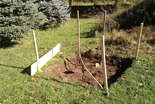
The simple jig I constructed required two small trees near to each other and enough room to swing a 10' pipe acting as a snipe. The picture shows the large picture subsequent to bending one of the 20M verticals. If you study the picture I expect you can discern how the jig works. A close up of the bend zone is in the next picture.


Both pipes are 1.5" schedule 40 water pipe. Graded steel isn't necessary. Inside one pipe is a 2' length of ¾" pipe whose inner diameter is slightly greater than the 20M rebar (19.5 mm). That inner sleeve ensures that above the desired bend zone the rebar doesn't get bent. To get the 12" from the bend zone to the bottom I measured 13" (leaves partially hides the rebar) and carefully position the movable pipe just less than 1" from the fixed pipe.

In action the movable pipe is moved right until the rebar is locked by friction and gripped by the trees. Then the movable pipe is pulled, hard, until it taps the barrel. By happenstance the barrel is perfectly positioned to achieve the desired bend angle.

Once I got the jig built and tested the bending of the verticals was very quick. All 20 20M verticals were done in 35 minutes. Stacked together they make a pretty sight. They are almost exactly identical.

With the verticals done I returned to the problem of forming the ties. Unhappy with the action of the hickey alone I built a jig to hold to hold the smaller rebar and provide a hard edge for the hickey to work against. As it turned out there was a piece of steel mounted to one of the LR20 sections that appeared ideal for my purpose.

The angle steel is ¼" thick and attached to a tower girt with ⅜" bolts. It served as a bracket for a side-mounted yagi (and may yet again). To grip the rebar I installed ⅜" bolts with two ½" nuts serving as the surface for holding the rebar. All hardware is grade 5. The tower section is sandwiched between other sections to hold the jig during the bending. Even at 120 lb per section I periodically had to reassemble the sandwich. That's a lot of torque!

As in my previous attempt I covered the bend area with masking tape and marked all the key points. The forward (closest to the jig) pin on the jig was positioned about ½" from the edge of the angle steel. The test bend turned out perfectly. I measured the distance from the jig to the outside of the bent rebar to determine how to position the rebar for the tie formation.

I made two bends in this fashion then flipped over the rebar and did the final two bends from the other end. This way most of the rebar's weight and length does not have to be supported while bending. It's important to get the sides the correct length, square and in a plane. Get it wrong and it'll be difficult to correct, as I discovered. Don't waste 20' of rebar due to carelessness.

The result is quite good. The tie sides are 53" (outside edges), which is 7" less than the hole's sides. Rebar should be no closer than 3" from the sides of the concrete form or there is risk of moisture incursion which can crack the concrete and corrode the rebar after several years. I added an extra 1" margin.

Building the rebar "cage"

Professionals build the rebar cage above ground, in a jig, then transport it to the tower site and place it in the hole. I considered doing it that way until I realized that the rebar cage would weigh close to 200 lb (90 kg). That's a two man job and I didn't want to inconvenience anyone else. Besides which I don't have a jig and didn't want to build one.

Since the hole is, of course, almost exactly the precise shape required I used that instead of a jig. By building it in place I avoided having to carry it and, somehow, lowering it into the hole. But it did mean several hours spent sitting in a hole in the ground!

To begin I dropped all 5 ties and 4 verticals into the hole. In the hole I lifted the top one, resting one side on a ladder (the one I used to get in and out of the hole). With that as support I wired the opposite corners to two verticals leaning against the sides of the hole. Then I did the ones by the ladder. The ladder had to be removed since it wasn't quite the correct height. I did the remaining ties much the same way, working from the top to the bottom. After the second tie was in place the 4 verticals were stable enough to hold the partially-complete cage.

For my tower (see the #12 foundation detail above) the ties are ~12" apart. The verticals are ~10.5" apart on average. Precision isn't critical, but utter sloppiness must be avoided. Don't fret over minor inequalities in the spacing.

All the crossings are wired for the first 4 verticals and the ties. The remaining 16 verticals do not require 100% coverage. I wired all of them at the top and bottom ties. For the remaining 3 ties I alternated one wired crossing (middle tie) and two wired crossings. Never skip two crossings in a row.

My wiring technique was sloppy at first. It got better. I used steel rebar wire (very cheap and widely available). Using pliers I followed the common wiring techniques I discovered on the internet. It is important to ensure the crossing rebars are pulled tight against each other so that the corrugations lock them together. These connections only need to survive the pouring of the concrete since they are not mechanically needed after the concrete has set.

Since some of my bends were imperfect a few of the verticals needed to be repositioned so that all the crossings had good contact. Squeezing them together by hand isn't always possible or advisable.

When I was done I was pleased to find that I achieved the requisite 3" spacing from all 4 walls of the hole. There were a few spots where I had to shave some dirt off the walls to get it right.

There are lots of crossings so take the time to check them all. Don't skip this step or the foundation can develop cracks in a few years due to water incursion and corrosion.

As you can see in the picture the rebar cage is not perfectly rigid. Each side has some play since the wired crossings don't fully lock the rebar. For that you'd need to spot weld the rebar. I lifted the rebar verticals from the bottom to move the cage in small steps until the bottom tie was the correct distance from all the hole walls. Scrap lumber wedged between the tops of the verticals and the walls temporarily squared the cage. In this way I confirmed the dimensions were correct for the entire cage. The props were removed for the next step.

Rebar chairs

Rebar cannot sit on the ground. Like the rest of the rebar they must be separated at least 3". This requires what are called rebar chairs. These can be as simple as concrete blocks, although there are commercially available chairs made of plastic and concrete. Concrete chairs have protruding wires so they can be attached to the rebar. Do not use stone, wood or other random material since they will decay or fail to bond with the concrete.

Since plastic is a poor choice for a cage of this weight, are difficult to get the concrete into during the pour, and I couldn't easily find proper concrete chairs, I went with concrete bricks. I found a suitable product at a local brick factory I was directed to by a contractor working on my house. Placed on their sides they are 3.5" tall, which is perfect. They were also unbelievably cheap. Do not use clay brick!

Not every vertical needs a chair. Use enough to ensure the chairs can hold the cage without sag or shifting of the cage. I used less than 10 bricks. Add or shave dirt under the bricks as needed to keep the cage level and all them taking their share of the weight.

Securing the cage

If you look closely at the previous picture you can see a tower stub sneaking into the frame. Clearly my pictures are not quite in chronological order. However it is useful for this next step.

The #12 section base stubs clear the inside of the rebar cage by only a few inches. The sides of the cage are ~53" on the outside and less than 51" on the inside. The stubs on the #12 tower section flare out to almost 46", leaving a gap as small as 2.5" (8 cm). It was therefore necessary to reinstall the temporary lumber blocks at the top of the cage when the base section and stubs were manoeuvred over the hole.

With the tower and stubs in position per the manufacturer's drawings I wired the stubs to the rebar cage. The tower section with stubs weighs close to 200 lb (90 kg) so pulling the wire tight did not shift it. The lumber blocks kept the rebar cage from shifting while I tightened the wires. I made sure there was good tension in all directions and removed the blocks. Some adjustment of the wires ensured that the tower and cage were in position and stable against moderate force.

In the next article I'll back up a step to show how I suspended the tower base section over the hole. That deserves an article of its own.

Cleaning up

When you're all done there is one more small task to perform. It is a good idea to use a steel wire brush to remove surface rust on the rebar and to remove any mud and dirt clinging to the rebar. Even newly delivered rebar will have some rust on it since steel readily oxidizes. Rust will weaken the bond with the concrete. Although a little bit of rust is not a problem cleaning takes only a few minutes. Not all the rust will come off and it needn't.

Mud and dirt will block concrete from reaching the rebar and can be a greater problem than rust. Dirt from the walls will find its way into the gaps where rebar crosses, whether tied or not, from banging and dragging against the sides of the hole during construction and positioning of the rebar cage. If the wire brush can't get into these small spaces use something smaller.

Monday, November 7, 2016

Digging a Hole for a Tower Foundation

You've selected a site for your tower, dealt with the legalities and the time has come to stick a shovel in the ground. What's the first thing you need to think about? It probably isn't what you might guess.

Debris removal

The base of the Trylon tower I am putting up requires 6 yd³ of reinforced concrete. Of course that means digging a hole that will displace the same amount of soil. That's a lot of dirt and rock! Where will you put it? How will it get there? You cannot easily hide that much on a typical suburban lot.

If you don't already have one, borrow or buy a wheelbarrow. Mine has a rated capacity of 6 ft³, which is not quite ¼ of a yd³ (27 ft³). In reality you will not and should not approach the rated capacity; 3 to 4 ft³ is the limit for safety and what the average, healthy person can handle. In other words, about 50 wheelbarrow loads.

The topsoil you will start with has some value. Put it in your garden or offer it to your neighbours. Unfortunately that will rarely amount to more than 2 yd³. Below that you will encounter rock, sand or clay, or some mixture of them. Putting up a sign on your lawn offering "Free Clean Fill" is unlikely to make the problem disappear.

On my rural property I have many available solutions to this problem. The stonier soil has gone to repair the ruts on my 100 meter long driveway. The soil will be used to fill low spots on the lawn. The large stones will go to the stone wall or will be used as paving stones when I get around to doing landscaping around the house.

I am fortunate. Chances are you are not. So think very carefully before you start digging.

Excavation alternatives to consider

Picking up a shovel and having at it is one way to dig a hole. Although it is hard physical labour it comes with a certain sense of accomplishment. One benefit is that you do it on your own time, when and how you want. Buy some refreshments and invite over your strongest ham buddies and you've got a social event!

Digging may seem simple but it comes with risks. If you are in poor physical condition or if you don't know your limitations or you use poor technique you can injury yourself. Mistakes multiply when you're tired. Take frequent breaks and know when to call for assistance if you're in over your head. Don't be stubborn where your health and safety are concerned. There are ample references to consult on tools and tool use so I will not give a tutorial on safe, efficient digging technique.

The second alternative is the same but with hired help. I'll bet that you, like me, know a few teenagers in the neighbourhood who would welcome the opportunity to earn pocket money. This helps them and you, and neighbours may look more kindly on your tower knowing that you've given their or their neighbours' kids an opportunity. However if you're fearful of liability in case of injury you may want to reconsider.

The final alternative is machinery. A small backhoe and a skilled operator can almost surgically dig a hole with straight walls and square corners. Some touching up afterwards with a shovel and you're done. Don't hire a fool or you'll pay the price of an unusable hole and a mess to clean up.

If you are sitting on rock or (worse) bedrock, you have a predicament. Rock can be removed with hand tools, though it's brutally hard work even when you use appropriate tools. You won't find those tools at the typical big box hardware store. I've dug several holes this way when I was much younger. You can rent a pneumatic breaker (sometimes called a jackhammer). Using this tool is harder on the body than you might guess. Take frequent breaks. And remember that the tool breaks the rock but doesn't remove it. You'll still have to shovel.

Backhoes with hydraulic breakers can be expensive and large. A small one is preferable for a typical city lot though they take more time. I've hired both for excavation outside the realm of amateur radio. The big ones are impressive (and loud) machines to watch. They're also very expensive and will assault your family's and you neighbours' eardrums. They won't like it. Be prepared.

One last note about safety: an open pit is an accident waiting to happen. Even if someone's pet, or worse a child, falls into the hole you could be in big trouble. Around here the hole is what the lawyers call an "attractive nuisance." Put a barrier around the hole when you are not working on it, or at least wrap some bright warning tape around the stakes.

Staking the hole and breaking ground

You've found the perfect spot for your tower, as far as possible from noise sources but not too far for your transmission line attenuation, clear of utilities and approval from family and city, and at least tolerance from your neighbours. It's almost time to break ground.

Purchase or make 4 wood stakes, or even scrap metal rods if you happen have them (re-bar works well). Mark the corners of the square excavation, setting back a bit from the corners so that they stay put when you start digging. Getting the stakes in the correct positions is not entirely trivial. Your ground may slope and making a square requires more than simply measuring each side.

Using a carpenter's square to make right angles doesn't work so well on the ground. Error will easily creep in over several feet. Start by pounding in a stake for one corner. Next measure the side of the hole and place the second stake the same way. For appearance sake you may want to choose a side that you can make parallel to a fence, house wall or other property feature. It will give a more professional and pleasing look to non-hams.

Now mark the positions of the final two stakes, but do not pound them in yet. We need to square the hole first. There is a simple technique from the building trade to help us out. In a square or any rectangle the diagonals will only be equal if the corners are all square. Measure them. The exact values don't matter, only that they agree. I've even used a yagi element and my thumb position to quickly and easily check diagonal equality since it's easier to use than a tape measure for this task.

I can almost guarantee that no matter how careful you've been you'll have some error. Move those final two stakes so that the diagonals are equal and all four sides are the required length. Only then should you pound in the stakes.


Get our your long-handled spade and push it into the ground right around the excavation perimeter. When you have the spade lines agree with the staked lines it is time to break up the sod and remove it. This can be harder than it looks since vegetation binds the soil into a solid mat. This is how vegetation prevents erosion and is used to reclaim deserts.

Proper digging technique and tools

Go to any hamfest and you'll notice that too many hams are unfamiliar with physical labour, or have left it behind in their distant youth. Digging is hard work. Big DXCC and contest scores are great motivators but they do not confer physical strength and endurance. Be prepared: use the right tools and techniques to do it safely and at minimal risk to your comfort and health. Otherwise hire the job out.

I will not give a tutorial on digging. There is so much to say and many have said it better than I ever could. Besides, would it really help you if I listed out a couple dozen pointers? That's a lot to keep in mind and learn to apply as you go about the job. Lists are no substitute for experience. Watch, learn and do, in whatever way works best for you, whether it be internet video or other online resources or simply watching someone else go about it.

Dealing with hard clay and rock

Organic-rich topsoil doesn't go down forever. Even out in the rich agricultural land of the Canadian prairie where I first dug tower holes it may only go down perhaps 3' (1 meter). Beyond that we had to deal with dense clay that was more difficult to remove. At my current QTH the topsoil quality is poor, thin (1') and only suitable for hay and pasture. After that is clay, rock and bedrock.

After removing the top 6" I again probed for stone and rock since I could get down that extra depth. What I discovered was worrying. To understand whether this was bedrock I dug a narrow pit that reached down 3' below grade. This went quite fast since the volume of soil being removed was small. Getting a shovel into the narrow hole was not easy and I eventually resorted to a hand spade. When I hit solid rock I stopped and tested what I'd found.


Most of the tools you're looking at were laid out for the purpose of the picture and do not necessarily should how I did the work. What did matter at this point was the large cold chisel and hand sledge. I got down on my belly, leaned into the hole and tested the rock hardness. It was a mix of shale, rock shards and hard stones. It didn't seem to be bedrock so while I was disappointed I was not entirely discouraged.

The next day I excavated down to that rock layer. Notice that the pile of dirt beside the hole is growing.

Luckily what I found was not bedrock. The soil at this depth transitioned to the hard stone-infested clay mix I talked about before. The stones became numerous and irritating. Even the small ones rarely succumbed to the shovel, instead requiring chiselling them loose. The bigger ones had to be dug around until the chisel could get underneath and pry them loose.

You cannot leave this rock behind when it's poking out the sides of the hole. Concrete does not bind to rock without chemical assistance, so water will creep over months and years and erode the concrete and re-bar.

In a way the large rocks were a blessing. As the depth increased I had to resort to using the chisel throughout the excavation to first break the soil so that the shovel could get purchase. Rocks simplified the work. That is until you encounter a very large rock.

Monster rocks

There are rocks, and then there are rocks. The one that the probe and pit uncovered was one of those. The size is what made me think that I'd hit bedrock. But it was difficult at first to ascertain its size. Trying to dig around it seemed fruitless for a while. Finally I discovered that it was somewhat flat, with a height less than its width. I breathed a sigh of relief until I realized how heavy it was.

When it did shift from its ancient position I found it too heavy to lift. With effort I could move it but I could not by muscle alone lift it out of the hole. I estimate its weight at 70 to 80 kg. One strong person or two of me could have done it. Since I was on my own and I did not want to wait a day or two for a friend to drive out to help I improvised.


A 6 foot length of 2x10 lumber I had lying around served as a ramp. My decades old hand-operated winch (which I once used to tension guy wires), a small tree and a rope were my helpers. The only problem was that the cable wound on the winch wasn't long enough to pull the rock far enough.

The middle panel showed my first attempt which ended in failure. I tried it this way so that I'd be close to the rock to check it in case it slid sideways and the ramp tilted. But the winch caught on the top edge of the lumber. For my second attempt the winch went above ground and I stopped frequently to check the rock's position.

The rock still could only be lifted a foot shy of the top of the ramp due to that short winch cable. I couldn't push it well enough from below so I pulled on the rope from above using the full strength of my leg muscles strengthened from years of cycling and running. It was enough, barely. I ended up sacrificing the corner shake which happened to be on the path of least resistance.

Although I did have a better winch it was one that was not set up for this style of operation. It's the one that I'll be using to lift heavy tower sections. The point is there is always a way if you have good mechanical sense, a large junk box of mechanical aids and a scrupulous attention to safety.

No shortcuts

Digging is hard work. Even if you hire teenagers with shovels or a backhoe you need to supervise, measure, direct and finally clean up any errors. As the bill climbs higher or you become impatient you may be tempted to tell yourself that it's good enough and rush to the next step. When you do it yourself your inclination to be hasty is increased. Your body and mind conspire to convince you that you've done enough.

Except you have not done enough. Don't be hasty and take shortcuts. Do it right. Here are a few items to watch out for:
  • The hole isn't square, either horizontally or vertically. Fix that, even if it means you'll need to order more concrete.
  • The hole is undersized at some depths. See the previous point.
  • Most foundations specs call for a flare at the bottom. Too many hams try to convince themselves it isn't needed. Hint: it is.
  • A large rock is sticking out from the side of the excavation. Remove it. Stone binds poorly to concrete and the boundary is a place where water will slip in to degrade the concrete and erode the re-bar.
  • As you go deeper the shovel will seem to bounce off the compacted soil, and what you do dig up has to be lifter higher to get it out of the hole. It only gets harder. You may try to convince yourself you've gone deep enough, or that you can go wider and shallower provided the concrete volume is equal. Don't! That it gets harder is a good sign since it indicates that you've reached soil with greater bearing capacity, and that's makes for a stronger foundation. Follow the spec. 
I'm sure you can think of more items to add to the list. Take no shortcuts. We can move on to the next and more interesting tasks when the hole is properly completed.

Casing the top of the base

When you're done with the digging you must also build a casing above ground so that the concrete surface is above grade. Do not skip this step. If you leave the base at grade water will easily pool and eat away at the tower galvanizing. Sooner than you realize it will begin to rust. Yes, It happens quite frequently, especially in colder climates where spring thaw can leave the base submerged in an ice/snow/water mix long enough to do real damage after several winter seasons.


The casing should be square, level and secure from movement while the tower is moved in position over the hole and while the concrete is being poured. If the ground is uneven you'll have to use wood or other material to fit the grade and ensure that on all sides the base is raised sufficiently above grade.

You can see my cased hole in the picture. The 2x4 skids on two sides are nailed in a fashion to hold the casing square and will serve as supports when the bottom section and stubs are suspended for pouring of the concrete. This will be described in more detail in a later article. The weights on the near corners are part of that plan.

Since the ground slopes a few inches I used a 2x10 on the near side and 2x6 on the other sides. The gaps are filled with other lengths of lumber. The casing and fillers are held in place with stone and dirt from the excavation. Alternatively stakes can be used to hold the casing in position and square, and larger lumber on the sides could be used at the cost of stripping sod on the high sides to keep it level. I used what was available and helpful for the next stops.

Once you're done...

Try not to leave the hole unfilled for too long. The longer the hole remains the more likely an accident will occur. In my experience I always feel some reluctance to see yards of concrete sliding into the hole into which I put so much effort and time. But there's only so much admiring you can do for what, in the end, is just a hole in the ground.

The only significant casualty of my open hole was an unfortunate field mouse. Perhaps the fall killed it or perhaps it was a combination of injury, exposure and hunger. Tak care that nothing larger becomes a victim of your hole.

We are getting close to the end. The next steps are to build and position the re-bar cage, suspect the base section over the hole and, finally, pour the concrete. That's coming up.

Thursday, November 3, 2016

Survey and Layout of a Guyed Tower

I sat out this past weekend's CQ WW SSB contest. In a way that was sad since I took #1 in the world the previous two years. But with the horrid ionospheric conditions and my temporary inverted vee operating QRP, or even 100 watts, it would have been unpleasant. Instead I kept working on getting my towers up and hardly gave the contest a thought.

Most hams that do have towers have self-supporting towers. These are usually the only kind that fit in a suburban or urban lot where most live. House bracketed towers are also fairly common for those with wire antenna or small yagis; these towers typically don't handle much wind load, and there is increased risk to the house.

For hams in rural areas a guyed tower is a relatively inexpensive way to attain height, at the cost of more labour, more excavating and construction and the consumption of land area. They also require more maintenance and require yagis to be trammed up the tower. However one you approach 100' (30 meters) height a self-supporting tower can become prohibitively expensive.

If you have never worked with a guyed tower this article may be of interest. My 150' LR20 tower is slated to be raised this fall and I have been doing the required preparatory work. The initial steps were to choose a location per my site plan, probe the ground and finally survey and stake the base and anchors. It's a bit daunting to stand back and look over the staked ground; the tower consumes an acre of land.

Probing the ground

Handmade probe next to a 6' drill bit I also tried
All the professionals that work in this region of Eastern Ontario are familiar with the type of ground we are on. In much of this area the ancient rock of the Canadian Shield predominates. While geologically true that does not matter for most construction since it is often below excavation depth. Instead we have is a thin layer of soil over glacial debris (deposits from the last ice age) and then bedrock that is a mix of shale and other rock.

Glacial debris can be easy or difficult to remove. Much of it consists of boulders of hard rock such as granite in a matrix of eroded softer rock and clays. The rocks and boulders have to be removed whole since they are too hard to break with hand tools. The mix of soft rock and clay sounds deceptively easy to deal with but in reality is almost imprevious to shovels and so must first be broken up by hammering a large cold chisel or mechanical breaker into it.

The purpose of probing the ground is to (hopefully) find spots for the base and anchor where there is more soil and less of the harder stuff. Ground composition can vary a surprising amount over a short distance.

I made my own probes out of sharpened thin steel rods I had lying around. The steel is soft so some care is needed when pushing them into the ground to avoid ruining them too quickly. But they're cheap and easy to make.

The conundrum is that probing the ground here is like dealing with Olber's Paradox. Sooner or later (often sooner) the probe will always strike a stone or stone-hard clays. When the probe hits a stone you withdraw the probe and try again a few inches away. You'll hit another stone, either shallow or deep. Sometimes I was lucky and went down the full length of the probe. But that only means the probe isn't long enough to hit rock!

When I chatted about this with the local tower pros one of them jokingly suggested moving the tower a few feet to avoid shallow obstacles. That doesn't really work since when you move the base or an anchor the other three points must also be moved. You are almost guaranteed to hit shallow rock at one of those locations. The effort isn't worth it.

So I tossed the probes aside and put the tower where I wanted it. Yes, the probes do show rock but I expected it. However I don't expect it to be bedrock based on my probing the ground and the hand excavation for the Trylon tower (which is complete as I write this, and is a topic for a later article). Thus a backhoe should
suffice.

Tower specification

Before we do the surveying of the tower area we need a set of specifications. All tower manufacturers provide this, and if not the geometry and engineering requirements can be calculated. But for this exercise we'll rely on the L & R documentation from long ago. I have been told that, in general, engineering requirements have been strengthened over the years so some recommend exceeding these older specifications.


L & R follow the common 80% heuristic: the guy anchors should be placed 80% of the tower height away from the base. In my case the nominal 150' tower has the anchors 120' distant. If you plug the numbers into a calculator -- α = atan(D / H) -- the angle between the tower and top guys is a little less than 39°. Due to the 14 section splices (overlap) the true height is closer to 143' and the angle is almost exactly 40°. The distance D is from the centre of the base to where the anchor rod pierces the ground. The anchor itself several feet further out.

I did not include in this article the large table in the spec sheet that includes the values for the diagram on the left. For my tower they are: A=120'; B=208'; C=180'. My tower's anchor code is 6228. For my tower V=9' and H=12'. The back of the anchor is 7'-4" behind where the anchor rod pierces the ground. We are now ready to take to the field.

Survey and staking

My tools were the above set of numbers, 200' and 16' tape measures, an armload of wood stakes, a steel mallet and good footwear. I spent about 1 hour on this job, including checking and even rechecking measurements. Despite the many things that must be done it really isn't difficult.

It's straightforward when you go about it methodically. The adjacent diagram describes the process steps by number. You may want to refer to my site plan article for the placement of this tower in the field east of the house.

For purposes of the survey I am calling the line between the two lower (north) anchors the baseline. The centreline is the vertical line from baseline centre to the top (south) anchor. In step 1 I staked where I wanted the first anchor rod to pierce (or exit) the ground. I left plenty of room behind it to avoid obstructions and tree roots that would interfere with the large, buried reinforced concrete anchor.

In step 2 I unreeled the long tape measure (and short one) to mark out the anchor at the other end of the 208' baseline (B), again ensuring ample room behind the anchor. Walking back for step 3 I staked the midpoint between the anchors (104'). I returned to the first anchor to ensure the three stakes were in a line. Of course they were not quite aligned so I moved the first stake to correct the error. I chose the closest stake but moving any one of them would have worked as well to do this.

Returning to the baseline centre I estimated a right angle and measured 60' southward (C - A) in step 4 to mark the tower base. Don't worry about how accurate you are in making a right angle since no matter what you do there is sure to be an error. Just do your best and we'll correct it later. Measure a further 120' (A) in step 5 to complete the centreline and stake the final anchor. Sight it so that the stakes for the baseline centre, base and third anchor are in a line.

Baseline after step 8, amid maple leaves; the far anchor stake is aligned/hidden behind the centre stake
Now it's time to correct the error so that we get an equilateral triangle to ensure that the guys are equal length and separated by 120°. Step 6 takes the longest mostly due the back and forth walking you must do. Go back to the first anchor (bottom right), plant the tape measure and return to the third anchor (top). It is almost certainly not 208'. We need to correct that.

Move the stake for the top anchor right or left, keeping it parallel to the baseline, until the 208' mark on the tape measure coincides with the stake. Move the stake approximately parallel to the baseline and take care to keep the tape measure straight. The latter will require some walking back to lift it over the ground cover.

Now do the same for line from the bottom left anchor to the top anchor. A few iterations will get these distance equal and 208'. Try to get it to within a few inches if you can, although realistically an error of 0.5% (1') is adequate.

The base stake will also need to move left or right (again, parallel to the baseline) so that the top anchor, base and baseline centre stakes are aligned. This is step 7. Remeasure the distance from the base stake to the baseline centre stake and top anchor stake to confirm the result. Adjust as needed.

Centreline, looking north from top (south) anchor stakes, perfectly aligned after step 7
Alternatively for steps 6 and 7, after staking the base measure the distance from either baseline anchor stake to the base stake. It should be 120'. Proceed to the adjustments as already described. Then measure 120' from the base stake to the top anchor, ensuring that the top anchor is aligned with the base and baseline centre stakes, and pound in the stake. I didn't do it this way but it may be quicker to measure the shorter distance.

Geometry

You may have noticed that the distance from the baseline centre to the base is exactly half of the anchor-to-base distance. This is because sin 30° = 0.5. This and other measurements can be similarly calculated from first principles if you don't trust the manufacturer's spec sheet. All you need is a diagram and a little trigonometry.

On the other hand those round numbers in the tower spec are just that: round numbers. If you like (and I did, out of interest) you can generate your own A, B, C, H and V values from first principles and get greater accuracy. That isn't necessary, but the point is you can, provided you do not compromise the tower's basic engineering requirements.

For example, if you want a larger angle between the tower and top guy you will have to calculate your own specifications. You might want to do this to allow room for long-boom side-mounted yagis. The tower footprint will grow since the anchors will be further from the base. However, do not decrease the guy angle since that will reduce the tower's capacity and can introduce a serious safety issue. You need the land to put up a tower this size. There are no shortcuts.

Excavation

Steps 9 and 10 are the markers for the excavation. In step 9 the back of the anchor is staked, and in step 10 the corners of the base are staked. For the anchors, which in my case are 8' long, the ends of the anchors should be staked for the use of the backhoe operator. Set them back about 6" or 1' or as the operator prefers.

The stakes are 4' either side of the one marking the back of the anchor and must be orthogonal to the anchor rod and guy wires. This can be done (similar to step 6) by adjusting the stakes at the anchor ends until the distances from the stakes to the stake marking where the anchor rod pierces the ground are equal.

You may choose to hand dig the hole for the base, especially if the soil is to be the concrete form for the base, since you can be more accurate with a shovel than a backhoe. Not all backhoe operators are into surgical precision. The base excavation is easier than for a self-supporting tower since the volume of soil to be removed is much less.

For the anchors you should pick up the phone and hire a backhoe. The volume of soil to be removed is unreasonable without mechanical assistance. The anchors go deep so you are more likely to strike rock and so need a backhoe with a breaker attachment. Despite the expense this is the right way to go about it. When the concrete is set almost all the soil goes back into the excavation. It will need to be compacted, for which you may want a tractor to drive over it as the hole is filled or, better, bring back that backhoe. Again, it is unreasonable to compact the soil without mechanical assistance.

You'll notice in the picture above of the baseline there is a small pile of dirt. That is a test hole to probe the top foot of ground and check for buried rock. Yes, there is rock or at least plenty of stones down there.

Next steps

I received a load of re-bar this week and I am now in the process of building the re-bar cages for the Trylon and LR20 towers. Once I have those done and the anchor rods in hand it will be time to do excavation for the guyed tower. Open pits are a safety hazard so I am delaying excavation until I am ready to proceed.