Below 20 meters is where vertically-polarized antennas start to shine since they almost always outperform a horizontal antenna at modest heights. Certainly my 40 meters delta loop has done well for me most recently, netting me well over 100 countries on that band in 9 months. But that antenna came down when I took my station apart in preparation for putting up my new tower.
With the tower up and a brief delay in purchasing and installing a tri-band yagi my thoughts returned to the low bands. I do plan a 40 meters dipole, mainly for working VE/W in contests, but I still need a DX antenna. Since I also enjoy working 30 meters this became an opportunity to reconsider nested delta loops, although this time with a single feed line.
Before going further I will point out that I did come up with a suitable design quite quickly, yet I still had to reject the antenna. You'll see why I came to this conclusion towards the end of this article.
The concept is simple enough: model the full-wave (1λ) delta loops for each band, nest them and then come up with a scheme whereby one coax feed line can be used. There are several challenges in getting this antenna to work:
- The λ/4 coax transformers to match the high feed point impedance of the loops is frequency dependent. That is, the transformers for the bands are of different lengths yet there is only one feed line. However I do know that the transformer length isn't critical, with non-exact lengths adding reactance that can usually be compensated by adjusting the antenna length.
- The antenna will interact by being fed from a common source and by mutual coupling. Ideally we want each antenna to exhibit a high SWR (severe mismatch) on the non-resonant band so that the source mostly terminates on the desired antenna element. Mutual coupling mostly is of the non-resonant variety, but this can still have a significant impact on tuning and even far-field pattern.
To my surprise the model was not too far off the mark. I was able to optimize the antenna by simple trial-and-error changes to loop diameters and transformer lengths and impedance. I'll cut to the chase and give you the EZNEC data for wires and transmission lines. The antenna is modelled over medium, real ground, and the wires are insulated 12 AWG. The 50 Ω source (coax from the shack) is connected to virtual wire "V1".

The loop lengths are slightly off their expected values due to the peculiar transmission line lengths. The loop for 30 and 40 meters are 31.3 and 42.1 meters in diameter, respectively. Although I kept the transmission line impedances to standard values it may be that not many hams have RG-62 or similar 90 Ω coax in their junk boxes. You could instead make one of the required short length from a pair of parallel (rigid) wires.
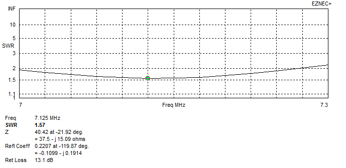
 It was not possible to get ideal SWR for both bands using only interconnecting coaxial cable. If the 40 meters SWR is not to your preference you will have to devise a more elaborate matching system. My intent was to keep it simple, and with SWR below 2:1 that works well for my purposes. On 30 meters (not shown) the SWR is 1.5 across the band.
I used EZNEC to plot the antenna current to see just how active the non-resonant element would be. The adjacent plot is for 40 meters. It is similar but opposite for 30 meters. The current on the non-resonant element is low enough to have only a modest effect on the far-field patterns.

The elevation plots show that the antennas perform as desired. They are vertical radiators with good low-angle radiation (DX) and rejection of high-angles (short path). The azimuth plots (not shown) are similarly ideal with a front-to-side ratios of -3 db, the same as for a single band delta loop fed in the described manner. Ground loss for both bands is also as expected for these heights, in the range of -5.5 to -5.8 db.
On 40 meters the gain at 10° elevation is -1.24 dbi, which is a fraction of a decibel worse than a single band delta loop with a 14 meters apex. The additional loss of -0.2 to -0.3 db is negligible. Nothing has been given up by the addition of 30 meters to the basic 40 meters delta loop.
 I made the antenna apex only about 14 meters since my intention was to have this antenna hang off my new tower with the maximum separation between it and the tri-band yagi at 15 meters height. Even at the small separation of 1 meter the bottom of the antenna would not clear the head of a very tall person. That isn't ideal but nothing more can be done without distorting the shape of the elements, which would impact both pattern and match.
The delta loops could be replaced with a different loop shape, such as the higher-gain narrow diamond loop, but not without increasing interaction with the yagi. In my preliminary modeling the sharp downward angle of the delta loop wires results in minimal coupling with a tri-band yagi only a short distance away. However this is not conclusive and would require further modelling and testing.
All for nought...
Now we move on the crushingly bad news: the antenna cannot work as intended in my station. When I reprise the model with the tower present the patterns and match are totally disrupted. It is really awful. The tower strongly couples to the antenna on both 30 and 40 meters.
Accounting for the coupling can, in principle, be accomplished but not without a lot of modelling and adjustments once the antenna is in the air. Modelling by itself is insufficient since there is great sensitivity to the specifics of the tower dimensions, grounding, and so forth. Removing resonance with tower traps is certainly possible, but complicated by the need to trap two bands rather than one.
For those of you who can mount this antenna on a non-resonant structure, such as hanging from a tall tree, this antenna may be worth consideration. I don't have this option so I will likely put up a single-band delta loop for 40 meters and adjust it to fit the environment I must deal with. It will still couple to the tower but this is a tractable problem when restricted to one band. I've done it before.
No comments:
Post a Comment
All comments are moderated, and should appear within one day of submission.