Monday, November 22, 2021

Design Choices for a 3-element 40 Meter Yagi

Regular readers will know that a 3-element 40 meter yagi is in my 2021 plan. That remains true. It is a large project that is well beyond the means of all but a small minority of hams. I am stretching my abilities to execute this project. The antenna is intimidatingly large. My tower and rotator are up to the challenge, and were chosen for this long-planned antenna, but this is new territory for me.

It is vital to get the design right, mechanically and electrically. Lifting one of these monsters is difficult and mistakes can be costly. It is daunting to consider lowering and re-raising the antenna should it not perform as expected. Consider the dilemma I faced when the stack's upper 5-element 20 meter yagi suffered a matching problem after being raised. Yet it is a far smaller antenna than this one.

Construction of the yagi and rigging for the lift are proceeding well. I am combining my own abilities with the knowledge I can glean from hams that also have one of these big antennas.

One thing I will say about hams is that they are almost always eager to help. Heaven knows that I've pestered enough of them. Professionals in the tower business also have a lot to teach, if you know one well enough to approach. I am fortunate to know such a person, and he's been generous with his time, his advice and the loan of his tools. I've learned a great deal and I am increasingly confident that I can accomplish this project.

Performance objectives

My original intent was to limit the boom to 40' or 42' (~13 meters). After modelling the antenna I reluctantly lengthened the boom to 46.5' (45.5' from director to reflector). Those few feet increased the gain a modest amount, had little effect on F/B and improved the 2:1 SWR. The optimum 200 kHz for my needs is 7.0 to 7.2 MHz. The SWR rapidly rises above 7.2 MHz. 

I decided the greater size and weight are worth it. Whether I notice the incremental performance on air is another matter.

My performance objectives for this antenna include:

  • 2:1 SWR bandwidth of at least 7.0 MHz to 7.2 MHz: improved SWR above 7.2 MHz for those occasional domestic phone contests can be achieved with a switched matching network
  • Free space gain of at least 8.0 dbi across the band
  • F/B no worse than 10 db
  • Optimized for CW and also effective on the international phone segment
  • Move the 3rd harmonic well beyond the 15 meter band, using capacitance hats, to avoid significant degradation of the pattern of the yagis comprising the 15 meter stack

I reviewed the yagi designs in the ARRL Antenna Book and rejected them. Their large 3-element design favours SWR bandwidth over gain, and there is little improvement of F/B compared to other optimized designs. 

An OWA antenna with coupled resonator has superb cross-band SWR at the mechanical cost of a fourth element, and I rejected it for that reason. A fourth element can always be added later without having to take down the antenna.

I spent several hours with an EZNEC model without capacitance hats -- for accurate SDC (stepped diameter correction) -- to explore a range of options. The important parameters are:

  • Tuning of the director and reflector (resonant frequencies)
  • Boom length
  • Position of the driven element

The design I settled on has the following parameters:

  • Boom length of 46' (45.5' from director to reflector)
  • Driven element 21' from the reflector
  • Centre frequency of 7.150 MHz, with feed point matching optimized for CW
  • Parasitic element tuning of ±5.2% from the centre frequency
Since this design is for full size elements without capacitance hats it is not an accurate representation of the antenna I am building. The measurements of the experimental dipole indicate that the reactance change with frequency with my modest size capacitance hats is only a few percent higher than with straight elements using the same taper schedule. That is, the antenna performance should be very close to the model using full size elements. 

The performance metrics were verified by careful modelling. That process is discussed in a later section. I am confident that the real world performance will closely match the manually-calibrated NEC2 proxy model, with has the capacitance hats but with SDC necessarily disabled.

Modelling challenges

Capacitance hats exclude the possibility of accurate modelling with NEC2, alone or with the enhancements in EZNEC. For example, SDC does not work. This is why we repeatedly raised an experimental dipole last year to collect real world data. The NEC2 model can, with care, be mathematically calibrated using that data. When done well the combination of modelling and measurements can a design that performs to expectations.

The parameters determined with the experimental dipole include:

  • Resonance shift with capacitance hats, including arm length and diameter
  • Resonance shift for a given length difference of the fat diameter pipes at the centre of the element and the thin diameter tubes at the tips of the elements
  • Determination of the 3rd harmonic to see where it falls relative to the 15 meter band, for elements tuned as a driven element, director and reflector

The effect of ground must be manually adjusted. The resonance and impedance of every single-element horizontal antenna is strongly affected by ground quality and height. This is done by moving the model dipole between free space and over ground of approximate characteristics. In my case the modelled free space resonance (where X = 0) is 45 to 50 kHz higher in free space than what was measured. For example, when the experimental dipole resonance was 7.300 MHz the free space resonance is around 7.345 to 7.350 MHz.

The next step was to model the dipole, exactly as built. Due to the absence of SDC and an error due to the capacitance hats the resonant frequency was calculated to be 0.938 that of reality. That is more than 6% low. The model's resonant frequency of ~6.700 MHz is the equivalent of 7.150 MHz in the ground-adjusted experimental dipole. The equivalent 40 meter operating range is 6.55 MHz to 6.85 MHz. Actually it's a little narrower due to scaling.

However, that's only true per the calibration procedure. Altering the dimensions changes the calibration. It is not usually possible to adjust the elements and then use the same scaling factor back to the real world. The adjustments should only be made to full-size elements and then scaled to the NEC2-based proxy model.

The director and reflector are scaled in a similar fashion to the driven element. Each was modelled in free space to set their resonant frequency relative to the model's centre frequency. Then it was moved to the yagi model. The complete yagi was adjusted to find the optimum design per my design objectives. Elements were isolated and adjusted, in the optimization process, and replaced in the proxy model.

Performance and relative performance

I was delighted to learn that the performance of the yagi, with its capacitance hat loads, is close to that of full size elements. This is not surprising since the loading is light to keep the elements to ~90% of full size. Shifts in the behaviour and performance become significant as loading increases

The parasitic element tuning I ultimately settled on is ±5.2% of the centre frequency. Those are the parasitic element free space resonant frequencies. Tighter spacing of the parasitic elements increases gain at the expense of SWR bandwidth, and F/B at the band edges. There is no perfect choice: do what works for you and your operating objectives. SWR bandwidth and F/B matter to me, but not as much as gain.


Per the model, and accounting for the average gain test in EZNEC, the gain of the yagi relative to the equivalent with full size elements is -0.3 db at 7.0 MHz and falls to -0.6 db at 7.3 MHz. The downward correction is included in the charted gain. It is almost certainly a result of NEC2 limitations due to the capacitance hat arms connecting at right angles partway along the dipole elements. The average gain test is a feature of EZNEC that is well worth your close attention.

The comparison azimuth plot at 7.05 MHz (below) does not include the correction for average gain. The primary trace (black) is for the equivalent yagi with full size elements. Notice the slight broadening of the azimuth pattern of the loaded yagi. This is expected for shorter than λ/2 dipole elements, and it is responsible for the gain reduction.

The F/B is a closer comparison and almost certainly immaterial. A few decibels difference at the peak is dominated by modelling accuracy, construction accuracy and real-world interactions. We'll come to the SWR curves later in the article.

From my perspective and with my stated design objectives, I am happy with the calculated performance with respect to my objectives. The slight sacrifice in gain is worth it to reduce the interaction which would degrade performance of the 15 meter yagis even more. 

Ignoring these trade-offs does not make the problems go away. They should be dealt with or at least acknowledged. Don't fool yourself.

Fine tuning the design

We are not done. Pushing NEC2 + SDC in the manner I've done has consequences. These are worth discussion since they are applicable to any yagi design, and not just big ones like this one.

The proxy model element dimensions are not the basis for the elements in the physical yagi. There is too much uncertainty in the scaling to trust the model too deeply. Instead the element were scaled from the experimental dipole measurements, as informed by the findings of the model. 

The free space parasitic element resonant frequencies are 7.515 MHz (director) and 6.800 MHz (reflector), which are the ±5.2% offsets from the 7.150 MHz centre frequency. Due to the mechanical design the dimensions of the elements that can be varied are:

  • Centre 2.375" pipe
  • ½" tube
  • ¼" tips
  • Capacitance hat arm lengths
  • Element-to-boom clamp

Since the experimental dipole survived so well for the year it was perched atop the 150' tower I do not want to risk major alterations to the yagi elements. What is easiest to change without unduly disturbing the electrical behaviour and mechanical robustness are the element centres, tips and the capacitance hats. The director is easy since it is smaller. The reflector requires more care.

The experimental dipole is now the director of the yagi because of its short 4' centre section (2' per half element) of 2.375" pipe (2" nominal, schedule 80). These lengths are extended to 5' for the driven element and 6' for the reflector. Each foot (6" per half element) lowers resonance by 100 kHz, weighs 1.8 lbs and adds 0.2 ft² of projected cylindrical surface for wind and ice loads.

There are ¼" tips on the driven element and reflector but not the director. Capacitance hat arms are 42" on the director, 43" on the driven element and 48" on the reflector. I had originally intended not to use ¼" tips since I was concerned about ice loading. Hearing about others' real world experience calmed that fear. The ⅜" section is fixed length so tip adjustment comes from telescoping the ¼" tip (if present) and the ½" tube into the next larger tube.

All the elements include ⅜" tubes, either at the tips or between the ½" tubes and ¼" tips. The rest of the elements are identical to the experimental dipole. One exception is that the overlap of the 1.9" pipe inside the 2.375" pipe is 8" rather than 12". The additional 4" per half-element lowers the resonant frequency 65 kHz.

The position of the capacitance hats along a tapered element is critical. The SDC algorithm in EZNEC replaces the tapered element with an element of the equivalent diameter. The "bumps" at tube transitions and the rate of current phase and amplitude change along the element are not accounted for. That is one reason why capacitance hats cannot be reliably modelled with NEC2 + SDC. 

The SDC algorithms works very well for elements that are not in contact and are not close to other conductors, such as for yagis with full size elements. NEC2 also has difficulty accurately modelling wires that connect at acute angles and even for right angles. You can read more about this in the EZNEC manuals at W7EL's web site.

When I extended the capacitance hat arms from 42" to 48" during last year's experiments the resonance shift at 7 MHz was 155 kHz downward. The EZNEC proxy model for these hats at the same location predicts a shift of about 130 kHz. For the adventurous this can be scaled from the SDC-incompatable proxy model (where 6.55 MHz is equivalent to 7 MHz) to 138 kHz. We still have an error of more than 10%. I therefore rely on the real world measurements, not the proxy model, to calibrate the capacitance hats for this antenna.

Dealing with the vagaries of element taper and loads in NEC2 is a very interesting subject on its own. Perhaps one day I'll write an article to give a qualitative explanation. I'll leave the quantitative explanations for those better qualified to do so. With that said I'll move on.
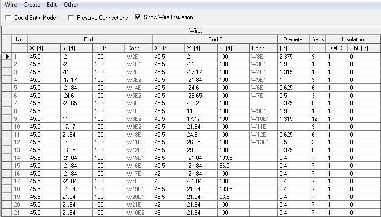
I'm showing the EZNEC wires table for the proxy yagi's director. This will give readers an idea of what the model looks like. Do not take the dimensions of the tips and hats at face value. The built yagi uses dimensions extrapolated from the experimental yagi measurements. Again, the proxy yagi model informs the design but does not dictate the design.

The element-to-boom clamps are ⅜" galvanized plate approximately 7.5" per side. The equivalent diameter with a 2.375" centre pipe is ~5.2" using the W6NL equation for a round tube on a flat plate. Since it is less than 4" of a 30' to 33' half-element the impact on resonance is small. It is less than the uncertainty in the calculations. I ignored the +10 kHz model-derived shift to the resonant frequency. Don't ignore the effect for longer plates, or in yagis for higher bands.

If all that sounds complicated enough, well, it gets worse. My documentation of the measurements of the experimental dipole were not as good as I thought. Looked at weeks and months later the scribbles jotted down atop the tower were cryptic. My blog article wasn't entirely helpful since I did not include every detail.

The most perplexing errors and ambiguities were the lengths of ½" tube at each measurement and the original length of the capacitance hat arms (42" vs. 43"). I won't bore readers with the tedious work I did to resolve all those difficulties. This is not usually a problem with full size elements since NEC2 with SDC within EZNEC is astoundingly accurate. A yagi with loaded elements is more challenging, even for the lightly loaded elements in my yagi, as I discussed earlier.

Matching

I plan to use the same gamma match from the experimental dipole. This will be supplemented with a commercial common mode choke since a coax choke for 40 meters is large, and it is a hazard with the driven element so close to the tower. 

The resonant frequency of the driven element is not critical. It is only necessary that it is of similar size to the other elements and that the raw feed point impedance of the yagi is within the range of a gamma match of reasonable dimensions. I will have to experiment with the gamma match after the antenna is raised. The element tips may require adjustment for a good match.

One nice thing about this antenna is that the driven element is within easy reach of the tower. The matching network doesn't have to be built, installed and adjusted before the antenna is raised. I can play with the gamma match and driven element at my leisure after it is on the tower.

Here are the calculated SWR curves for the 3-element yagi with full size elements (top) and that of the frequency calibrated proxy model for the real antenna (bottom):


The SWR bandwidth is better for the proxy model of the real yagi. That is suspicious. The mystery will remain a while longer until the antenna is up, the matching network built and adjusted and then measured. Although an L-network is used in the models -- since it is easy to accurately model and doesn't interfere with the SDC algorithm -- we've seen before that any of the common matching networks vary little in the SWR curves they produce.

For improved SWR above 7.2 MHz I plan to have a switchable matching network. The gamma match or a T-match must be used in combination with that network since the driven element is a continuous conductor. Due to the high rate of impedance change above 7.2 MHz a single network can likely only achieve a bandwidth of 50 kHz. That is enough for my purposes. 

As we've seen above, gain is excellent at the high end of the band despite the matching challenge. Maximum gain at the high end or above the band and best F/B towards the bottom of the band is typical of 3-element yagis. High gain correlates with a low impedance, and that is why a broadband match is impossible with one network.

Ideally the network is mounted at the feed point but that is not strictly necessary. It can be closer to the shack for convenience. The loss of LDF5-50 Heliax at 7 MHz is very low and its SWR tolerance very high at 1 kilowatt so that the high SWR above 7.2 MHz is tolerable over the long transmission line out to the tower and 150' upward. I have not yet done the calculation.

Mechanical considerations: weight, wind load, ice load

40 meter yagis are big, really big. They only look small when they're seen on top of high towers. On the ground they are intimidating. I remember helping a friend assemble a full-size 3-element 40 meter yagi over 30 years ago and, at the time, I couldn't imagine lifting it onto his 140' tower. Well, he never did follow through but I remember that antenna very well. These are antennas that demand respect.

The projected cylindrical wind area is easy to calculate so I'll skip over the details. The boom and mast plate have an area of about 12 ft². Each element is about 9 ft² (more for the reflector and less for the director) for a combined 27 ft². At the nominal maximum 135 kph (85 mph) wind in our wind zone the lateral force is 250 lb on the boom is and 550 lb on the elements. 

Depending on orientation to the wind the force will fall between those values. The standard multiplier of 2 to account for gusts, turbulence and oscillations raises the peak forces to between 500 and 1100 lb. Consider that when you listen to the weather forecast!

Ice is another matter. Element taper lessens the bending stress as you move outward from the boom. With high tensile strength aluminum alloy the antenna will survive substantial ice load, perhaps to ½" or more. If a wind storm hits when the antenna is coated with ice we may not be so lucky. Ice on the boom is not an issue since the truss provides support, however the boom must be strong in compression to withstand the horizontal force due to the higher tension on the truss cables.

I have a draft article in my files that I've sat on for a few years. In it I do a mixed qualitative and quantitative analysis of forces on a tower with a large 40 meter yagi on top. I may pull it out this winter to finish it and put it on the blog. I haven't because I am not a mechanical engineer and I don't want to make readers over-confident (or under-confident) should they choose to do something similar. I have to be careful with my approach and explanations.

All that said, I am confident that the tower, antenna, mast and rotator are up to the challenge. I know at least one other ham with the same system that has survived a very long time. I knew this from the start since I have long planned this antenna, and I chose the tower and hardware to be ready when the time arrived. That time is now.

In the next section I discuss the antenna mechanical design and not the rest of the system. Just keep in mind that the entire system has been designed with survival in mind. However, it has not been assessed by an engineer. That is why I will stop here with the discussion. Look through the blog archives to find articles about the prop pitch rotator system and the tower to discover what I am using. But don't expect to find calculations.

Mechanical design

The elements are structurally little different from the experimental dipole, and use the same pipe fitting methods. The only change is the joint between ½" and ⅜" tubes. Because the ½" tube has 0.065" walls the ⅜" tube won't telescope. Previously I reamed the larger tube enough for several inches overlap, cut a slit and used a hose clamp.

Now there are two #6 screws and a nyloc nut. A short slit ensures firm electrical contact. There is no adjustment needed or necessary since other tubes in the tips will telescope. I prefer this style for fixed joints. All the tips and capacitance hat arms have this change.

The 46' boom weighs 110'. There are two 20' lengths of 2.875" pipe joined by a 10' length of 3.5" pipe, all schedule 40. A shim reduces the gap along the 21" overlap to about 0.003" all around. The pipes are joined with 3 grade 5 ⅜" bolts each rotated 60° from its neighbours. Play is thereby minimized. This is far easier than fabricating and fitting a tighter shim.

The shim is a 2.5" × 1/16" tube that is surplus from an XM240 boom. It is split and spread to cover the pipe. Opening the tube so that it fit over the pipe was not easy for a large tube of high tensile strength. The sledgehammer in the picture (below left) played a role. The centre picture is of the element sections being joined, and the same was done for the boom sections.

I know hams who have used heftier pipes for the boom of 40 meter yagis. You should not use pipe that is smaller or of lesser tensile strength than what I used (6061-T6). The 2.875" diameter pipes were purchased used for a good price but the 3.5" pipe had to be purchased new. Aluminum is not cheap at these sizes and weights.

The boom truss is ¼" EHS and attaches to the mast approximately 6' above the boom. It is broken up with insulators since there is a 10 meter yagi directly overhead at the top of the 10' mast. Interaction is not really a problem since the truss is orthogonal to the elements. But why take chances when the cable, insulators, grips and turnbuckles are close at hand. 

The element-to-boom clamps are ⅜" galvanized plates with ½" galvanized u-bolts. These are standard parts in the tower industry. The plates and the bolts are so strong that you must be careful not to distort the aluminum pipes when tightening the bolts. The one for the driven element has 3-½" bolts for the centre boom section. I did the machining for the driven element clamp and for the boom-to-mast clamp.

The boom-to-mast clamp is 12" × 12" × ½" galvanized plate. It took over 2 hours to punch those ½" holes for the various bolts. There are 4 clamps for the boom and 4 for the mast. We don't want anything to slip, vertically or by wind torque. The centre two mast clamps are commercial tower products with a large surface area for a stronger grip. The boom-to-mast clamp is already on the tower, as you can see.

The plates do not need to be larger than what I chose. There is ample evidence of their durability in other 40 meter yagis and in commercial tower applications with even greater wind and ice loads. The heavy pipes at the centres of the boom and elements also contribute strength at those major stress points.

The boom attachments for the truss are 3/16" galvanized angle stock that cost me nothing except for time in my workshop to punch the holes.

And last, with two more elements there are 16 more capacitance hat arms, with two pairs per half element. Since they worked so well I made more of the custom clamps that I used for the experimental dipole.

Coming up: raising the antenna

A sane person would call in a large crane to lift an antenna this size onto a tower. A crane that size would be expensive and could easily run into trouble in a wet hay field. Besides, it wouldn't be as much fun as doing it without heavy equipment. So I've designed a tram system to lift this behemoth onto my 150' tower (true height is ~43 meters).

As I write this article the tram and rigging are installed and have passed their initial tests. I don't know if the antenna can be raised before CQ WW CW due to the weather and the difficulty of coordinating friends' schedules. If it does go up in the next few days it is unlikely that it can be connected in time for the contest, or made rotatable since it takes time to disassemble the rigging. That's unfortunate but it is not a job to be rushed.

This picture taken two weeks ago show the partially assembled yagi at the launch position. It's now a race against winter. Once I have succeeded (or failed) to raise the antenna I'll write it up for the blog.

Friday, November 12, 2021

Lightning Damage on a Beverage Antenna

I previously wrote that I had a lightning strike this summer and that my Beverage remote switch suffered what appeared to be lightning damage. All the relays connected to Beverages blew their integrated suppressor diodes. The damage went unnoticed for several days since I rarely venture onto the low bands during the summer. 

At the time I was just happy that all the equipment and antennas seemed to be okay. Of course I was eventually going to find out what had really happened. It took a few weeks for me to notice.

The season has progressed to the point that it is possible to navigate the summer growth in the Beverage field. I found where the lightning struck and the full extent of the damage. 

It was a direct strike and not a secondary one as I originally thought. Lightning is funny: there are two very high towers nearby yet the strike hits an antenna that is 2.5 meters off the ground. There are many things commonly misunderstood about lightning which I will not delve into in this article. Lightning can and does frequently plague Beverage antennas (scroll down to "Why composition types?").

Discovering and resolving the faults involved several steps. The first was to repair the switch. The relays were replaced with identical devices from my stock. I always order more than needed so that I can repair the devices I build. It is inexpensive insurance. 

I ought to use relays without integrated suppressor diodes so that I can use 1N4007 or similar devices with a high voltage rating. It was faster and easier to dig into my stock and I am busy this fall. Next year I will reconsider the design of the switch and, as a minimum step, replace questionable components with better ones.

After testing the relays in the Beverage switch I installed it in the field. There was some risk since the Beverages themselves had not yet been inspected for lightning damage. Each antenna head end uses two SPDT reed relays for reversing directions with the DC power supplied by the switch on the RG6 feed lines. Those reed relays use external suppressor diodes of know type. I am more confidence of their robustness. If a voltage surge is brief enough it is possible for semiconductors to survive.

To my delight the switching electronics of all 3 Beverage antennas worked. That means the relays and suppressor diodes survived. Diodes that fail in this fashion usually short, which is easily noticed when reversing current is supplied. The celebration was short because, unfortunately, the blown relays were not the only problem.

The north-south RG6 reversible Beverage worked, but the others did not. From the head end side at the edge of the bush all I could discern was that one wire of the 2-wire NE-SW Beverage was a little slack. That's where I left matters until a friend dropped by to help and we trod our way into the bush. 

We discovered wire breaks in two places: one on the NE-SW Beverage and one on the E-W Beverage. The causes of the failures were quite different.

The ground wire on the E-W Beverage reflection transformer was chewed through. This is the same problem I've dealt with several times on the 80 meter array. The reflection transformer at the eastern termination of the Beverage is at the edge of the swamp (I own part of the swamp) and the local hunters know this as a good place to stalk deer. The wildlife keeps to this narrow strip of bush between the open fields and the swamp. It is also coyote country since they hunt the deer.

The shredded AWG 18 stranded wire was replaced with AWG 14 stranded wire. This time I used a slightly longer length so that it could sit close to tree and rotting log below over the path to the ground rod. In my experience, deer are more attracted to wire dangling in midair.

After this simple repair the E-W Beverage worked. Although it wasn't lightning damage the break and the repair were part of the process. Now we come to the NE-SW Beverage and what the lightning strike did to it.

The reason for the slack wire was easily found. About 100 meters along the 175 meter long antenna the wire was cut. On closer examination we saw that the aluminum wire was vapourized. It was thin as aluminum foil at the tips. Probably there was a hot spot where the current flowed and the wire melted and tore apart.

By pulling the broken ends together we determined that only a short length of wire was gone. The ends met at a dead tree (pictured at top of this article). The tree supports the Beverage wires using screw-in electric fence insulators. The now empty insulator had a carbon track on it that led to the tree trunk. It would seem that the dead tree is now a little deader. 

We could not determine whether the lightning first struck the wire or the tree. Because the tree was dead it was not easy to tell what damage, if any, was caused by lightning.

One nice thing about aluminum wire is that it is easy to splice. Aluminum oxide that coats aluminum soon after exposure to the atmosphere is conductive. Aluminum electric fence wire has the tensile strength to withstand tension for fences and Beverages, and it is stiff enough to hold together when two wires are twisted together. 

I used a longer than necessary length of wire to splice the ends together since the original wire may have lost its temper surrounding the break. Until the wire tension was restored I couldn't be certain how much of it had been lost from the flash heating.

The dead tree is not doing well. I will likely have to replace it with an artificial support for the wires in the next year or two. Unless lightning strikes the same spot twice it'll last that long.

I set the tension at the northeast end and returned to the southwest termination where the head end electronics are located. There I discovered a curious problem. The galvanized nails I use for an improvised rope cleat had been consumed by the tree. The growing bark rode up the nails and half covered the ropes.

The nails could not be easily removed so new nails were hammered in. It took some pulling to pry the rope out of the bark on the old cleat.

When I tested the Beverage after sunset I discovered that this time I was not so lucky with the repair. The Beverage worked after a fashion: the reversing relays worked, but the directivity was poor.

Summer growth had to be cleared along the 175 meter length of the wire, and there was a lot of it! It had to be done anyway and there was a chance that the work would restore the antenna. It took three hours for two of us to cut and prune tree limbs. Bare Beverage wires touching trees limbs are not often a problem since the impedance is high and the contact points with foliage are not very conductive.

With the physical damage dealt with and the problem unresolved it was time to troubleshoot the electronics and transformers. These include the head end and the far end reflection transformer. Opening the enclosures showed nothing amiss other than insect litter. 

I disconnected both enclosures and the ground wires and took them indoors for further testing. Before proceeding I cleaned them of the insect litter. A spider living alongside the reflection transformer was evicted. I plugged the weep holes of both boxes since they seem to cause more problems than they prevent.

Testing is no different from what I did while building them. The only difficulty was that to individually test components they must be de-soldered. I didn't bother with that. 

Ohmmeter and through-the-box impedance tests strongly indicated that they were working as they should. 

The impedance transformations were as expected, the relays switched and the physical Beverage wires were repaired, yet the Beverage had poor directivity. The next suspect was grounding.

Inspection of the grounds bore fruit. Below is the ground wire lug that connects to the head end stud. It is badly corroded on both sides and rust stains coated the stainless washers. I must have made a mistake when I selected the lug from my stock since I believed it was tinned.

I replaced the ground wires on both ends of the Beverage with tinned insulated wire. For a simple and reliable connection I tinned the stud ends of the wires to make them rigid and formed them into a J for wrapping around the stud. I no longer trust my stock of studs. Short copper strips of copper were soldered to the other ends for a copper-to-copper electrical connection to the copper-plated ground rods. I now have this style of ground rod connection to all the Beverage grounds.

I chose pink wire as an experiment. All the wires the deer chewed are black. Perhaps a brighter colour will be less attractive to them. The experiment is cheap, so why not.

Epilogue

Re-installation of the Beverage boxes was completed a little before sunset. A few hours later I was relieved that the antenna was working. The full Beverage system is now back online.

It is interesting how much of the damage had nothing to do with lightning. Nature doesn't rest during the summer months when the majority of hams abandon top band. The faults that were not caused by lightning would have been discovered anyway and the repairs made regardless of whether there hadn't been a lightning strike.

Beverage antennas are simple to build and maintain since they are so low. That low height makes them susceptible to frequent animal and vegetation damage. Their length makes them susceptible to lightning induced surges.

Repairs are usually easy but their regularity is annoying. Vertical arrays are easier to maintain and typically perform better, but they are complex and are beyond the ability of most hams to design and build. Commercial products are expensive. I'll stick with Beverages for now.

It is deer hunting season. Considering how much damage deer have done to my antennas this is welcome. I say that despite my love of wildlife. They can be pests and a danger, and they draw coyotes that extend their gaze to the local farmers' livestock. I mention this because I raced to complete the repairs before hunters arrive on my property. They requested access and I happily agreed. They're responsible people but I prefer not to be in the bush when they're present.

Lightning is funny (weird)

To repeat what I said at the start of this tale: "lightning is funny." It doesn't particularly care for tall conductive structures and it jumps on and off metal conductors seemingly at random. It may seem strange that it would vapourize a wire, draw an arc from a rotary switch 250 meters away, blow a string of relay suppressor diodes and leave everything else undamaged.

What did survive? Transceivers, relay coils and contacts, electronics, tiny transformers wound with thin enamel coated wire and so much more. I can't say whether the multitude of ground rods in the Beverage system, buried coax and control cables, and more robust ground rods at the towers and house entrance did any good or were merely bystanders during the event.

Coincident thunder and lightning are never a good sign. Check everything, no matter how good your grounding system and protective devices and procedures. Lightning has a mind of its own. It can devastate the best protected station and leave an unprotected station unhurt. Don't gamble. Employ the best lightning protection system you can afford and you are far more likely to survive the inevitable.

Friday, November 5, 2021

CQ WW SSB -- SO(A)SB15 HP

My station is a mess, inside and out. Regular readers will know that CQ WW SSB occurred in the middle of my fall antenna and tower work. Some antennas work, some don't; some turn, others don't. An all-band entry would have had to be only for fun since I could not possibly be competitive.

By narrowing my focus I was able to have a fun contest experience. Many contesters do this when a major effort would be daunting for any number of reasons. You don't have to do the same thing every time. Years ago when I spent a few years as a QRP contester with a small station it was possible to go all band and have a pleasant time since. To be blunt, it was difficult to be heard on the low bands and where the QRM was fierce so I could keep regular hours and not be sleep deprived. QRP contesting was enjoyable and educational but it was time to move on.

My present station with its tall towers and big antennas entices me to reach for the top. Well, I'm not quite that ambitious but having some muscle on the bands can be a lot of fun, though of a different type than the fun of QRP.

I looked at the state of my station, my objectives and the propagation forecast and entered the SO(A)SB15 HP category: Single Op, Assisted, Single Band 15 meters and High Power. This is a valid category in CQ WW, unlike in the ARRL DX contests for which I invented my own similar category earlier this year. I chose assistance (cluster spots) to see how high I could drive zone and country multipliers with my big signal.

I ran when I could and jumped on multipliers as they appeared. At intervals I would spin the VFO to see what I could dig up that wasn't yet spotted. The pace was less than frantic outside the morning hours of the European openings. Overall it was pretty relaxing. I ate at near regular times and I was able to take many short breaks. The only schedule pressure was waking up before dawn to be ready when 15 meters opened.

Antennas

I have 3 antennas to choose from for 15 meters. These are the two 5-element yagis comprising the stack and a TH6. Either or both of the yagis in the stack can be selected. The lower yagi is fixed to Europe. The side mounted TH6 is not currently rotatable because I have not completed the wiring all the way back to the shack. It's a straight forward job that is delayed while I do higher priority tasks in the rush before winter weather arrives.

The antenna controller I am building is not done. The project has not progressed over the summer due to other priorities. For the interim I wired up a simple controller using ON-OFF-ON switches mounted on a peanut butter jar lid to operate the stack switches: upper, BIP, lower. 

There is also a companion switch for the 20 meter stack and a hole that is waiting for the 10 meter stack wiring to be completed. Somehow I crossed wires for the 15 and 20 meter stack switches that caused confusion until the problem was identified. I temporarily swapped wires on the basement patch panel since that was faster and easier than resoldering wires.

There are several ways the stack can be employed during a contest:

  • BIP towards Europe. That's my only direction with full stack gain until I put a rotator on the lower side mount yagi.
  • Use the lower yagi for Europe and hunt multipliers with the upper yagi.
  • "Spray" in two directions at once while running, with half the transmitter power going to each (-3 db). When a station is difficult to copy you increase directivity by selecting the yagi that favours their direction.
  • Alternate CQs between each yagi, which are pointed in different directions.

I used all of these techniques during CQ WW. The stack worked especially well to Europe and the upper yagi did wonders for the long DX paths: SA, Asia, Africa, etc. Aside from geographical propagation differences the stack antennas were very competitive with other North American big guns.

One inconvenience was the lack of a direction indicator. I have a design and I have the parts collected in a jar on my workbench. Until it's built all I can do is count time (I roughly know the rotation speed of the prop pitch motor), peak the signal by ear or run across the house to look at it through a window.

Numerous times the accuracy of the heading was quite important. The beam width of a long boom 5-element yagi is sharper than what most of us are accustomed to using. With a 3-element yagi you don't need to get the direction too accurate to have close to maximum gain where you want it. In many pile ups or needed multipliers with a weak signal close isn't good enough.

The comparison plot the show how the 3-element yagi can outperform a 5-element yagi when the station is off the beam centre. I found that the difference is more profound compared to the TH6, probably because the upper 5-element yagi is twice as high. 

In several cases I repeatedly called stations 30° to 40° off the direction of the 5-element yagi without success. Turning it 10° to 20° degrees closer the signal strength rise is astounding. With that adjustment it takes just one call to put them in the log and I'm on to the next multiplier. It can be more time efficient to turn the yagi to the station and back again afterward.

The TH6 was a disappointment. It developed an intermittency when wet and it rained quite a lot during the weekend. Like most tri-banders the bandwidth is narrow and the antenna is optimized for CW. Running full power high in the 15 meter band tripped the SWR protection of the amplifier. When I needed the antenna I reduced drive and hoped for the best.

The TH6 will perform far better in CW contests when I finally wire up the rotator. Or so I hope.

Propagation

Cycle 25 is on the rise and so are the prospects for propagation on the higher HF bands. With the solar flux crossing 100 the 15 meter band is once again full of life. I was not deterred by the prediction of a CME-induced geomagnetic storm. A storm would not wipe out the band and everyone would be affected by poor conditions. That said, a storm would affect me more than many others due to my high geomagnetic latitude. Sometimes I do abandon a contest when conditions are especially bad.

As a Canadian I'm used to that since many of our DX paths are polar and we're already penalized on the high bands by the shorter fall and winters days in comparison to points further south. I am just thankful that I am no longer a VE4 since that is a far more challenging location from which to do DX contests.

The terminator plot comes from N1MM Logger+ and shows what the world looks like from here shortly after sunrise when the 15 meter band opens. It does open before sunrise but those are forward scatter signals of low intensity that are difficult to work. There is little point in trying since they'll be very strong an hour later. For me that time was around 8 AM (1200Z).

The sun is setting in west Asia when it is rising here. There were a few very weak Russian signals from zone 18 that I failed to work. The same was true of Indian stations in zone 22. However there were several strong stations in central Asia that delivered valuable multipliers. It is a more reliable path. When the band closed for us to those distant zones my attention focussed on Europe and European Russia. 

The bulk of the European opening ended around 1600Z. They still had conditions to the US on the more southerly paths, but not so for me over the northerly path. That limited my ability to "bulk up" on DX for QSO points. Outside of those 4 or 5 hours the rate slowed considerably. Working lower point value Americans was limited by the long skip that hopped right over all the major population centres of the eastern US. We need a higher solar flux to effectively work the US on 15 meters.

A mirror image of the same propagation occurred in the early evening at our sunset when the sun was rising in Japan and east Asia. Stations a few hundred kilometers to the west and south had far more success, with the big guns able to run Japanese stations. That was not possible here. All I could do was eke out every multiplier I could before signals faded for good. There were very patient operators in China, Phillipines and elsewhere who stayed with me under weak signal conditions to make those valuable QSOs.

From noon to late afternoon the QSO rate is low. It is a mix of Caribbean, Central and South America and a steady but slow number of US stations. A few Africans in badly needed zones and countries make up the rest. The contester population south of the equator is low and they attract a lot of attention from contesters in the north. 

The sum of the effort chasing multipliers is very positive to the score even if it is slow going. Marginal propagation and pile ups on popular DX stations were an excellent test for my new antennas. Propagation was not great this weekend but well suited to my objectives.

DXpeditions

Zone and country multipliers are key to a high score in CQ WW and similar DX contests. The small number of DXpeditions in 2020 due to the pandemic reduced the multiplier potential for all entrants. Rankings were little effected since everyone had to deal with it. For 2021 many of them are back. This increased interest from both contesters and casual operators alike. Contests are a great way to chase DX.

The good conditions and presence of DXpeditions were the spurs that prompted me to do this single band effort in the assisted class. Being assisted allowed me to pursue multipliers with a vengeance and to test my station against other big guns in the pile ups and (importantly) hear weak DX stations over particularly difficult and marginal paths. Many of them have small stations that are difficult to hear.

The chase was a lot of fun, I did well and I learned a lot about the capabilities of my station. DXpeditions are a great way to spice up the bands and renewed contest travel takes it to a higher level. Everyone on both sides of the DX QSOs seemed to be enjoying themselves.

Running

The bigger the signal the higher the number of QSOs and multipliers. Since QSO points and multipliers, well, multiply, the increase in score can be dramatic. The percentage of contacts from running will also be higher since there is a limit to how many contacts you can make by S & P (search and pounce). It is a matter of searching, checking the log then calling, and sometimes having to wait and try again.

With practice you can improve S & P success, but there is a limit no matter your skill. For example, you will never work stations who, like you, only S & P. It is therefore no surprise that most of my contacts in the contest came from running. By calling CQ you can everyone except the small fraction of stations who can run forever. These are mostly those in countries that are rare multipliers.

Many contesters love running. They love it so much that they travel to DX locations for the major contests. As a highly valued multiplier they can run the entire contest. If winning is the objective they must not run all the time. S & P is still necessary to work many rare multipliers and some of the big guns in more populous countries who mostly run as well.

I've written before that I don't particularly enjoy running, or at least not to excess. Nevertheless that is what I did contest weekend during the 4 to 5 hour long European openings in the mornings, from soon after sunrise until midday. I'm a big gun now with my 5-over-5 stack and a kilowatt. Running Europe was responsible for most of the contacts in my CQ WW log.

SSB is wide bandwidth compared to other modes and phone requires no special skills to operate: click the PTT and talk. The result is heavy QRM and many calling at the same time when the path across the Atlantic is in good shape, as it was for the contest. Running below 21.1 MHz helped since it cut the QRM from US stations, and from the far stronger Europeans calling US runners.

Your job is to pick calls or partial calls out of the bedlam and hope that only that one station replies. Many stations keep calling regardless because they want to make QSO quickly as well and move on to the next station. Speed and efficiency are good for you and your callers. Stumble too much or take too long to work through the callers and they'll leave. Maybe they'll come back later, or maybe not.

Pulling weak phone signals out of the QRM of overlapping and splattering signals is a skill that takes time to develop. Few casual operators bother, and even if they could they may not be able to make their CQs heard. I'm reasonably good at it since I've done it so much. Having to do it for hours on end is a grind. This is one of the reasons why I prefer multi-ops for phone contests: to be able to take breaks from the craziness.

One of the nice things about running with a big signal in a DX contest is who answers. Many stations in rare countries call me. Indeed, running is one of the "secret" weapons big guns have. Most hams, and that includes hams in interesting places, are casual operators who avoid running because of the pile ups that ensue. For them, ham radio is recreation and not competitive. They scan the bands and call whoever interests them. When you don't run you will miss those multipliers. With the station I now have I must run to be competitive.

Headset woes revisited

The Koss SB45 headset I recently purchased did as well as I expected. The quality of received and transmitted audio was good but my head ached after several hours. It was my best option at the time and I knew what I was getting into. 

The headband can be stretched a little. I did that before the contest, and again during the contest, to reduce the pressure against my head. I survived the contest without excess discomfort. Finding ideal headsets is not easy.

Another problem presented itself when I turned the big yagi north to work east Asia. This is the direction that points the antenna directly towards the house and shack. There was distortion of the mic audio heard using the rig's monitor function. No one complained about my audio (in fact, I got numerous positive reports of my audio quality) so I could not easily determine whether the RFI affected the transmitted signal as well.

After several minutes of worry I reached into a desk drawer and pulled out a snap-op ferrite core. I wrapped the cord (leads for both mic and headphones) around the ferrite several times and snapped it shut. 

The distortion in the monitored audio disappeared. I can only wish that all my station difficulties are so easy to solve.

While not directly related to headsets I have work to do on my stored voice messages (CQ, exchange, etc.). Canned messages greatly reduce wear on our voices, facilitate SO2R operation and permit more attention paid on other matters such as new cluster spots and checking propagation indicators. It is important to match the mic and message levels, and that the voice and voice cadence be as similar as possible. I have a tendency to record bland sounding messages and speak with intensity. I'll have to record better messages.

Results and lessons learned

When it was all over I logged over 1800 contacts in 34 zones and 137 countries. I am pleased with my multiplier total since it is competitive for this region and demonstrates that my antennas are working well. Further south the big guns did better. I will have to wait for a higher solar flux to open up the polar paths so that I can work more multipliers and run stations in Japan, and shorten skip so that I can work more Americans.

It is not enough to put up big towers and antennas to do well in a contest. You not only have to know how to use them to best effect, you must also be skilled at running, SO2R, hunting stations and have a keen eye on DX openings that can be marginal at best with small antennas at a lower height. I have much to learn and relearn.

I was also able to reaffirm that sitting in the chair for long periods in a phone contest is not really what I want to do. Once the station is better organized I will be inviting friends to do these contests as multi-ops.

Coming up: CQ WW CW and other major contests

The only change for 15 meters in advance of the CW weekend of CQ WW in late November is to fix the TH6 and finish wiring the rotator. Of more importance are the 3-element 40 meter yagi and the Beverage receive antennas. The direction indicator for the upper 15 meter yagi is lower priority.

The former project is progressing and there is a good chance it'll be built and raised in time. The Beverage system was struck by lightning this summer. It was a direct strike rather than a secondary strike or voltage induction as I first suspected. More on both of these in future articles.

The upper 10 meter yagi is connected and working, and that will be good to have now that the solar flux is rising. It is unlikely that the lower yagi will be connected this month, and that means no stack. If the weather cooperates I would like to get the full stack cabling and switching done in December.

I will operate ARRL Sweepstakes but not a full time effort for either CW or SSB. I have too much to do and the contest doesn't interest me as much as in years past. In any case the stacks are optimized for DX contests with the lower yagis on 10, 15 and 20 meters fixed towards Europe. 

What I'd really like is to have my first multi-op for one or both of the ARRL DX contests. It can be a lot of fun and I am spared the 48 hour marathon of a single op and the intense activity to be expected with my much bigger station. There is a lot of work yet to be done to be ready to do that.

Friday, October 29, 2021

Lifting the 10 Meter Yagis

Lifting the newly built 10 meter yagis onto the tower was done by tram line in a fashion no different than I've done before. However, I feel that it is worthwhile to review how it was done and to mention a few noteworthy points about the lift and antenna behaviour. A full assessment of their performance will have to wait until I gain more experience with them which, as you'll see, is not yet possible. 

Both of the 10 meter yagis were tuned using the same rope tram line used to lift the TH6 to its new rotatable side mount at around the 75' level of the 150' tower. The tram line and haul rope were then raised 40' and used to lift the lower yagi to its perch at 110' (on left). The side mounted lower yagi is fixed to Europe. 

The lift of the lower yagi was done without helpers. It was not difficult to achieve good balance and orientation for a small yagi and it is light enough to be raised by one fit individual. The lift was incident free so up I went and bolted it to the side mount bracket. That was the easy one of the pair.

To lower the antennas that were up top and to raise the upper yagi a steel tram line was anchored to a large and healthy tree in the bush at the opposite end of the hay field. I previously mentioned clearing a path to the chosen tree. Although not needed for raising this yagi, or for the preceding lowering of the TH7 and 40 meter dipole, using the tree was a trial run of the basic setup that I plan to use for raising the 3 element 40 meter yagi that is currently under construction. That's a big healthy tree, and a hefty chain to match.

As I briefly mentioned in a previous article, the TH7 and 40 meter dipole at the top of the tower were taken down earlier in October. Several friends came over to help on the ground and, as usual, I did the work on the tower. Only one friend (VE3KAE) was needed to raise the upper 10 meter yagi on the same tram line. For these higher jobs I prefer a helper even though in this case the upper 10 meter yagi is lighter than the lower yagi that I lifted on my own.

Notice the rope around the big tree? It is a safety line from the tree to the tram line cable termination. Winches are mechanical devices that can fail due to excess use and defects. Nothing is forever. When the tram line is at the desired tension, the rope is pulled tight and serves as a backup in case a problem arises. It does happen, as I can assure you from personal experience. No injury resulted in that incident (people or antennas) but it easily could have. Use a safety line.

Just because I like it, I included a shot of the upper yagi from the top of the 150' tower when it was less than 100' feet away (the tram line is 350' long, or 110 meters). Later I describe how I handled it when it arrived. The rigging for the tram ride is not always ideal for an easy connection to the mast.

The bracket for the lower yagi previously supported the TH6 that is now on a rotatable side mount further down the tower. I took the opportunity to improve the bracket and replace clamps that were showing their age. Although there are 5 elements squeezed onto a 24' boom, the wide director spacing of the optimized design allows the 10 meter yagi to comfortably fit on the bracket in any orientation without any element getting overly close to the tower.

There are nevertheless interactions, as I fully expected. For example, the SWR is not what it was when tuned. There are guys off the rear sides and one in front, towards Europe. Per my guy wire interaction model the interaction is likely to be primarily with the rear guys. I have not yet confirmed this in a model.

Although the guys are not terribly close (the picture is deceiving) and largely orthogonal to the antenna elements it takes little to disturb the pattern of a 10 meter antenna. The segments of the broken up guys are non-resonant on 10 meters but are large enough to couple regardless. I had a similar effect with the side mount 15 meter yagi but not the side mount 20 meter yagi. Size matters. I expect the antenna to perform well regardless since the impedance excursion is small and I know from other hams with similar installations and my own experience that gain remains very good.

I am unconcerned about a few minor lobes in the pattern since my interest is contests and a little radiation in various directions can pay dividends, and modest interactions don't reduce the forward gain by much. The minor lobes attract more callers without allowing too much QRM. Others with different operating interests might be more concerned. The only practical way to achieve a perfect pattern for side mounted 10 meter yagis (and for 6 meters and other VHF bands) is to use non-conductive guys.

Unlike the upper 10 meter yagi the SWR on the lower yagi is not what it was after the gamma match was adjusted at a lower height. I don't yet know how much of the change is due to tower and guy interactions and how much is due to me. The human body couples poorly but noticably on 10 meters. Antenna behaviour is affected by the proximity of my body (notice the reflection in the left panel).

The effect is reduced by standing vertically below the boom and by standing farther away. The good SWR of the upper yagi was not so good when I measured it the same way as I measured the lower yagi. The coax from the boom to the analyzer was only 2 meters long. The SWR on the right was measured when the antenna was at the top of the mast and I was at the bottom of the mast.

Now let's turn back to the raising of the upper yagi. Alan VE3KAE took a picture of me (on the left) as I took possession of the yagi at the top of the tram line. With the tram line slackened we lowered the antenna until the boom-to-mast clamp rested on the top plate of the tower. This was necessary so that I could move the chains and shackles for the tram pulley and haul rope onto the far side of the clamp plate.

The geometry of this rigging doesn't always make it easy to do the whole job with the same rigging. The large plate and integrated boom truss support made the transition mandatory. I was able to get one saddle clamp attached in this awkward orientation so there was no risk of an accident while I did the rigging. To save time I tossed no longer required chains and attachments to the ground. 

Always make sure to get your ground crew out of the way when you do this and only if you can comfortably send the material clear of guys and the antennas below. Stuff like this easily survives the 150' fall and it saves me the time and effort of carrying the rigging down with me. The steel strikes the ground fast enough that it is partially buried. On this climb I somehow knocked loose the little radio I used to talk to the ground crew and down it went. Unbelievably it survived the fall and still works!

With the antenna firmly clamped to the mast I rotated the boom so the elements were perfectly horizontal. I then adjusted the truss turnbuckles to level the boom. The turnbuckles are out of reach when the antenna is raised to the top of the mast. The next step was to remove the anchor plate (for the tram line and haul line pulley) from the mast, step the mast and hook a pulley to the top of the mast. The haul rope is threaded through this pulley down to the antenna.

It's a tedious process because I must then remove the steps to slide the antenna up the mast. Everything must be done with safety foremost, and that what takes the time. The procedure of the lift itself isn't difficult. I am deliberately avoiding details of mast stepping and mast climbing so that I don't give any ideas to overly enthusiastic readers. This is not a job for the tower novice.

With the rope pulled tight I loosen the mast clamps. While my friend pulls the rope I push the antenna upward. I again step the mast and follow it to the top. It's faster to remove the clamps and let the antenna climb freely, but it is not so easy to do the fine mechanical work of inserting the clamps (and not dropping hardware!) while perched at the top of the mast. So I do it the slower way.

To get the antenna to the very top requires rigging the haul rope to the bottom of the antenna. Otherwise you can't lift to the very top of the mast. Even so the rope jammed within inches of the top so we called it a day and I tightened the clamps, removed the rigging and climbed down.

I dress the cables accounting for the arbitrary direction the antenna ended up pointing. My home brew prop pitch motor controller allows infinite adjustment, and the direction pot on the tower has a 10:1 drive ratio, so that also allows essentially infinite adjustment. Calibration in the shack took 5 seconds.

The antenna works and it is ready for action. The lower side mount yagi will be without a coax connection until I build a 10 meter stack switch. It will make a triplet with the L-network 20 meter and 15 meter stack switches I built.

I'll close with a pretty picture. We are looking along the boom of the upper yagi towards Japan. The solar flux is high enough to work Japan on 15 meters and it won't be long before they are booming in on 10 meters. It is no accident that the 10 meter yagi project occurred this year: the solar cycle allowed me to delay until now, but no longer. 2022 is going to be a very good year for HF propagation.

Sunday, October 24, 2021

Headset Woes

I operate SSB from time to time even though it is not my favourite mode. My usual forays to phone are contests and DXpeditions. I periodically use my big signal to run DX stations on phone, for fun and a change of pace. Microphones are otherwise pushed aside or unplugged to tidy the operating desk.

There are several styles of microphone with which we are all familiar:

  • Handheld
  • Desktop
  • Boom
  • Headset

Handhelds are fine for the occasional use at the operating desk, but are more appropriate for mobile operators. Having to hold a PTT button is tiresome for long operating sessions and contribute to transmitted noise due to hand pressure and movement. For my style of operating a hand mic is purely for emergencies when my preferred mic fails. Most rigs include one so I have quite the collection.

Many HF operators love desktop mics. Quality is often excellent and they are suitable for both PTT and VOX. I don't like them because you have to hold your head still, as if it was in a virtual vice. That makes it difficult to fiddle with the computer and rig while talking and it is uncomfortable for long transmissions and operating sessions. It blocks keyboard access, takes up valuable desk space and blocks my view of the rig.

Boom mics share many of the characteristics of desktop mics but allow your head to remain upright because they can be positioned more conveniently. Decades ago, my friends and I used to tape small mics on swivel stands repurposed from desk lamps for contest operating. PTT is a foot switch or VOX. I gave up on them after my first experience with a headset.

Headsets are worn on the head and include headphones and a microphone in a single unit. Like many contesters, this is what I prefer. Headsets have significant advantages:

  • Do not impair vision and access to the keyboard and equipment
  • Consistent audio level and quality since no matter how your head or body moves the mic is always in the same position relative to the mouth

It is no surprise that there are a variety of headset options that are of interest or concern to hams:

  • Comfort when worn for long periods (typical for contesters and DXpeditioners)
  • 3.5 mm or USB connectors
  • Wired or wireless
  • Electret or dynamic mic element
  • Flat or voice communication audio response
  • Enclosed or open ear enclosures for the headphones
  • Servicability
  • Quality: longevity; resistance to abuse; reliability

Once the domain of hams and professional communicators, headsets are now used for e-games, video and voice internet communications, and call centres. Supply serves the demand, so the market offers an abundance of choices for those applications. 

Unfortunately the quality is often poor and price is an unreliable indicator of quality. Since most products are targets at internet and computer use, those of good quality may score low on our requirements. Products specifically made for hams and other communicators also have deficiencies. There are more choices than ever but few that are great.

Let's look more deeply at several of the options that are pertinent to HF operating.

Comfort

Let's face it, most headphones and headsets are uncomfortable after several hours. For a contester that's a problem. When my head and ears are throbbing in discomfort, and sometimes pain, it is difficult to continue. There are very expensive headsets that are uncomfortable and there are cheap ones that are comfortable. Sometimes it helps to take my glasses off since it reduces a critical pressure point and my vision is adequate to operate the computer and radios.

One of the most comfortable and reasonably priced headsets with full ear enclosures is the Yamaha CM500 (pictured above). Many contesters agree. Unfortunately it has been discontinued and there is a dwindling supply. Although it is reputed to be robust that is relative. The mic on mine quit and it is pretty well impossible to service.

Many similar looking headsets are not as comfortable. The headband of some, but not all headsets can be spread to lessen the pressure. 

If the plastics used for the band or the ear enclosures are stiff or thin there is very little that can be done to make them comfortable. The comfortable plastic covers on many headsets wear out quickly because they are soft and pliable. This happened to my Koss SB45 headset, along with a broken wire in the cord (see picture at right).

Don't expect to be allowed to try on a pair in a store. Your best bet may be to ask your friends with similar operating habits for recommendations. Only ask those with fewer opinions and more operating experience.

Personally, I have always favoured open air headsets and headphones that sit on the ear without an enclosure. My ancient Heil headset is like that, and if the cord hadn't failed I might have continued using it. Most hams need ear enclosures to eliminate household noise, but if you can close the door of the shack that may be good enough unless you have amplifiers with big fan noise.

Connectors

You will find that many headsets have a USB cable for direct connection to a computer. You can use these if your logging software or other application can route the audio to the rig mic and headphone connectors via the sound card ports. Contesters often do this since it simplifies station cabling, mutes the mic while playing voice messages, recording messages on the fly and support audio routing for SO2R. For example, the N1MM contest logging application. That may be difficult to do outside of contests and without specialized software.

There are adapters available to convert USB to 3.5 mm stereo for both headphone and mic audio. Otherwise you may prefer to choose headset with 3.5 mm plugs. Many older radios, and a few new ones, have unique mic connectors for which you'll need adapters.

The choice will depend on your station and your operating preferences. Be very careful to read the fine print before ordering or you'll waste your money.

Wireless

Headset cords are a common failure point, and they often get in the way. It is inconvenient to be "tethered". Only some of the most expensive headsets allow cord replacement. You can try to replace or repair cords on other products if you have endless patience and you are prepared to employ destructive measures to pry them open, and try to reseal them afterwards.

Wireless headsets would seem to be desirable since there is no cord. The problem is that battery life is measured in hours, and that is insufficient for operating a contest. For some, the battery pack goes has to be placed in a shirt pocket. The other end of the wireless link is typically only for connection to a computer, and that may not work for you.

Mic element

The vast majority of headsets have a flat response. For "talk power" hams prefer a strong mid-range peak that accentuates communications at the expense of fidelity. Long ago the only good option was to select a mic element designed to do this. I had one of those elements for my first Heil headset. Special elements are no longer necessary since most high end rigs include a programmable equalizer. 

When combined with a speech processor the improvement in average power, and therefore being copied by others, can be quite impressive. There is no need to over-amplify or over-process the audio. If you do expect excess distortion and splatter.

What you never want to do is use one of those voice accentuating mic elements and an equalizer that does the same. Use one or the other. I prefer a flat electret mic for my headsets. Swapping headsets has no effect on audio processing and you have a far greater choice of commercial headsets. Leave the equalization to the rig.

You also need to consider the type of mic element. There are really only two that are of interest to us: dynamic and electret. There are still transceivers that only support dynamic mics, yet the majority of mics have an electret element. There are a few modern transceivers that have insufficient gain for the lower output dynamic mic, and for those you must use an electret element. 

Apart from gain, an important difference is that the electret mic requires DC power. Pretty well every computer sound card has this feature, as do many modern transceivers. For rigs that don't you'll need to buy or build an adapter that AC couples the audio and supplies DC bias to the element. The Yamaha CM500 includes a battery-operated adapter. I customized an adapter than connect a 3.5 mm stereo plug to the 8-pin front panel jack of Yaesu rigs, and taps the DC pin to bias an electret element and a capacitor to block the DC from the audio signal path.

Reliability and servicability

Perhaps the least reliable part of a headset is the cord. Every movement of your head makes it shake and it bends when you take them off, so that over time the thin wire fatigues. Thicker insulation and strain relievers help but do not cure the problem. Very few headsets allow cord replacement, or of any other part for that matter. Not even the plastic ear pads can be replaced when they inevitably wear out.

I have found that the cheaper headsets are not up to heavy use day after day. The cord becomes intermittent, the mic element fails or the plastic tears or crumbles. They are sealed units that cannot be opened without damaging them to a lesser or greater extent. There are expensive headsets that are easy to repair and replacement parts can be ordered. Unless you really like those headsets it is poor economy since several cheaper and often more comfortable headsets can be purchased for the same price.

I have looked around and canvassed fellow contesters and my reluctant conclusion is that headsets have a limited lifetime. They are perishable items, like batteries. When they fail, you discard them and buy another headset. There just doesn't appear to be a sensible alternative. There are contesters who have stockpiled several of their favourite headsets in case they need them fast and when they are no longer manufactured.

Since I have a strong preference for headsets in contests, my intention moving forward is to only use those headsets for contests. The rest of the time I will use other headsets, or headphones for non-voice modes like CW. Swapping headsets and headphones before and after contests is annoying but a practical way to extend their service life.

CQ WW is on the horizon

We are days away from the largest phone contest of the year: CQ WW. Since I have not been able to pick up the replacement CM500 a friend bought for me (we live far apart) I purchased another Koss 45 headset. It is less comfortable and the cord is flimsy, but from my experience they are acceptable for an 48 hour contest.

Although I don't intend to put in an all-band full-time effort, the rapid approach of CQ WW motivated me to act. So I went to a popular on-line site and put in my order. The headset arrived the next day and is now in use. If only the rest of my station was as ready!

I have been tardy with blog articles because I am exceptionally busy with tower and antenna work, and the weather isn't getting any warmer. I want the work done by mid-November. Expect more about those projects in upcoming articles.