Wednesday, May 15, 2024

MFJ-1896: 6 Meter Moxon

It may seem surprising that I have an MFJ antenna. The story behind it is interesting. While chatting with a friend last year I mentioned that I would like to have a second 6 meter antenna. It would be used to check for DX in directions other than the one the main antenna is being used for. Turning antennas to find openings is tedious and during those minutes I can miss stations from all directions.

He mentioned that he had a small 6 meter yagi that he bought at a flea market but would never use because he had no room for it. When he brought it over I was surprised to find that the carton was unopened; it was a new antenna. It turns out that the fellow that sold it to him for a few dollars had the same problem: no room for it. So I found myself with a free and brand new MFJ-1896 6 meter Moxon.

It languished for a year. The 6 meter season was drawing to a close at the time and I had more urgent projects. I felt a little guilty with the carton standing there over the winter since a gift ought to be enjoyed. This month, with the 6 meter season started, I finally made the effort. It's a small project that I could tackle despite the family issues that are occupying so much of my time at present. Assembly and tuning took just 2 hours spread over a couple of days.

I opened the carton and found most of the parts loosely packed. The hardware was bagged and a there was a bit of bubble wrap around the tubes. There were two assembly guides, a large one inside and a smaller version stuffed in a fold of the carton. I don't know why. I didn't bother to compare them in detail, though they appeared to have the same content.

The instructions were skimpy, as noted by others in the small number of eHam reviews. All the listed parts were located, including a few spare lock washers. The heads of the #10 hex bolts were smaller than standard size. I think all the hardware is stainless. A little time spent outdoors will soon confirm that.

As noted in the reviews, finish quality was lacking. A couple of the corner pieces were not bent to right angles, tube slots had hazardous burrs and the coax pigtail wasn't wide enough to fit onto the driven element studs.

I filed the burrs, bent the corner tubes and slit the coax a bit to fit the studs. A bolt hole on one side of the driven element was askew, which made it difficult to push the #10 bolt through it. 

Let's talk about the aluminum tubes. The extraordinary light weight of the antenna offers a hint. They are thin, very thin at 0.03". The same goes for the 1.5" diameter boom. This is half the wall thickness of the usual aerospace 0.58" wall used for telescoping yagi elements in better antennas. Even that isn't the entire story.

For proper telescoping the step is 1/16" rather than the usual ⅛". The main tubes are ⅜" diameter and that of the corner pieces is 7/16". This by itself isn't worrisome for a fairly small VHF antenna. The problem lies with the aluminum alloy.

This is not high tensile strength aluminum alloy. It crushes all too easily. There is almost no resistance to the pressure from screwing on an ordinary #10 nut. No matter how careful you are, the tube will crush before the hardware is properly torqued. Eventually the tube will further yield under wind load and weaken the mechanical and electrical bonds.

The situation is less dire for the joints with the elbows and element tip insulators. The distributed pressure of hose clamps avoids the risk of crushing the tubes. The driven element in particular needs support inside the tube to reliably secure the low tensile strength aluminum tubes. I did not attempt to "fix" the antenna's design woes.

I put my concerns aside and completed assembly of the antenna. I followed the dimensions printed in the manual. The critical element coupling inherent to the Moxon's operation requires more care in measurements than for a conventional yagi.

The picture shows how I modified the feed point to reach the studs and used silicone caulk to seal the unprotected open end of the RG58. RG58 of any length at VHF is a bad idea but I had no compelling reason to upgrade it. It's only a few feet and I doubt that I'll be tempted to put a kilowatt into it. I can replace the supplied coax if I'm even so inclined.

The other end of the short coax has crimp UHF female connector. I taped the coax to the boom and attached a (tested) length of RG213 to allow the analyzer to be connected from a distance where ground and a human body would have no significant impact on antenna tuning. The absolute minimum height should be ¼λ (1.5 m) and more is better. Happily that's easy to manage for a VHF antenna.

This was my testing setup. The antenna is approximately ½λ above ground (3 meters), which is more than sufficient to stabilize the feed point impedance. The SWR should remain unaltered at greater heights, assuming there are no interactions to contend with. It is easy to tune a VHF yagi this way in comparison to tuning HF yagis. I crouched down and moved around during testing to confirm that my body didn't have an effect on the measured impedance.

The initial SWR measurement was out of bounds, with the minimum SWR found at 49.5 MHz. It is almost exactly 1, which was promising. One of the critical dimensions to get a 50 Ω match on a Moxon is the distance between the element tips and the quality of the insulator connecting them. 

I was careful to get that distance exactly right during assembly (3-¾"). The plastic rods supplied with the antenna are of unknown material but at first blush appear to be adequate.

I remeasured the element dimensions and found a few small errors. Mistakes are easy because the rounded corner complicates the measurement from the outside of elements to the boom centre. After correcting those dimensions the minimum SWR rose to 49.7 MHz. That's still far too low.

The elements were shortened to raise the frequency of minimum SWR. The elements must be adjusted in concert to maintain the frequency relationship between the driven and reflector elements. I therefore chose to slide the inside end of the elbows into the element tubes to shorten the elements. I did it in ¼" steps until I achieved the SWR curve I wanted.

The minimum SWR is now slightly above 1. There is no advantage in fussing with the antenna to make it exactly 1. In any 2-element yagi, which includes Moxon rectangles, the frequency for maximum gain is below that of minimum SWR. My chosen SWR curve is a compromise that should provide good performance from the low end of the band (CW and SSB) up through the digital windows above 50.3 MHz.

Mission accomplished, I leaned the antenna against a wall of the garage until I am ready to raise it. I hope to do so in the coming weeks and use it during most of this year's sporadic E season. I will probably feed it with LMR400, since that is cheap and convenient, and the run will be less than 50' (15 m). There is no compelling reason to fuss with Heliax to reduce loss over this short distance.

Is this antenna worth paying the retail price? Obviously I paid nothing for it but it is a valid question for almost everyone else. A 6 meter Moxon is an easy and inexpensive antenna to construct from raw materials. But that would require an investment of time to create a mechanical and electrical design and to find, purchase, machine and assemble the components. The driven element insulator might make an interesting 3D printing project. 

Not many hams would want to do this, preferring to invest their limited time on other projects or on operating. MFJ has made a business of meeting the needs of hams on a budget for many decades. I wonder what if anything will take their place now that the business is shutting down.

All I can do is shrug. If an antenna like this inspires more hams to enjoy what the magic band has to offer, it serves a purpose. Don't expect it to last many years in fierce winds and winter weather. Hopefully by the time that happens the owner will have become a 6 meter enthusiast and will be ready to make a larger investment in their next 6 meter antenna.

I have a place for this antenna, at a modest height on a tower currently unused. I had intended that small tower to put up the radio/antenna for my wireless internet service. Since that had to be higher for a reliable connection from my isolated QTH it has only been used for climbing onto the roof of the house. I'll have to dig up a small TV antenna rotator to turn it. If I get a couple of years out of the antenna it'll be worth the effort.

Sunday, May 12, 2024

Thinking One Move Ahead

On recent tower jobs I ran into several common mistakes by inexperienced ground crew. No matter how thoughtful, diligent or careful, novices at tower work regularly fail to consider the implications of what they deem a safe or clever procedure. It may be clever or convenient, but it can also be unsafe or create obstacles for those on the tower. Discovering why requires thinking one move ahead. 

In this article I'll enumerate a few of these mistakes and how to mitigate them. Those of you with tower experience can almost certainly think of others and perhaps better ones. Well, so can I. I hope that by walking through just a few that readers will get the idea. It isn't necessary to detail every situation and what works or doesn't work. 

By demonstrating the value of thinking ahead, anyone can analyze a rigging problem and avoid trouble. None of this precludes the benefit of group planning and communications. Independent thinking and improvisation are welcome but only if it communicated first.

Think of it as chess for towers. You will lose in chess when you fail to look at least one move ahead. Every choice has implications for what comes next.

Wrapping rope for hoisting

Beware of former boy scouts! They know exactly the type of knot to use in every circumstance. Unfortunately, when it comes to hoisting stuff up a tower, the knot is not the greatest concern. Indeed, in almost every case I use the simplest of knots: the half knot. It is one half of a granny knot, where there is one rope rather than two that need to be joined.

What usually matters more than the knot is the way the rope is wound. Consider the following:

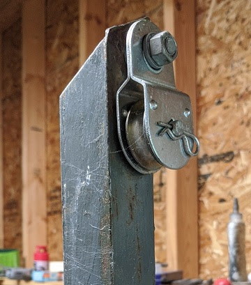
It is rarely a good idea to attach the hoist rope directly to the object being lifted since there are often sharp edges or bends that can trap and cut the rope. I typically use shackles, carabiners or tow straps to grab the item, and the hoist rope is attached to that.

On the left is a rope on a shackle. There are two problems to consider. The first is that the rope will slide to one end of the shackle pin, which is hard on the rope and may imbalance the load. The second is that the knot will tighten under load. For heavy loads the tight knot can be very difficult to untie on the tower at the end of the operation. You do not want to struggle with an impossibly tight knot 100' in the air.

In the centre picture, both problems have been addressed. With the pin fully occupied the shackle won't easily tilt to one side. The knot will also be easier to untie. The reason is that friction increases with every wrap of the rope around the shackle pin. The knot experiences less loading and will tighten far less. More wraps can be better if there's room for them. I will often select a larger shackle than strictly necessary just so that I can wrap more rope on it.

The type of knot becomes less important when you do this and mostly serves to keep the rope from accidentally unravelling. Two or three half knots often suffice. The cheap polypropylene rope in these pictures can be stiff and slippery! Woven rope will compress more and offer more friction.

Once I show someone the difference additional wraps can make when it comes to untying the rope, they rarely forget. It helps them on the ground and it helps me when they send a load up the tower.

Although the spring-loaded carabiner on the right is easier to attach there may be insufficient room for even two wraps of the hoist rope. The bunched up rope can also interfere with the operation of the gate. 

Carabiners are easy to use but can be weaker than a shackle. I have a habit of hiding the carabiners so that my helpers use shackles. But I will pull out a carabiner where they are the better choice. I have an endless supply of shackles of all shapes and size.

Where to tie the hoist rope

This one is very common since it is tempting to hoist an item by the fastener that is meant to support it once installed on the tower. Consider the Kellems grip for LDF5 Heliax in the picture. 

The grip is convenient for hoisting the Heliax. It can work very well since Heliax is pretty light and even for towers well in excess of 100' (30 m) the Heliax can easily support its own weight. Once at the top, the grip can be fastened to the tower while the Heliax is secured to the tower with cable ties or more professional fasteners. There is no good reason to remove it afterward, where it serves as insurance in case the cable ties fail.

It is understandable that someone will connect the hoist rope to the grip. You will not easily remove a hoist rope attached to the Kellems up on the tower while it bears the weight of the transmission line. They must be instructed or shown another way, such as a second removable grip or with rope using what some call a "thousand yard knot". The picture in that linked article isn't very clear but I hope you get the idea. The same method also works well on mast pipe.

Wrapping cable while hoisting

This item is closely related to the previous one. It last happened a few years ago when I was raising guys for installation on one of my big towers. 

Typical of steel guys on a ham tower, they are broken into lengths that are not resonant on any amateur band for which there is an antenna in the vicinity. Resonant guys act like parasitic elements that will degrade antenna patterns. The insulators and grips add considerable weight to the guys. On a tall tower the lift can exceed 100 lb (45 kg).

There is a guy grip at the guy station to which the guy will be attached. That leaves a short length of guy flopping in the wind above the top insulator. The hoist rope is typically attached to that insulator. One of the ground crew wanted to prevent the short length of guy from flopping around and striking the tower on the way up. He did that by slipping the hoist rope over it in the fashion shown in the picture. 

It worked well for that purpose but it posed a difficulty. There is no practical way to remove the guy from that knot. Steel EHS guy cable is not very flexible and the rope is gripping it with a lot of force. I had to send the guy back down with instructions to be less clever. It was an understandable mistake. You need to think ahead for how the knot can be removed.

One alternative is to twist a short length of wire over both the rope and guy. That is easy to remove. Tape or an expendable cable tie can also work. A similar technique can be used with long masts that where the hoist rope must be tied below the centre of gravity.

Overuse of a mechanical attachment

I have no pictures to illustrate this one so I'll try it with words alone. The situation is that I show up at a job site and look over the work to be done and the materials prepared for me to lift and install. I will often find a few oddities. Let me give one example. Once you understand the situation you'll be soon spot others on you own.

I was asked to raise a length of hard line up a tower. It had to be mechanically supported, grounded for lightning protection and connected to the antenna. The grounding kit for the cable was nicely prepared and the hoisting grip was laced onto the cable.

The problem was that all of it was intertwined. The Kellems grip was bolted onto the grounding clamp for the tower and the carabiner for hoisting was attached to the grip (see earlier section). With this arrangement, the weight of the transmission line would bear on the grounding clamp. The connector would be difficult to align and mate with the antenna connector and (as before) there was no way to make it all work with the hoist carabiner attached to the grip and grounding clamp.

This was an attempt to make my job easier. I appreciated the thought but not the implementation. I unbolted the grip from the grounding clamp and moved the hoist rope so it grabbed the hard line below the grip. We then hoisted it up the tower. I first adjusted the position of the connector so that it would easily mate with the antenna connector. Only then did I attach the grip to the tower. The weight was borne by grip.

With that mechanical connection secure, I attached the grounding clamp to another tower member, allowing it slack to remove mechanical stress on the ground wire and hard line. Only then did I proceed to screw the connectors together. After the transmission line and antenna were tested on the ground we sealed the connections and tied the cable along the tower on the way down.

Overloading one mechanical device to do several jobs puts stress where it shouldn't be and complicates installation and maintenance. If the load shifts over time there is a high risk of failure. Keep the electrical systems separate from the mechanical supports, and from each other. Co-dependency only seems like a good idea until you work through the steps for installation and potential failure modes as the system endures the elements.

Where to tie a tag line

There are many places to attach a tag line to a load. It is typical for a novice at tower work to tie it at the bottom (3). It is easy to pull the bottom of the load with tag line attached there.

But is that the best place for it? Take a look at the adjacent diagram for several options, using a large tower section as a heavy load.

Let's review the purpose of a tag line: to clear obstacles during the lift, such as guys, side mount antennas and wires, and tower protrusions such as bolts. The tag line should be attached so that the load can be safely and easily steered around obstacles. Since visibility is limited from a large distance, that can be difficult with tall towers.

This is a bit of a trick question since the answer depends on the lift method, length of the hoist rope and the shape and weight of the load. There is no one correct answer. A small, light load is easy to steer regardless of where the tag line is attached. On large, heavy loads it matters a great deal.

Tied at the bottom (3), a heavy load is easy to pull with the tag line, but the top of the load might hardly move at all. If the hoist rope is attached at the top (1) the load can be steered but more force is required the higher it is. 

If the hoist rope must be attached below the top, as it often must be for long loads lifted by gin pole, the tower section will pivot around the hoist rope attachment, That can turn the top of the load into the tower rather than pulling it away. When the load is near the top of the tower it may be impossible to prevent the tower legs from tangling with obstacles, including the tower struts. 

This can be especially dangerous when machinery is used for the lift. The machine operator (which may be a car for amateur station) must pay close attention and obey instructions. Assign at least one member of the crew to keep watch and with the authority to order the procedure to stop.

Tying the tag line to the top of the load requires more lateral force to steer the load. When the load is close to the top of the tower that will place a high bending stress on the gin pole or mast where the pulley is located. I have seen this happen too many times. I can assure you that it is a very bad idea. Gin poles are vulnerable to lateral forces, and I have seen them bend or break due to excess enthusiasm by inexperienced ground crew. I appreciate enthusiasm but skill and foresight are better.

There is no universal solution to the problem. Each situation must be thought through, step by step, so that potential problems can be anticipated and planned for. Two tag lines can be useful, one for when the load at a low height and another for when it's near the top. Where obstacles or loads are particularly difficult, I follow the load up the tower to do what a tag line cannot. 

On tall towers I will rig the hoist rope so that the load is on the leeward side of the tower. When it is on the windward side more muscle is needed on the tag line to keep the load free of obstacles. It is not surprising that this detail is often missed by ground crew. They tend to choose whatever end of the rope is convenient. 

One experience of fighting the wind pushing a big load into the tower is usually sufficient for the lesson to stick. Tag lines can't work miracles.

Horizontal pulley

I've been using a pulley at the bottoms of towers for a long time. They are used to allow a vehicle (or other mechanical device) to power lifts. Many of the crew who assist me like it for manual lifts since it is easy to allow multiple people to pull when the extra power is needed. It came in handy during COVID lock downs to keep them further apart. 

Pulling on a vertical rope is easier to rig but it only allows up to two to pull and they must stand close together. That small additional setup occasionally inspires someone forgo the pulley and simply pull on the vertical rope when only one person is needed for a lightweight load. 

That isn't necessarily a bad choice, but it must be done with safety in mind. Too many hams will haul the rope while standing next to the tower, and directly underneath the load. Disaster beckons! If you must pull vertically, stand outside the fall zone. Don't stand too far away when a gin pole is being used since that puts unwanted lateral force on it. A horizontal pulley reduces the risk to crew and equipment.

Coiling rope

After the job is done the tools must be gathered and stored. One of those tasks is coiling the ropes. I use very long ropes for hoisting and tag lines on my tall towers. They can be up to 100 meters long. That's a job I prefer to avoid! I am fortunate that there is usually someone who is willing to take it on.

There are many ways to coil long ropes. Professional riggers use weaved rope that can simply be stuffed into a large container without coiling. It is very expensive rope that does not have a preferred "twist" and can be stored that way since it will not kink or knot when pulled out for the next job. Hams rarely use rope of that quality and expense, so it must be coiled.

This is a 100 meter length of polypropylene rope. Although it rapidly decays outdoors (not UV resistant) it is effective, cheap, and expendable. I will happily replace it or cut it into shorter lengths when it inevitably degrades from mishaps or the elements. I have better rope in my stock in lengths up to 200' (60 m). I am always on the watch for deals on high quality rope.

Twisted rope will instantly kink if you spin it over your hand and forearm, which is what most people do. You can get away with that for short ropes but not long ones. Most discover the challenge very quickly and are eager to learn how to do it better.

One method is to draw the rope onto a reel. For long ropes that can be tedious unless you build a stand for the reel with a handle for turning it. Occasionally I've done it by hand and it is no fun at all. For steel hoisting cable like aircraft cable, this method is almost mandatory.

Another and more convenient method is to lay the rope on the ground while coiling it. For long ropes it saves time to make it a large (long) coil. After it is coiled, it can be folded over on itself once or twice for compact storage. It may then be cinched by wrapping one end of the rope around the bundle. So far so good.

The trouble comes at the next job. Can you remember how many times the coil was folded? You might but you probably won't if someone else coiled it. Was the end of rope used to cinch the coil unravelled properly to the needed length? Was the rope stored in a way that the loops would not shift and interleave? In short, uncoiling long ropes can turn into a nightmare even if you have the "schematic" for how it was coiled.

Predictability is key. Try to supervise rope coiling to the extent necessary to achieve this objective. It is also helpful to identify and secure the rope ends so they are not tugged on in a way that creates tangles when it must be uncoiled. Use a bungee cord to wrap the coil rather than use the rope itseslf. None of these measures will guarantee successful uncoiling but you will have better luck.

Alternatively, have the person who coiled the rope uncoil it for the next job. Try not to grin evilly when you assign them this job!

Cable spools

Lifting cable is easier when it is tied into a spool. It can be control cable, steel support cable, coax or other wire. In more complex installations it is needed above ground rather than always running down to the ground. For example, cantilevered strut supports, phasing lines for stacks, distribution of control lines, etc. The spool can be lifted or, if it is compact and light enough, carried up.

When the spool is lifted up the tower I find that the cable may not have been spooled in a way that is easy or safe to work with. For example, when the spool of cable is tightly held together with cable ties. It can appear to those on the ground that this is an effective method to keep the spool intact during lifting. Those cable ties need to be cut on the tower. When that's done, the entire spool springs loose. This can cause problems.

Several times the cable was narrow and the cable ties very tight. I don't often carry small snips for cutting the ties, and they can be quite tough if they're of high quality. Slipping the blade of a utility knife (which I always carry in the tool pouch) under the tie to cut it risks cutting the cable. I must not only be very careful, those high quality ties may require a lot of force to cut the tie. The cable may kink.

Once the ties are cut there is nothing to keep the loose cable from escaping control unless I am prepared and first loop it over my shoulder or a convenient and suitable place on the tower, if there is one within reach.

It is almost always better to use electrical tape to hold the cable in a spool. It holds well and it is easy to peel off. I can also remove one or two loops of the spool at a time and wrap the tape back over the rest of the spool to keep it secure. That's probably the easiest and cheapest way to send cable spools up the tower. It suffices most of the time. Cable ties may seem like a good idea in this application but it only looks that way while the spool is on the ground.

There's more (lots more)

Finding examples to use for this article was not difficult. I'm sure that many readers will think of other examples, or alternative solutions to the ones I presented. It is an educational exercise.

In closing, I want to emphasize that all of these situations and mistakes are not criticisms. Inexperience can lead any of us to the wrong conclusions. It happens more often than we might want to admit. All of us had to learn, whether by experience or by instruction from those with more expertise. It is not difficult to forget those hard won lessons while on the job!  

The willingness to stop and think ahead pays dividends when doing tower work. Indeed, the same can be said for most life situations we encounter.

Sunday, May 5, 2024

6 Meter Season Has Begun

It is interesting to me that in speaking of a beginning to the annual 6 meter season is less anachronistic than it ought to be. After all, here we are on the cusp of the peak years of solar cycle 25 when ionospheric 6 meters propagation should be common throughout the year. But that is just hyperbole --the truth is quite different. The F2 layer DX propagation that I saw during the far better peak of 1989 and 1990 was episodic and never routine.

Thus we continue to speak of the 6 meter season when sporadic E propagation marches towards its annual peak at the summer solstice in late June. I have already worked Europe via sporadic E (May 1) and more sporadic E openings, if only weak ones and with shorter paths, are already an almost daily occurrence. TEP linked propagation to South America occurs every few days even at my high geomagnetic latitude.

That said, this year's season appears likely to be different from those during the trough of the solar cycle. The reasons go beyond the rising solar flux index. It is worth reviewing those reasons now that DX propagation is beginning on paths other than the usual north-south TEP-assisted propagation between North and South America. It isn't just us, of course, since the same annual cycle of sporadic E is emerging in Asia, Europe, Oceania and elsewhere, and usually better than what we have in North America.

No matter the sporadic E expectations and the various predictions for the current solar cycle, working DX on 6 meters requires dedication and effort. It is never easy. Let's look at why this year may be different and why, I believe, better.

Digital

With regard to DX on 6 meters, digital modes have almost all of it. When you decline to operate digital modes you refuse the opportunity to work almost any DX at all. I've worked DX on CW and SSB over the past few years but it has been rare. That's the new reality no matter your like or dislike of digital modes. That ship has sailed.

The migration to digital has brought many benefits to 6 meter operation, and it also has brought annoyances. It is to be expected that more hams operating on a band will include a cross-section of the personalities in our hobby, which is really a cross-section of our societies. 

Although I enthusiastically embraced digital operation on 6 meters after initial misgivings, I strongly prefer the traditional modes. Each has its place in my ham activity. For example, when I participate in a VHF contest I solely operate CW and SSB. I appreciate that ARRL added the analogue category to their VHF contests. I do not enjoy digital contests on any band.

Increased activity

Many bemoan the lack of HF activity on most days. It is surprisingly sparse. Compared to decades ago, there are far fewer conversations taking place. Activity only seems to spike during DXpeditions and contests. The number of hams hasn't declined, it's just that preferences have changed. The conditions are there but not the interest.

With digital modes and 6 meter capability on rigs, amplifiers and multi-band antennas, the amount of activity on 6 has been increasing every year for at least the past 6 or 7 years. With more stations monitoring and transmitting there are more opportunities to make contacts and, important to many like me, to discover more openings. We now know that in the past many DX openings went unnoticed due to the lower activity and the difficulty of discovering openings on CW and SSB.

Additional enticements are DXpeditions. It has become routine for them to include 6 meters. They may only monitor FT8 most of the time and transmit only when propagation is likely. With internet connectivity they announce when and where they are CQing or monitoring for callers. 3G0YA is a recent example which successfully worked into at least the southern US. HD8M was worked by a few of my friends. I was busy when signals were at their best so I missed them. Expect several rare DX entities to be on 6 meters this summer.

Not all of the activity is always welcome. Consider the many robot operators. We can't stop them but we can make use of them. They are better than CW beacons since we'll hear the robots while monitoring the watering hole. There is no need to repeatedly spin the VFO knob to scan for beacons. 

It will not be long before regular 6 meter activity won't fit within the 3 kHz watering hole at 50.313 MHz. It already gets tightly packed during openings. That should not be seen as a problem. We can use the faster FT4 mode at 50.318 MHz or try the intercontinental window at 50.323 MHz. That is one way we can effectively spread out the activity. When a supplement to 50.313 MHz is eventually needed there is ample spectrum available. 

Over time we can expect that our rigs will accommodate digital channels far wider than 3 kHz, which is simply a limitation of the SSB mode that many of us must use with the current and older generation of equipment in our shacks. SDR rigs will be able to monitor multiple digital windows, one per receiver slice, without the clumsy workarounds that are currently needed.

We can and should accommodate more activity on 6 meters. The technology is already moving in that direction and the increasing number of operators migrating to the magic band demands it. The future is bright.

Chaining

The entire path doesn't need to be solar flux driven F2 propagation. By jumping from a sporadic E cloud at our high latitude to the higher F2 MUF or TEP at low latitudes it is possible to extend DX paths world wide. 

Crossing the equator to the south is easiest for us. It can be done even at solar minima, but DX to the east and west are more difficult. Chaining to low latitude propagation makes the path more likely. I expect better openings to Africa and Oceania in particular. Going over the pole by F2 propagation alone is unlikely in this solar cycle so that will continue to depend on relatively rare sporadic E. Chaining sporadic E to F2 over the pole is unlikely but it is possible. With increased activity this year the chances of discovering these unusual openings will improve.

Summer is not the best time for propagation on the high HF bands when absorption tends to be high. The same is true for F2 propagation on 6 meters. Since sporadic E is a primarily summer phenomenon, chaining is what we must hope for until the early fall when F2 propagation is better at this latitude, if the solar flux is high enough. It may be but there is no guarantee. Sporadic E will continue to be necessary for working DX over the next several months.

Solar flares

Solar flares are responsible for high x-ray radiation. Luckily the atmosphere protects life on Earth from most of the potential harm. One of the ways the protection manifests is x-ray absorption in the ionosphere when electrons are separated from gas molecules. The high ion density causes radio wave absorption on the sun facing side of the planet.

Flaring is associated with sunspots so their frequency and intensity increases a lot during solar maxima. As you can see from the following graph covering May 3 to 5, there are a lot of flares nowadays. Despite this, many DX and North American stations can still be worked on 6 meters.

The effect of flares is more keenly noticed at lower frequencies where HF blackouts occur. As you go up in frequency the degree of absorption declines. Depending on the flare intensity and duration there may be little to no discernible impact on 6 meters. You should take those blackouts as a sign to QSY to 6 meters. Don't be too quick to turn off the radio!

Geomagnetic storms

Flares are frequently associated with CME (coronal mass ejections). Fast proton streams can impact the Earth within a few hours (proton storms). Solar wind storms can take up to two days to reach us and cause high latitude geomagnetic storms. Both types of storms can disrupt propagation on HF and 6 meters.

Those at tropical and subtropical latitudes are less affected than those of us at higher latitudes. Europe is less affected than North America since we are closer to the geomagnetic pole. That said, unless there is an aurora there may be little effect on most sporadic E propagation paths. In the aftermath of a storm, there can even be enhancement of propagation paths between the north and south hemispheres. Aurora propagation brings an opportunity to work grids and states that are difficult on other propagation modes. This is one case where you must use CW or SSB.

Monitoring

In our busy lives we cannot constantly monitor 6 meters. Yet it is desirable since openings are not as predictable as on HF and they can be painfully brief, especially over long DX paths. This is a topic I've covered in this blog many times. 

Spotting networks have gradually become less valuable as a 6 meter monitoring tool as it has for digital modes on HF. It is so easy to discover all of the activity on a band by monitoring the usual water hole for a minute or two there is less incentive to spot. It may also be because it is less convenient to do so since WSJT-X doesn't support spotting so that a separate Telnet application may be required. Don't depend on spotting networks to discover 6 meter openings. Monitor 50.313 MHz.

This time of year when I'm not active on HF or away from home I leave the rig monitoring 50.313 MHz. I check activity occasionally and turn the yagi for likely propagation. I search the decode window to see if anything interesting showed up while I wasn't paying attention. I can also count on my friends to email me when I'm not in front of the rig. Monitoring the band has never been easier.

I don't really know why I am so popular but the act of simply monitoring is enough to attract callers. I glance at the monitor and notice that someone has been calling me for some time. You may be wondering how they know I'm listening. The answer is PSK Reporter. From my announced presence via WSJT-X, it is easy to discover that I am monitoring 50.313 MHz. They want to work me (for the grid?) so they call and hope for the best.

That strategy rarely works with me since I am most often doing other things while I'm monitoring. One near miss was FK8CP earlier this spring. I had called him a few times without success early one evening. I didn't hear him for a few minutes so I left the shack. When I returned several minutes later I discovered that he had been calling me for a few minutes. 

Of course it's far more likely that he made a delayed reply rather than finding me on PSK Reporter. However, you never know. Many of those we call rare DX consider VE3 to be an enticing catch on 6 meters. Monitoring can pay unexpected dividends.

Prospects

From all the positive indications I've touched on, I expect this 6 meter season to be a good one. How good remains to be seen. Last year's sporadic E season was relatively poor despite many of the same good indications. If you have been considering becoming active on the magic band, this year is an excellent time to do it.

I will consider the 2024 season to be a success if I can add 10 DXCC entities. It would be a spectacular season if I can add 20. Those are reasonable goals considering that my current total is 136 worked and 127 confirmed, accumulated since my return to 6 meters almost 10 years ago. Hope springs eternal.

I have a plan to make a modest improvement to my 6 meter capability this year. More on that in an upcoming article.