Friday, December 24, 2021

Lighting Up the 3-element 40 Meter Yagi

Lifting the 40 meter yagi onto a 43 meter high tower was not the end of the project. It was also necessary to design and adjust the feed system, and then test it on air. I can now confirm that the antenna works. However, the SWR is not what it should be, and that is worth a discussion.

I will start with a discussion of matching the antenna to the transmission line. After that I'll give my initial impressions from several days of use. You can skip ahead if that's the part that interests you.

Interaction mitigation

The reason the antenna elements are lightly loaded with capacitance hats is to defeat interactions with the yagis of the 15 meter stack. That is a particular concern when the 15 meter and 40 meter yagis are pointed towards Europe (northeast), which is likely to often occur during the years bracketing solar maxima. The siting of the towers has trade offs and I knew that I'd eventually run into issue like this.

As I discovered during modelling of the interactions, there is a difference between element resonance and system resonance. That is, the 3rd harmonic of the 40 meter yagi is different from that of each element in isolation. The yagi elements are of course tightly coupled and their mutual impedances determine the system resonance. Modelling is great but a measurement is better.

As the frequency increases any antenna will exhibit an increasing number of minor and major resonances. For this antenna we are concerned with any resonance near the 15 meter band. The VNA plot shows that the design successfully shifted the 3rd harmonic well above the 15 meter band. That's good! The modelling study suggested that pattern distortion of the 15 meter yagis due to the 40 meter yagi interaction with capacitance hats is well below that of interactions due to tower guys.

Measuring the pattern of a yagi is quite difficult so I am relying on the combination of modelling and impedance measurement. I tentatively conclude that I've accomplished my objective.

Gamma match design and challenges

The gamma match is the same one used for the experimental dipole. A few changes make it more suitable for the yagi. Initial adjustment of the gamma match was facilitated with a 500 pf variable capacitor clamped onto the gamma rod. The actual gamma capacitor is a length of coax inside the gamma rod. A long, cylindrical capacitor behaves differently and requires further adjustment to the gamma match.

There are effective methodologies to the design, construction and adjustment of gamma matches. Nevertheless it remain something of a black art. It is a very flexible matching system that can transform a wide range of impedances to the desired 50 + j0 Ω, however that flexibility can lead one to make poor choices. Yes, you may be able to achieve a perfect match at one frequency, but that does not necessarily mean that the match is optimum across the antenna frequency span. 

I have yet to find a gamma match design process or algorithm to accomplish the latter. Unfortunately I don't have one of my own to offer. This is a topic I would like to investigate when time allows. Until then I have to rely on vague heuristics, measurement and experiment. Unfortunately that is not easy at the top of a 150' tower. At least the driven element is easily accessible for adjustment, unlike HF yagis with 4 or more elements. For those big antennas you either lower the yagi to the ground to adjust them or you improvise.

The first SWR curve is quite poor. The DE (driven element) is tuned for resonance at 7.150 MHz. This is not ideal since the gamma rod length and gamma capacitor value are larger than I'd like. After re-reading several technical resources, I realized that it is better to have at least -20 Ω or more of capacitive reactance at the centre frequency, just as for the beta (hairpin) match. Although the antenna has good performance from 7.0 to 7.3 MHz, the centre frequency for matching should be 7.1 MHz. There is insufficient capacitive reactance in the antenna as designed.

Modelling confirmed that adjusting the length of the DE changes X without any significant change to R. Changing the resonant frequency of the DE (within quite a large range) has no effect on the gain and pattern, despite the common belief of many hams. Yagi performance is almost entirely determined by parasitic element reactance at the operating frequency and position relative to the other elements.

The DE was shortened by 12" (30 cm) on each half element by sliding the ½" tube into the ⅝" tube; the ¼" tips are less adjustable so they are left alone. The change raises the resonant frequency from 7.150 MHz to about 7.350 MHz, which should add at least -20 Ω to X. Making the adjustment involves rotating the DE on the boom, climbing down the tower ~30', hanging out from the tower to make the length adjustment, and then repeating the process for the other side of the DE. 

When I first tried adjusting the DE length the wind was very strong, the temperature near freezing and the element tangled in one of the guys when rotated for the second half-element adjustment. I gave up and completed the adjustment a day later with the antenna rotated a few degrees to clear the guys. The SWR curve was much better, ranging from 1.4 at 7.0 MHz to 2.8 at 7.2 MHz, and 1 at 7.090 MHz. Unfortunately my phone glitched and the picture of the analyzer screen is lost, so you'll have to take my word for it! 

Even so the SWR bandwidth is less than what is possible with full size elements. My modelling indicated otherwise but I suspected that was optimistic, careful scaling notwithstanding, because NEC2 inaccurately calculates the reactance for complex antenna shapes, such as the capacitance hat loaded elements of my yagi. The 2:1 SWR bandwidth ought to be better than 150 kHz.

The feed point as currently implemented is quite simple: the gamma match and a bracket with the UHF jack. The RG213 rotation loop to the Heliax transmission line was already there from previous antennas that were on the 150' tower. The weatherproofing was completed after the photo was taken.

Notice that there is no common mode choke. It was expedient to exclude it even though I have a commercial unit on hand with coax wound on a ferrite torroid. Gamma matches are said to inherently provide a measure of common mode rejection, but I have never verified the truth of that. Although a choke is highly recommended it is perfectly possible to escape its ill effects with no measures taken. I will add one next year even though I notice no ill effects.

The gamma rod is a telescoping 6' long ⅝" tube inside a 4' long 0.84" OD pipe. When moving the strap between rod and element I keep the strap bonded to the ⅝" tube and trombone it inside the pipe. Because the final strap position is further inboard the pipe is almost superfluous. It also means that nearly the full length of the gamma capacitor's outer "plate" is the ~½" ID of the ⅝" tube. It is a good fit for RG213 sized coax with an outer diameter of about 0.4". Perhaps I will get rid of the larger pipe and adjust for the different step up ratio due to a narrower rod. If I'm lucky the change will be helpful.

RG213 is a poor choice in this application. Unlike the gamma capacitors of my higher frequency yagis, I use the outer conductor (shield) of the coax as the inner capacitor plate. The problem is that the jacket of RG213 is typically plasticized PVC which is a poor dielectric at HF. The inner conductor surrounded by the PE dielectric, stripped of the braid and jacket, is superior and well suited for this application. The expected loss of PVC at 7 MHz is not high but it makes little sense to go to the trouble of building this antenna and making compromises.

A better choice is LMR400 due to its PE jacket material. The jackets of both are infused with carbon black but not enough to be a flash over risk. The ID of the gamma rod and the dielectric constant are important parameters when constructing a gamma capacitor of this type. Here's what I measured:

  • RG213 (PVC) inside a 0.622" ID pipe: 4.7 pf/in (1.9 pf/cm)
  • RG213 (PE dielectric, stripped of braid and jacket) inside a ½" ID tube: 2.1 pf/in (1 pf/cm)
  • RG213 (PVC) inside a ⅝" OD tube: 8 pf/in (3.2 pf/cm)
  • LMR400 (PE) inside a ⅝" OD tube: 5.7 pf/in (2.3 pf/cm)

Voltage across the gamma capacitor is a concern since it can be quite high. The lower the capacitance the higher the voltage across the capacitor. Using TLW to develop an approximately equivalent L-network of the same topology and impedance transformation there is ~700 volts at 1000 watts. The LMR400 jacket is sufficient provided that the far end of the coax is well taped or similarly insulated. So far it is working well although that might change if water enters the gamma rod. I sealed the rod to prevent that from happening.

Proceeding with the last of these options, I used 60" of LMR400 with a measured capacitance of ~330 pf. By a combination of trimming the coax and telescoping the gamma rod I got the ~295 pf needed. Unfortunately the final SWR curve is not as good as with the variable capacitor.

There are two differences between a fixed position capacitor and the cylindrical gamma rod capacitor that may account for the degraded SWR curve:

  • As you telescope the large, inner pipe to reduce capacitance (more -X) the wire from the connector to the capacitor get longer (more +X). That makes adjustment more difficult and alters the frequency-sensitive behaviour.
  • The gamma rod capacitor is only ~1.5 meters long, but that is long enough to exhibit transmission line effects. Assuming a velocity factor of 0.7 for the jacket, the LMR400 section is over 18° long at 7 MHz. The effect is not large but it is frequency sensitive and the overall impact is difficult to calculate.

All that said, the antenna works. It is cold up there and I had had quite enough for the season. I declared it to be "good enough" for ham work and climbed down for what I hope is the last time this season. The inconvenience of a less than perfect SWR is tolerable until I can deal with it in the spring sunshine.

On the air: initial impressions

Achieving gain on 40 meters is challenging for most hams. For several years running, the most popular articles on this blog are those about 40 meter wire yagis. Articles about bigger antennas may be interesting reads but few hams would contemplate undertaking those projects. Small rotatable yagis with shortened elements, like my Cushcraft XM240, are more common but still a relative rarity.

This 3-element yagi is a revelation. It is performing beyond my expectations. Part of that is the height but I don't remember the XM240 at the same height doing so well. DX signals in comparison to the XM240 at half the height are pretty well without exception stronger. Sometimes by a little and often by quite a lot. Switching back and forth has become one of my favourite activities for the past few days.

Most hams in this region find that there is usually little difference between signals from Europe for the same antenna at 20 meters and higher. The typical elevation angle for the path is 10° to 20°. That is not the case between the XM240 and the 3-element yagi. At worst signals are the same strength. At best European signals are 3 to 4 S-unit stronger. That's a remarkable difference.

As the path length increases the average difference between the antenna is more marked. During our wintertime late afternoons long path openings to east Asia many stations can be heard and worked. A simple CQ is usually enough to attract several callers from Japan. The XM240 at the same height didn't do half so well. Flipping between the antennas, many of these signals virtually disappear on the XM240. It is true for Europe and other directions as well: signals that are barely discernible on the XM240 are solid copy on the 3-element yagi.

I have been having fun this week! The antenna coming online now is like a Christmas present to myself. I keep telling the friends who helped me raise the antenna to come over and try it out. None has as yet, but perhaps a few will once the holidays are over.

I expect the antenna to pay dividends in DX contests to come. My plan is to reserve the XM240 for North America and DX paths off the direction of the bigger antenna. 40 meters has been my most problematic band during contests and that is going to change. This antenna puts a smile on my face. After close to 50 years with a ham radio license it is rare that anything in this hobby can do that.

Improving the antenna

The SWR needs attention. I need it flatter across the band to be compatible with a solid state amplifier. With my current manually tuned tube amps it is not a problem up to 7.2 MHz other than having to touch up the tuning when QSYing more than about 25 or 30 kHz. Ideally, the SWR should be below 1.5 from 7.0 to 7.2 MHz. The antenna does not need to match well above 7.2 MHz since that 100 kHz segment is only used in our ITU region, so the lower XM240 is good enough for the shorter paths.

I will first try variations of the gamma match. Since the voltage across the gamma capacitor isn't very high I may try a fixed position capacitor, fixed or variable, to equal or exceed the better SWR found during the adjustment process. Alternatively, the gamma match can be optimized for CW (7.0 to 7.1 MHz) and install a switched L-network to improve the SWR between 7.1 and 7.2 MHz, and perhaps another for higher than 7.2 MHz.

If I put the gamma capacitor in a box I will have room for an L-network. It has to be an L-network since varying the capacitor value isn't good enough. The R component of the impedance dips too far below 50 Ω as the frequency rises.

Another parameter to be adjusted is the DE length. More capacitive reactance by further shortening the DE may help. Certainly the SWR bandwidth improved by raising the DE resonance 200 kHz, as described above, and it is reasonable to think that a little more can be helpful. It is not so easy to determine the DE reactance to achieve the broadest SWR bandwidth. I have not yet found a definitive technical resource that addresses the issue.

As a last resort, I will take down the DE and convert it to a split element. More matching options become possible at the expense of a more complicated mechanical design. I do not foresee adding a coupled resonator (4th element) to make it an OWA yagi. That would add another 9 ft² of wind/ice area and the capacitance hats might get too close or touch in the breeze.

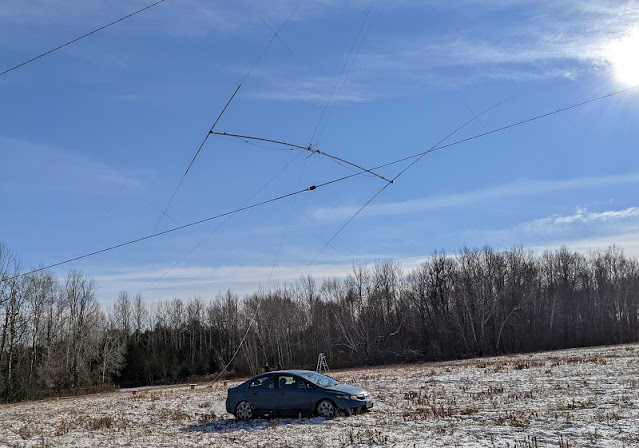
I'll close with a annotated picture of the antenna farm that includes the 40 meter yagi. The elements are slightly askew and the boom is not aligned with the 10 meter yagi above it. These are simple to fix but will be delayed until spring. The picture has been uploaded to my QRZ.com page.

Have a merry Christmas and a happy new year. There may be one non-technical article to come before 2022 arrives, but no promises.

Thursday, December 16, 2021

The Mother of All Tram Lines

The title is the answer to the following question: how do you lift a 300 lb 3-element 40 meter yagi onto a 150' tower?

When we last saw this new antenna it was partially assembled at the launch point for raising onto the tower. A lot of work has gone on since then. There is a great deal of preparation required for a lift of this magnitude go smoothly and safely. I am happy, and relieved, to report that the antenna is on the tower and working. It has already been subjected to high winds and survived the experience.

We need to rewind a few months to understand how I proceeded to design and build the tram line to bring this project to fruition. Don't expect a full blueprint, just enough detail to give you a good idea of how to do it. This is not a project for a novice. Mistakes can be lethal. How?

  • If insufficiently strong without supports (e.g. boom truss) the antenna can break, fall and damage the rigging.
  • Steel cables under tension will whiplash at high velocity if they kink and break, a mechanical connection fails, or a winch or come-along fails. The cable can maim and kill.
  • The tower, mast or ground anchor can fail if improperly engineering or used. Property damage is guaranteed, and life is also at risk. No, you can't run out of the way fast enough and a hardhat won't save you.
  • A falling 300 lb antenna striking a guy wire will very likely bring down the tower. See previous bullet.
  • A vehicle hauling an antenna up the tram line has sufficient power to break the tram line, haul cable, mast, pulley blocks and mechanical connections if it happens suddenly and power is not removed immediately. See second bullet.
  • No matter what you say, crew members (and probably you as well) will remove personal safety equipment and step under the antenna and rigging, usually for no justifiable reason. There is no good reason except under strictly controlled conditions.
  • No one should be on the tower during the lift. Leave that until after the antenna is in position and all but the critical cables are slack. If you must be up the tower to facilitate the lift you're doing it wrong.

A professional rigger who loaned several items that I needed for the tram said that for commercial work they strive to use cables, ropes, tools and fasteners at no more than 10% of their breaking strength. This is very conservative since 20% is more typical. When you consider the liability for injuries and property damage for failures of large towers and while lifting heavy loads up those towers the conservatism is well justified. As a ham I am willing to venture higher than 10% but rarely more than 20%. At 30% the alarm bells should be ringing no matter who you are or what you're doing. Don't even think about it.

Amateur radio is a hobby. Be conservative and be safe. There is no shame in admitting a procedure is beyond your ability. Hire professionals.

Do you feel suitably chastened? Sorry to put you through that but it really needs to be said. Repeatedly. In my long experience too many hams have misplaced optimism. 

Note on photos: Most of the best photos in this article were taken by Alan VE3KAE. He came over several times to help with antenna and rigging assembly, rigging tests and for the final lift. The worst pictures are by me and my not very good smartphone. I don't show credits on each photo. I also have a new phone that I'll try on upcoming projects.

Taking the time to get it right

I started the rigging in October and the lift was done on December 1. I proceeded carefully, taking all the time I needed to be absolutely certain. I am no novice but this is not a job to be done rashly.  We then waited for agreeable weather, and the weather is rarely cooperative this time of year. 

I cancelled the first scheduled lift day because I wasn't fully satisfied with the rigging. That was easily remedied but a week passed before acceptable weather returned. There was also snow on the ground.

The setup

A lot of space is needed for the big tram. The diagram below has been supplemented with an aerial view (overlaid on a Google satellite image) and photos of critical components.

The tram line anchor on the ground is a large tree wrapped with chain. The upper end of the tram line is halfway up the 10' mast and is comprised of several commercial rounded mast plates. Due to the required force to withstand the weight of the antenna and tram line and the tension of the tram line and haul cable there is a back stay. The back stay is essentially a temporary guy. I was lucky to find a suitable tree (large and healthy) that is ~1° off a direct line through the tower. The mast pulley is placed on the other side of the mast to compensate, but that wasn't really necessary.

The haul cable is 500' long to traverse the large distance from the launch point, over the tower to the guy anchor and then horizontally to the vehicle. My preference was to have the haul cable run straight down the tower, as I've done many times before. That required a cantilever and second pulley that would be under high stress. Taking the cable outward from the tower is easier but adds complication during the lift, as we'll see later.

The overall procedure is to crank the winch to lift the antenna far enough that when the haul cable is pulled tight the rear tips of the long elements don't strike the ground. The back stay is tightened to keep the mast vertical. The antenna is hauled up until the forward tips approach the forward guys. The tram line is again tightened and the tag line pulled to tip the element to be more vertical. When the antenna reaches the tower the tram line and back stay are slacked so that the boom rests against the mast plate. We climb the tower and bolt everything together.

There are two lifts. The first is the antenna without the driven element. That reduces the weight to less around 250 lb, which includes the rigging. It also prevents severe interference between the driven element and its fragile capacitance hats, the cables parallel to it, the tower and mast, and the 10 meter yagi at the top of the mast. The driven element is lifted end first, just as it was for the dipole that was lifted last year, and taken down the same way earlier this fall.

That's the summary. Details follow.

Equipment choices

EHS 7×1 guy strand is not ideal tram line material because of the bend radius imposed on it by the antenna weight pulling on the tram line pulley blocks. However it is strong and I have a lot of it scavenged from commercial towers. The tram line and the tram line extension to the anchor is ¼" EHS. The extension is needed since the longest length in my stock is 200'. It is the same cable used a year ago to tram the 5-element 20 meter yagi to the top of the 140' tower.

The breaking strength of ¼" EHS is 6000 lb. Tension during the procedure never exceeded 800 lb, or 13% of breaking strength. The winch is rated for a 1750 lb working load and its cable is ⅛" aircraft cable with a breaking strength of 2000 lb. A come-along was used on the tram line when the tension exceeded 400 lb (20% of breaking strength). Shackles, chains and other cables in the rigging are used within their working load limits.

The haul cable is 500' of 7×19 3/16" aircraft cable with a breaking strength of over 4000 lb. A smaller cable could have been used since the weight it would have to support is no more than 250 lb. I followed the advice of the professional to buy the bigger cable as a safety margin, both for the lift and in case there was tangling with the rest of the rigging.

Rigging the antenna

For the initial test of the rigging the connections to the antenna were partially improvised. I used materials that are easy to work with but that are not of adequate strength for the lift. Once we were satisfied with the overall setup, stronger materials were substituted.

With the first version of the rigging the antenna was lifted by the winch. The element tips and capacitance hats were not attached to protect them during the trials. As the tram line is tightened the antenna moves backward and can spear the element tips into the ground. The tips, though tough enough on their own, cannot withstand the weight of the antenna bearing on them. I had a friend (Alan VE3KAE, seen below) help with the test of the rigging.

Notice the bowing of the boom. The boom must support its own weight of 110 lbs and 45 lb of element and clamps at each end. The boom can withstand the static stress. It is important to install the boom truss as soon as possible after it is on the mast since the boom isn't likely to survive a high wind without it. On its own, it can handle the weight or the wind load, but probably not both.

The antenna is unbalanced in this test. The reflector (nearest element) is heavier than the director by about 3.5 lb, and about 4 lb with the tips installed. Finding the centre of gravity (CoG) by experiment alone is tedious so I developed a spreadsheet to calculate the moment on each side of the tram line. When the antenna was assembled and the exact CoG found, the calculation was off by just 1". Balance helps to steer the element tips clear of the top guys and the 10 meter yagi atop the mast. The 10 meter yagi is 24' long, which is only half the boom length of the 40 meter yagi, so the reflector and director clear the 10 meter antenna with room to spare.

Below is the final rigging of the boom. It is worth describing a few details.

The are two ¼" commercial steel plates to secure the rigging to the boom. One chain attaches to the tram riding trolley and the other to the haul cable. The chain for hauling is shackled to the plates. When the cable is pulled the plates align with the tram line and that tips the elements up. The trolley is ½" steel plate with shackles to hold the pulley blocks that ride the tram line. 

Although small, the pulley blocks are rated for a few tons of working load. I used two to spread the load on the EHS, to reduce deflection and point stresses that can damage the cable. After the rigging was dismantled I found a couple of small kinks near the bottom of the tram line, where the trolley was positioned most of its time the antenna was off the ground.

The truss cables and turnbuckles are tied together and to the boom plates, and held to the boom with cable ties. It is important that they don't escape or the antenna would probably have to be lowered to retrieve them. After it is raised the extra rope length is looped over the tram line to keep the truss half tied together and free to reach the mast clamp.

The light duty steel angle and attached tag line are used to tip the elements further upward to clear the top guys. After the boom is bolted to the mast plate the angle stock is a lever to rotate the boom and level the elements. The alternative is to wait for the driven element and use that as a lever.

The lift

The tricky parts of the lift are the beginning and the end. Watching the huge antenna slide up the tram line is awesome but requires no work other than keeping in communication with the driver. The first step is to lift the antenna by pulling in the slack in the tram line. During this process the tension rises only slowly. We stop when the winch is too difficult to turn or the tension reaches 400 lb. There is a Loos tension gauge on the ¼" EHS tram line extension cable. The come-along is attached to the extension cable with a sacrificial pre-form and the tightening continues. 

What we're really doing is raising the antenna rather than increasing tram line tension. That is because the antenna is so far along the tram line. The loading is very different when the launch point is closer to the ground anchor and when the antenna approaches the top of the tower. It was interesting to watch the tension gauge hold steady as the tram line is tightened. That isn't what most people expect to occur.

Once the antenna is a few meters off the ground the car rolls forward a foot or two to take the weight of the antenna. One person watches each rear element tip to keep them from spearing the ground. When it's high enough we spread the capacitance hats.

I confirmed in the model that the hat arms don't have to be at exact right angles to accurately reproduce the loading effect measured last year. We did it anyway since it looks prettier that way. Helping me out (above) are fellow contesters Vlad VE3JM (left) and Greg VE3PJ (right).

We did have an accident when one of the arms broke. I believe it was the arm that snagged and bent when it was lowered from the tower earlier this fall. An hour was spent building a new one. Before resuming we stopped for lunch. The antenna was left hovering above the ground.

John VE3NJ is driving his car in reverse to haul the antenna because the tow hooks are at the front of the chassis. The car may seem small for the job but it is in fact perfect. The peak towing load is only slightly more than the antenna weight and that is only reached when the antenna nears the top of the tram line. The engine's moderate torque capacity gives the driver an excellent "feel" for the load and mechanical snags that might occur. 

The automatic transmission is particularly helpful to control torque and avoid sharp acceleration and deceleration. My car has a manual transmission which makes torque control difficult. I salute John for his willingness to drive into the snow filled hay field.

The unevenness of the hay field caused some difficulty. Two of us had to push the car when it entered a small depression and the drive wheels spun in the deeper snow.

The tension on the tram line drops to a low value as the antenna approaches the top of the tram line. That can come as a surprise. The weight of the antenna at this point is almost entirely on the haul cable, so the tram line carries less of it.

The partially slack tram line must be tightened at this time to raise the antenna to help it clear the top guys and the prop pitch motor platform (it's the blob just below the top guy station). Turning the winch crank quickly raises the tension, so we again switched to using the come-along on the heavier EHS. A guy grip locks the tram line to the chain around the anchor tree. The back stay must be adjusted to compensate for the increased lateral force on the mast.

I put most of my weight on the tag line to raise the forward tips well over the top guys, while at the same time shouting instructions at John (with others relaying my words through the car window). We all had radios but without VOX I can't transmit when both hands are occupied.

The boom briefly tapped the top guys and then cleared the prop pitch motor. The boom bumped into the top few inches of the tower but in a moment it was over the top. We slacked the tram line and back stay so that the boom hung straight down at the level of the mast plate. 

The top safety rope now comes into play. Look at the top diagram to visualize the forces at play. With the tram line and back stay tension eased, we are left with the lateral force of the haul cable due to the ground pulley being 120' from the tower base. The safety line is there in case the mast bends backward more than I'd like. It turns out that it wasn't so bad and the safety line may have been unnecessary. Knowing what might happen is why I took this precaution. The inset photo (diagram above) shows the mast rigging after the safety rope was moved out of the way of the truss clamp.

Securing the antenna

I climbed the tower with the 4 u-bolts to attach the boom to the mast plate. It was remarkable that I had to instruct John to lower the antenna only 1" to align the boom with plate holes. They went in with no drama at all. The antenna was secure at the top of the 150' tower. The car moved forward to fully slack the haul cable.

The chains from the tram line trolley and haul cable were removed and the tag line transferred to the trolley. I sent the lot of down the tram line. With the tram line slack, the dangling chains strike the ground to slow it down and prevent damage. 

Free of the pull of the trolley and haul cable, the boom was rotated with the lever. The elements couldn't be completely levelled until later when the rigging plates on the boom were removed. That was done after the boom truss was connected to the mast.

The position of the rigging plates up the mast made it difficult for one person to attach the boom truss cable to the mast clamp. Vlad VE3JM joined me on the tower to lend a hand. One of us pulled in the truss cable and the other drove the bolt through the clamp and turnbuckle eyelet. We then levelled the elements. By tightening the turnbuckles we levelled the boom. 

The sun was setting so that was it for the day. We took pictures, climbed down and my friends left for home after a very productive day.

These are the pictures Vlad and I took of each other, and one that Alan VE3KAE took of us from the ground. They make a pretty mosaic.

Driven element

The weather worsened so we could not raise the driven element for two weeks. During that time we had two wind storms, one of which hit on Dec 11 with gusts of 100 kph and higher. My imagination did run a little wild since it was nighttime and I all I could do was listen to the wind roar for several long hours. In the morning light I was relieved to see that the antenna and tower were unharmed. The tower and antenna are designed for survival, but that never completely allays one's fears.

Wind on the scheduled day was gusting to 50 kph on the ground and higher on the tower. We went ahead because there was a problem finding a day with better weather when I could gather enough helpers. Good tower work weather is uncommon this time of year. For this last step we were the same group as before, less one person. 

The wind was really strong so we had to alter the rigging to lift the driven element safely. It is going up end first and by muscle power using the same tram line. The steel haul cable was replaced by rope since it is far easier to work by hand. It went up end first to thread the triangular gap between the boom, mast and boom truss. The leading capacitance hats are only unfurled once they're through the gap. That was my job.

The element was whipping around so much that I tied the haul rope to the leading edge of the element 1" tube just inboard of the capacitance hats. With that simple addition the tip pointed straight ahead and parallel to the tram line. The tip points at the mast where the tram line anchor and haul pulley are mounted. I removed the wire and gently pushed the capacitance hat arms around the mast.

There were tense minutes after I saw that the capacitance hats were above the tram line and a fix was required. At some point near the ground, when the element was swinging in the wind it someone twisted up and ended up on the wrong side of the tram line without any of us noticing. 

Choreographing a few acrobatics with the capacitance hats I was able to get them back under the tram. Hauling continued until the element-to-boom clamp was on the boom. Getting that 60'+ element steady enough in the gusting wind to thread the u-bolts was a challenge.

With the element bolted down I loosened the boom and used the driven element as a lever to better level all of the elements. I couldn't yet slide the DE into its correct position because the slack tram line was lying across it. It was getting late so we called it a day. The sun set early this time of year.

The next day I dropped the tram line on my own and slid the DE to its position on the boom. I then did the first test of the SWR, using a variable capacitor in place of the capacitor inside the gamma rod. The measurement after adjusting the capacitor indicated that the antenna was behaving as a yagi, but with a couple of surprises. 

More on adjustment and getting the antenna on the air in a future article. The weather this week has been continuing warm, if wet and windy at times. I have to move quickly to beat the weather. The rigging is now been completely removed from the tower, and work on the yagi feed is ongoing. Whether it works or not the antenna is going nowhere until warm weather returns.

I'm pushing it to the deadline but this antenna will be working and on the air this year and before the serious winter weather rolls in. This is the pinnacle moment of my 2021 station plan and I intend to get it done right and on time. I let other items slide but not this one.

While the work was going on we were so wrapped up in the details of getting it done that it was easy to forget how big this thing is. It is no surprise that very few hams have a 40 meter yagi with 3 or more elements. It was a shock to look out the window the morning following the big lift and see that monster perched at 150'. It's impressive and intimidating. However, an antenna is meant to be used and not merely admired as an ornament. 

I hope that this story about large antenna tram lines has been of interest. Not many would choose to raise an antenna of this size without hiring a crane.

Friday, December 10, 2021

Contesting on 160 With Receive Antennas

Contesting on top band with directional receive antennas has its challenges. Before delving into that subject I will first review the fundamentals of antenna reciprocity, and its close cousins: power, noise and antenna efficiency.

Reciprocity

Antennas for the most part are reciprocal: they work the same on transmit and receive. A non-directional antenna transmits and receives equally in all directions. A directional antenna favours one direction for both transmit and receive.

There are a couple of provisos to this fundamental rule:

  • Efficiency: An inefficient antenna can receive as well as an efficient one but the inefficient one transmits a weaker signal in all directions (mimics lower transmitter power)
  • Noise: Man made or atmospheric noise degrades reception (SNR, or signal to noise ratio) in all or some directions while having no effect on transmission

Efficiency and noise along with power and receiver sensitivity determine the effectiveness of communication with another station. For this discussion we'll set aside the communication aspect of the subject, despite its importance, so that we can focus on reciprocity.

Antenna efficiency is not typically an issue on the high HF and VHF+ bands, especially with horizontally polarized antennas above the roof or tree line. Verticals on the low bands can be efficient when in the clear and with lots of radials to minimize ground loss in the antenna's near field. 

Need for and use of directional receive antennas on 160 meters

Inefficient antennas are common on top band since horizontal antennas are necessarily low (with respect to wavelength) and verticals are usually short and have insufficient radials. The consequence is that you hear many stations that cannot hear you.

Let's assume that you have an efficient and effective antenna for 160 meters. You might also want to use high power to further the likelihood that others will hear you. Noise of all kinds is a problem for everyone on 160 meters. That efficiency and power guarantees that you will not hear many stations that copy you very well since their antennas are less efficient.

Few antennas on top band, even the full size efficient one, are directional. Verticals are omni-directional and horizontal antennas like inverted vees are nearly omni-directional, and what directionality they have is modest and usually not in any favoured direction. You just put up what you can.

For a contester like me this is a problem. My 160 meter antenna is efficient and omni-directional. When I turn on the amplifier I know that there will be many stations that will be frustrated by not getting my attention. Of course I don't know that they're frustrated, because I can't hear them, but I strongly suspect that I'm losing many potential QSOs.

There is way to overcome the reciprocity challenge and that is with a directional antenna. With a high RDF (receive directivity factor) more of those unheard stations will be heard. Unfortunately a directional and efficient antenna on 160 meters is rare because it requires two or more elements and lots of radials, and that entails a lot of land and expense.

The alternative is an omni-directional and efficient antenna for transmission paired with a directional receive antenna. The receive antenna can be small and inefficient since the atmospheric noise is high; that is, an inefficient antenna can improve the SNR while being sensitive enough to hear signals at the noise level. For the smallest and therefore most inefficient receive antennas a 10 db to 20 db pre-amp may be needed.

Contesting with a directional receive antenna is different

Using a directional receive antenna for regular DXing isn't complicated. If you're responding to a spot you already know the heading of the desired station. You choose your receive antenna and there it is. Occasionally there is skew path, long path or an anomaly with signal polarization that requires a different selection. 

When you CQ DX you have a general idea where to expect signals from and you choose that antenna direction. You know because of experience, paths that are in darkness, location of the terminator, population centres and other factors. For example, at our sunrise openings in winter the most likely directions are west (Oceania) and north (east Asia). It is a good idea to check northeast for Scandinavia and northern Russia.

In a contest signals can come from any direction. When you run with a big signal you will be called by stations in Europe, the Caribbean, South America and all over North America for most of the evening. Getting the direction right for every caller is not easy. This matters because speed counts in a contest. They might not even try twice if you fail to answer them on their first call. They also value their time.

The plot at right compares the azimuth patterns at 20° elevation of an 89 meter and a 156 meter long Beverage under the same ground and height conditions. As you can see the longer Beverage has greater directivity (and gain), with an RDF or about 10.5 db vs 8.5 db for the shorter Beverage. Side and rear rejection is poorer for the shorter Beverage. Top band DXers would prefer the antenna with the higher RDF. A contester sees it differently.

For a higher directivity (RDF) more receive antennas are needed to effectively cover all compass directions. In my Beverage system I am aiming for 8 directions with 4 reversible antennas -- I have 3 antennas and 6 directions at the moment. More directive arrays require more directions, such as 8-circle and 9-circle vertical arrays. A compact K9AY switched apex loop antenna can get by with 4 directions, at the price of a lower RDF.

The critical question for my contesting operating is: how many directions do I have to test until I can find or copy a signal that is at first weakly heard or entirely inaudible? Ideally I would like to not have to switch at all to save time and repeat requests. That is equivalent to omni-directional receive, which we already know doesn't solve the basic problem: copying signals that require an RDF boost from a directional antenna.

In last weekend's ARRL 160 Meter contest I regularly had to ask for repeats until I successfully found the right direction. My big signal attracts many smaller stations. When I operate QRP I rarely need to use a receive antenna.

On the plot above you can see that the F/S of my longer Beverages is high. The F/B is also quite good but not so extreme that I can't hear most stations off the back. For example, if I'm listening west I am more likely to hear a caller from Europe than from Florida to the south.

To minimize hunting I would often stick to the the NE-SW Beverage, pointing to Europe when conditions were favourable and southwest the rest of the time. It's a compromise that while not ideal places the side nulls where they do the least harm. When I heard nothing after a CQ the reverse direction was selected. I can thus hear south and west well enough to catch most callers. The nulls of the preferred N-S and W-E Beverages totally reject signals from too many callers. Once I fully copy the call sign of a particularly weak station I would select the Beverage in the correct direction. 

Later in the evening when west coast signals improved my strategy was to flip between west and south, which was good enough to receive most US callers, and then northeast for possible European callers, especially at their sunrise. With my rudimentary and allegedly temporary Beverage selector it was hard on the fingers after several hours of operating.

Unfortunately call signs are deceiving. There is no association between call signs and call districts in the US. Many was the time that I'd struggle with a weak W7 only to discover they were in Virginia. Switching from west to south would bring a barely audible signal up to S9. Some of them must have wondered why I seemed so deaf. A trick I latched onto was to space over the exchange field in N1MM Logger+ when I had a full call to see if their ARRL section was in the history file. That helped me narrow in on the correct direction.

With a shorter Beverage, an end-fire vertical array or a compact loop the F/S is quite poor. That would reduce the number of repeat requests since a weak caller is more likely to be copied on the first call than with a Beverage. The price is a lower RDF. It is an interesting question whether a high or low RDF receive antenna is more costly with respect to QSOs and rate. I don't know the answer.

There's more to it than a simple RDF figure since there is more than one RDF per antenna. The pattern is 3-dimensional and the azimuth pattern can vary a lot with the elevation angle. As repeatedly stated in ON4UN's Low-Band DXing, when you choose the length of a Beverage or the element phases of a vertical array you are also choosing the azimuth and elevation angle where the nulls appear, and at which frequencies. A knowledge of propagation from your QTH can help to make those choices. 

However, it isn't easy to figure that out and I have never tried. The elevation patterns of the Beverage (above left) and end-fire array (above right) are interesting, though not shown here. It is usually enough to pick antennas with approximately useful patterns and RDF. Obsessing over the details is rarely worth it. But do beware those nulls when your objective is contesting. The 3D plot of a short Beverage illustrates some of the complexity we must deal with.

Alternatives

The objective in a contest is to copy the call sign of the station quickly and accurately no matter their direction or signal strength. With that information you can select a direction or antenna to peak their signal for the remainder of the exchange. There are several alternative approaches, from simple to elaborate and expensive.

Directional transmit antenna: Reciprocity is restored when you transmit and receive on the same directional antenna, just as you do with a yagi on the higher HF bands. Unfortunately a directional and efficient transmit antenna on 160 meters is very large, very expensive and requires a large plot of land.

To cover all compass directions requires at least a 4-square or 3-element yagi like the K3LR array. I have the latter for 80 meters. Each antenna has 4 directions, with a broad main lobe and an RDF of 10 or 11 db for the former and about 9 db for the latter. Like all verticals, each element requires a large amount of wire for the radials (more under the yagi for equivalent efficiency) and about 1 acre per element on 160 meters.

A 2-element end fire covers two directions well and can be configured for bidirectional broadside. RDF is around 9 db for the former and probably no better than 8 db for the latter. I am seriously thinking about building this antenna by shunt feeding my two big towers. Since the land is farmed the radials must be removed in the spring and relaid in the fall.

Ergonomic switching: Fast switching among receive antennas and directions will find the best signal sooner and with fewer lost characters. One or multiple push buttons are probably ideal since it is almost idiot proof. Switches and knobs are slower and require more dexterity and finger strength. A touch screen or mouse can be as convenient as a push button.

Commercial products typically have knobs. Keep that in mind when you shop. That may not be so bad if contests are not your interest or priority. When DXing you won't be changing direction nearly as frequently. The home brewer can choose what works best for them.

Push buttons are what I plan for my Beverage selector, which is a project for the winter. The software is partly written, and the enclosure and design are in their final stages. I just have to put it all together. There is more to it since the selector includes direction and antenna selection for the other bands.

A design question I am presently contemplating is the button de-bounce algorithm to find the best trade off between switching speed and accuracy. Some experimentation will be required.

Whatever the ergonomics, as you spin through the directions you should revisit the ones you go past since QSB may be in play. Many times I've fastened onto the wrong direction because I quickly flipped past the correct direction during a signal strength dip. The call sign may be the hint you need to make the correct selection. Perhaps in the future we'll have automated selectors that scan all directions to find the one that delivers the best signal.

Diversity reception: If listening to one direction is good, listening to two directions is better. At least that's the idea. Diversity reception allows concurrent listening to two antennas. You do this by combining the signals before the receiver or with two receivers connected to different antennas. In the latter case you can combine the two channels (mono) or listen to one in each ear (stereo). This is getting easier to accomplish with current generation multi-slice SDR transceivers.

For example, you connect one receiver (or SDR slice) to an antenna pointing to a favoured direction, such as Europe, and use the other to select other directions. It's a little like operating SO2R. You can even use the second receiver to listen a different frequency. For this discussion we'll stick to one frequency and one signal.

Mixing two antennas (receiver audio or before the receiver) is a form of diversity reception favoured by DXers. Different antennas, pointing in the same direction or not, by being in a different location and having different polarization patterns can allow you to avoid many instances of QSB. Copy is better and you get through the QSO faster. For a contester it is better to focus on different stations and directions. Indeed, you can use diversity to disentangle multiple callers and choose the one you prefer to answer first.

Doing diversity well requires the antennas to have similar gain (audio amplitude). Receive antennas typically have negative gain so that signal levels are far below that of the transmit antenna. Long Beverages have higher gain than small vertical arrays and compact loops. Pre-amps or attenuators, whether in the antenna line or selected in the receiver, can help to equalize the levels. The RDFs may be identical but not the gain. You don't want the signal amplitudes to be far different or you'll defeat the purpose.

You should avoid mixing an omni-directional antenna (usually the transmit antenna) with a directional antenna. If you must listen to an omni-directional antenna it should only be done with two receivers and stereo. Otherwise the noise of the omni-directional antenna swamps the antenna with high RDF. I've seen hams make this mistake.

Low + high RDF receive antennas: Another strategy is to use both high and low RDF receive antennas. Start with the low RDF antenna since it will have less rejection of signals off the favoured direction. Once you identify the station you can switch to a high RDF antenna in the desired direction if it is needed to complete the QSO.

Of course an omni-directional antenna like a vertical used for transmit has a low RDF (0 db!) and that may be too low. If you have the capability to experiment it can be worthwhile. Do it in combination with diversity reception (see above).

My situation

The Beverage switch is designed to allow selection of only one direction. It is possible to increase the complexity of the switching matrix and run two transmission lines back to the shack but that is not my preference for diversity reception. I prefer to have a second receive system, perhaps a vertical array such as a receive 4-square or 4-direction end-fire, since it is less complex, allows for more varieties of diversity reception as discussed above and use of both in a multi-op contest.

One worry I have is the pre-amp that may be needed for small vertical arrays. The gain can be 10 db below that of the Beverages. This can be a problem in a contest when doing SO2R or multi-op. Many pre-amps perform poorly when there is a kilowatt transmitter in the vicinity. Many contesters have run into this difficulty. For the majority of top band operators this is not a concern since they never receive and transmit at the same time.

A second receive antenna system will be considered in my 2022 plan. It is not an immediate priority.

Friday, December 3, 2021

5000 QSOs

The big contest is coming up. You set a personal objective to make 5000 QSOs in this 48-hour event. Just you, your radio, your antennas and spot/cluster assistance if that's your preference. It is a number regularly exceeded by quite a few contesters. 

For the sake of this scenario let's assume you have never accomplished that feat. How would you go about it? What does it take? Is it at all realistic? Well, why not? I have friends right here in VE3 who have done it, although I have not. We are not being a desired multiplier in any contest, our location is less than ideal, too many propagation paths are via the auroral zone and our climate is not particularly friendly to large antennas. 

I say VE3, but the same could be said for UA3, W3 or PY3. Most hams and contesters can't simply turn on the radio at 0000Z Saturday and expect to magically accumulate 5000 contacts in the log by 2359 Sunday. Even if you are particularly attractive to most of the contest participants it is still a challenging goal.

When I say "5000", that is for me, a VE3 in this part of VE3 -- VE3 is bigger than most countries. Contest rule and geography dictate an equivalent goal for others. In CQ WW CW my 5000 might be 4000 in the eastern US and 6000 in most of Europe for a ham similar to myself.

During this weekend's CQ WW CW contest I set a more modest objective of 4000 contacts. I was on track to do it but fate intervened and I had to stop at less than 2100 contacts before the halfway mark. I certainly was not on track to reach 5000.

I thought it would be interesting to review what you would have to do to reach 5000 contacts in a 48 hour contest. There are multiple factors, as you would expect, which can be weighted on each station's circumstances and relative strengths and weaknesses. This is not a prescription.

It must also be said that geography and contest rules must be accounted for in the goal. The 5000 QSO goal in CQ WW CW for me might be

First, as summary of the main points. Then we'll delve a little deeper.

  • Rate: contacts per hour or minute, on average, you'll need
  • Run: you can't accumulate a large number of contacts by calling others
  • SO2R: running alone isn't good enough, unless you're in a great QTH or a rare multiplier
  • Stamina: BIC (butt in chair) for as long as it takes
  • Skill: practice, practice and more practice, and learn from the best
  • Strategy: develop an effective plan and stick to it
  • Station: having a big signal helps, usually a lot
  • Automation: easy and foolproof band and antenna switching

Rate

Assume activity for 40 hours out of 48. That's a reasonable amount for an ordinary mortal human being in good health to stay healthy, alert and productive on the bands. The overall average rate you need to reach 5000 contacts is:

5000 ÷ 40 = 125 per hour, or 2 contacts per minute

The rate is highly variable so at times the rate will need to be higher, possibly much higher. I know that running on two bands (SO2R) this weekend my rate was regularly 4 per minute, with peak rates of more than 6 per minute. It's intense and you won't get a break until conditions change. When the propagation is in your favour you must take advantage.

On the low bands during the wee hours the rate can dip as low as about 30 per hour. This happens after the sun rises in Europe and NA casual operators are asleep. When the rate is that low I will S & P on at least one radio.

Rates on the second day are often lower than the first because there are fewer stations left to work. The best rates will tend to be on bands you were less active on the first day. Keep an eye on your QSO statistics to decide which bands to focus on.

To reach the required high average rate you must run. Indeed, the motto of the big gun is: ABR (always be running). With practice a high rate is possible by S & P when you first appear on each band since every station you hear is needed. That is not sustainable. Assisted makes S & P more productive since you only need to click on spots rather than tune and copy each potential station. Even so you will not reach 5000 QSOs this way.

SO2R

Running on one band is good. Running on two bands is better. That brings us to SO2R. 

It's a difficult skill to learn well and you'll need the equipment to make it possible. This includes: 2 × N antenna switches, band pass filters (BPF), harmonic filters (or high power BPF), headphone and audio switching, perhaps two keyboards, transmit interlock, and SO2R capable logging software. At its simplest it is still highly effective.

It is rare for a single op to reach 5000 QSOs in a contest without SO2R. Keep in mind I'm talking about contesters in non-rare locations. For those operating from a Caribbean island with no other locals active in the contest it can be done without SO2R. Of course with SO2R they can do even better.

Stamina

At the target rate you can count on making 125 contacts for every hour you are in front of the radio and working stations. That should be obvious. Yet it is all too easy to take breaks and to deceive yourself that you can make up the time later. You won't and you can't. A 15 minute break from the bedlam to enjoy a coffee or snack will cost you 30 QSOs or more.

Can you get by on 2 hours sleep a night? Do that for each night of the contest and you've already dropped from 48 to 44 hours. That's half your off-time budget. Operating a 48 hour contest will drain you, no matter your age and physical condition. For the older ham it may be impossible to operate 40 hours or more, though many still do.

As the mantra goes: BIC (butt in chair). There is no alternative. Invest in a comfortable chair and headphone to reduce the discomfort. While you're there you had better be working stations and not idly spinning the dial or daydreaming.

Skill

You need skill and perseverance to reach 5000 contacts. Some discover that they have a talent for SO2R and copying calls out of the cacophony. The majority must work hard to be only moderately capable. It is always possible to do better with practice.

Running well is a critical skill. You must efficiently and quickly work callers for the needed rate. You must pick calls out of the pile up, reduce overs to get the QSOs in the log and deal with the inevitable QRM. Lots of ops love the attention a big signal brings them but lack the skill to put the callers in the log. Make them wait and they'll leave. Maybe they'll come back later. Maybe.

SO2R is difficult. You must finesse timing and lengths of transmissions, quickly switch focus of which radio you're listening to and deal with situations where you are receiving on both radios at once. It is a curious fact that running on both radios is easier than running on only one because getting the timing right on the S & P radio since it is almost never synchronized to the running radio. There are ways to bring them in sync and not slow your run rate. When you fumble the callers will QSY and you may lose a valuable run frequency.

If you lack the skill you'll just have to hunker down and practice. There are offline tools like Morserunner, and it's now built into N1MM Logger+. You should enter smaller contests for live practice. Don't expect to do well in the big event if you don't keep your skills fresh.

Strategy

I admit that I am not very good at or terribly interested in making a detailed operating plan for any contest. Too much scheduling, strategic band changes and pre-made meals lessen my enjoyment. I prefer to leave those complications for multi-op contests. On that basis alone I will never compete for the top ranks as a single op contester.

To maximize QSOs you must have an effective plan and stick to it. Will 10 meters open to Europe? When? How will you check for it when you're running like mad on 20 and 15 meters? Do you hunt for multipliers or do you aim the antenna in the general direction, run and hope that they will find you?

There is no one best strategy. It must be tuned for your station, skill, propagation and knowledge of where the high rates will come from. For example, after Europe closes on the high bands there is a window of opportunity in CQ WW from this region to run stations in the western half of the US on 20 and 15 meters. However, I must decide whether to give it up when 40 meters opens to Europe in mid to late afternoon. It's easy to delay when the rate is good, and that can hurt your score.

Since so many of us are DXers at heart and we love to work DX in a DX contest there is an allure to working distant DX at a slow rate rather run a high rate on another band. For example, when 15 opens to Japan in the late afternoon I may linger and miss the high rate of running Europe on 40.

Most contest logging software has a statistics pane telling you how many incremental QSOs are needed to equal the point value of one new multiplier. It's useful information to tell you whether to go hunting. Be careful since multipliers are the "gift that keeps on giving" since all future QSOs are multiplied by each new multiplier, not only the next 5 or 6. But if you focus too much on multipliers you will miss out on many QSOs by continuing to run. 

There is no simple answer. What I can tell you is that by perusing the unassisted single op scores of the top ten you will see a trend of fewer multipliers and more contacts. Running non-exotic DX wins contests.

Another strategy is to move stations. Let's say you're running on 20 and 40 meters. A station answers on 20 and you work them. You see that your logging software flags them as a new mult or simply a station you have yet to work on 40. Ask them to call you on the 40 meter run frequency. Many hams will agree to do so, whether they are serious or casual. In the former case they, too, want the points, and in the latter case many hams enjoy helping you out. But it's up to you to make the request.

Slipping in that request is difficult without practice, as is your ability to read the colours and text on the display that tells you that they're needed on the other band. Soliciting QSOs while you're running will boost your score and get you closer to the magic 5000 QSOs.

Keeping to a strategy may not your idea of "fun". The fun comes afterwards when you've surpassed your objective. Design your strategy to maximize QSOs and score. Do your DXing and other fun operating after the contest.

Automation

The downside of a fully manual station like mine is that band changes are cumbersome. Taking one minute to change bands can cost 2 or more QSOs. If the band change isn't productive you do it again and lose more QSOs. It will easily add up to a 3-figure amount over the course of a 48 hour contest. That's costly.

Mistakes happen when you're fatigued. I forget to switch the BPF during a band change and wonder for 15 or 20 seconds why the receiver is so eerily silent. Or perhaps an antenna change with a manually tuned amp requires a few tweaks, but you forget and the amp protection kicks in. Again, that costs time and QSOs. You might not even notice for many minutes that you're using only drive power.

Automation itself adds risk. There is additional hardware and software to glitch or fail. The effect and cause may not be easily determined in the heat of a contest. Manual backup should be an option so that the fault can be ignored until after the contest or during a rare quiet moment. For example, the power supply for my control systems developed a fault in CQ WW and couldn't deliver more than 400 ma.

Ideally you can switch bands and antennas instantaneously and without effort. Some contesters roll their own while others use the increasing number of commercial solutions. Station automation will help you reach the 5000 QSO goal.

Towers, antennas and equipment

A great operator with a mediocre station can pass the 5000 threshold, while an ordinary operator at a big gun station will fail to do so. Big towers and antennas are not enough. I am regularly impressed by what the best contesters can do from a modest station. It has also never been easier for contesters to guest op at big gun stations. Automation and remote interfaces make it quite easy to operate from half a world away.

Whether you build, buy or rent a big station you must have the skills to use it effectively. What you will get from being a big gun is opportunity. I have no difficulty drawing attention when I get on the bands with my stacks. Converting that attention into logged QSOs is another matter.

A mass of zero-beat callers might tickle your fancy until you try to wring a call or just a partial call from the mess. In a contest many of the callers will not quit calling just because you ask for "the station with Z" or "W3?". They want the QSO as much as you do. It's your mission to pull out those call signs with courtesy and speed. If you can't do it nobody logs the contact.

You should strive for maximum intelligibility of your transmission. Crisp keying that is not too fast and easy to copy, and high fidelity audio and the use of standard phonetics will reduce mistakes and repeats. That will increase your rate far better than a casual disdain about whether others can copy you.

Hams that are good at building big stations are often not the hams who are good at contest operating. I am in the first category. I can have fun contesting while knowing that I'll never be one of the best. Most of us are like that.

Because I have neither the inclination nor skill to win as a single op, I would rather host multi-ops for the camaraderie and to see just how well the station can perform when operated by others. Within a year I'll be in a better position to host multi-ops. What I lack is station automation, multiple operating positions and modern equipment.

Learn from the best

I am not the best! My skills are wanting, and with my station reaching true big gun status the challenge of constant running is ever present. Luckily there are many elite contesters willing to share their knowledge. Look around and you'll find them. I will mention just one. It's recent, well presented and concise (one hour). It's by Randy K5ZD to the YCCC and has been uploaded to YouTube. You'll learn more listening to him than me.

What you don't want to do is listen to those with unethical practices. There are shortcuts to reaching that coveted objective: excess power, self spotting, stealing run frequencies, splatter and key clicks to guard your run frequency and failing to correct the other station's copying errors are on that list. Maintain a high ethical standard. You'll escape the embarrassment of disqualification and you'll feel better for having met your goals within the regulations and the contest rules.

I failed to reach my lesser goal of 4000 QSOs in CQ WW CW due to fatigue, lack of preparation and technical failures. I'll try again.