Saturday, November 30, 2019

CQ WW CW: What I Learned

Despite being at the bottom of the sunspot cycle the bands came alive this past weekend during what is arguably the biggest contest of the year: CQ Worldwide. This was the CW weekend. The contest was an opportunity to test out my station. In pursuit of that objective I turned on the amplifier. Comparison with the best stations and operators is enlightening.

I had no illusion about doing well. My station is incomplete, both inside and out, and I have just the one amplifier and so SO2R is handicapped. Worse, during the contest I lost one of my antennas due to a known intermittent that I did not yet find the time to repair. Nevertheless I soldiered on, operating for 42 hours out of 48.

In the first part of this article I'll run through the bands to allow focus on antenna performance. In the second part I'll cover everything else from propagation to station equipment and the lessons to be learned therefrom. No matter how long I've been a ham and a contester there is always something new to learn and, ideally, use the knowledge to do even better next time.

What I won't bother with is my claimed score and placing. That would only be of interest to me and so would bore readers, not to mention that it is not impressive. Whether or not you find these lessons useful I hope you will enjoy following along.

160 meters

Lately I've taken to operating on 160 more often with the amplifier. Having a close to full size vertical makes me more competitive in the pile ups. When conditions are favourable it is not difficult to generate long QSO runs on top band almost any winter night. I expected to do well on 160 during the contest and I did. Had I been better configured for SO2R my QSO total would have been higher since it would have allowed me to do more running of US stations.

My country total of 68 is excellent despite the best stations in this part of the world exceeding that by 40% or so. Americans run 2 db more power and assisted stations benefit from spotting and skimmers. The best stations have antennas with gain, utilizing 2 or 3 elements yagis and a few have full size 4-squares. Those I'll never compete with. Unlike my first forays with my 160 meter antenna in contests I am pleased to confirm that the antenna is truly competitive.

The Beverage antenna to Europe continues to pay dividends. I did not put back up my short west Beverage and I have not yet had the time to put up other receive antennas. Perhaps this winter. Having good ears is critical to working the many stations with lesser antennas that can hear me but have difficulties putting out a powerful signal due to the inefficiency of the small antennas that are typical on top band. That conditions were excellent Saturday evening certainly helped but since it everyone has the same benefit it did nothing for my competitive placement.

To do better is difficult and expensive. While I do plan on certain improvements those are low priority and are unlikely to provide more than a few decibels of gain.

80 meters

One unexpected lesson is that when running high power the 30 meter high inverted vee is useless: I do very well with the vertical yagi alone. This is despite its superiority for working nearby US stations and the comparative advantage of horizontal polarization before and just after sunset.

The inverted vee has a maximum advantage of perhaps 10 db, which is compensated for by the 10 db of the amplifier. Since these signals are already quite strong the extra 10 db isn't needed and mulling over which antenna to use is a distraction. The inverted vee remains valuable for low power and QRP contest operation and for select DX paths, just not for high power contest operation.

The 3-element vertical yagi performed very well. Although I cannot say whether my results -- 800 contacts and 76 countries -- would have been substantially lower with high power alone. With rare exceptions if I heard it I worked it. In many of the cases where I couldn't work a station neither could many of the big guns I heard calling at the same time.

A good example is the Sunday morning opening to the far east. There were many weak Japanese and a couple of RT0 stations that were being heard here yet they could hear few of us in this region. A few more decibels are needed to compensate for the difference in band noise: low here post sunrise and high there post sunset.

I will have more to say about these elusive decibels when I write my article about performance of the yagi and how it compares to alternatives. Overall it performed very well. I could easily establish long runs to Europe and its modest directivity allowed Americans to hear me when I was pointed northeast. I'm happy.

40 meters

As noted above this was my disaster band. Had I been seriously competitive I might have quit or refocused on a single band effort. Since this contest was a learning experience I persevered with this severe handicap. It is not possible to do well in this contest without 40 meters. The estimated loss was at least 700 contacts and 40 multipliers.

Unfortunately I had no backup antenna. The 80/40 fan inverted vee was converted to 80 meters only when reinstalled and the new rotatable dipole for 40 meters is not complete.

This is entirely my fault. When I had the XM240 on the ground I checked the connections and all seemed good, despite knowing that the Cushcraft balun previously experienced internal loosening of connection studs. My inspection was cursory because I had discovered a faulty relay in the antenna switch in the port used for this antenna and assumed that was the problem.

The fault was rediscovered soon after the antenna was raised to its new location. I isolated the problem to the antennas itself and knew it would have to come down. When the intermittent went away I delayed the work to focus on other projects (80 meters, new 15 and 20 meter yagis, etc.).

Now the weather has turned foul. These words are being typed just after I called my friends to cancel the repair job because of ice on the tower and a howling north wind. It will get done. After all, I originally put this antenna up in January!

20, 15 and 10 meters

At present I have two tri-band yagis for these bands: TH7 up 43 meters and a TH6 fixed approximately south up 22 meters. Unfortunately this is a poor combination for SO2R with high power and my limited filtering so I had to stick to one high band at a time. Had the 40 meter yagi worked I could have put a second radio on 40 late in the afternoon when both 20 and 40 meters were productive.

One thing I noticed is that just like on 80 meters, despite the high directivity of the yagis, with high power an enormous number of stations could be worked off the back. I could run Europe and US at the same time without having to switch antennas. When I heard a multiplier I called and worked them no matter the antenna direction.

Again, that 10 db power boost makes this possible. While any power boost is beneficial in this regard the bump up to a kilowatt is the ultimate since that is everyone's maximum power level. That is why, with a few exceptions, you can work it if you hear it.

There is really little more to say. The antennas worked well for what they are. One surprise is that the low yagi was superior on 10 meters towards the Caribbean and South America during Saturday's opening. This is unusual. Perhaps the reason is that sporadic E provided the first skip and that is typically better at higher elevation angles.

I expect improved results and operating flexibility when the new stacks are operational.

With the band by band breakdown covered I'll now move on to more general topics.

Running

It is no surprise that with high power running is easy when propagation exists. Indeed it is mandatory. From a strategic standpoint the challenge is not so much whether to run but when to run and when to hunt for multipliers and other stations. For those in an assisted class you learn to interleave calling spotted stations into the ongoing run, or runs in the case of SO2R.

Regardless of your strategy do not be so enamoured of your audience that you forget to hunt others form time to time. You may forget due to the joy of having many new mults call you when you run with a big signal.

At this stage in my education I run only one band at a time. The second station is for S & P. So far the only exception has been Sweepstakes CW where my rate was low due to running QRP. During CQ WW I almost always abandoned the S & P station when I had multiple callers to my CQ. I need more practice and better SO2R equipment.

Running is hectic since a bigger signal draws more callers. Common difficulties includes several callers zero beating each other and those who continue to call when I respond to someone else. The bedlam is a challenge even though it isn't nearly as bad as what DXpedition operators endure. Spot clickers may not call twice in a row, opting to click another spot when they fail to work you. They come back later. I've done the same when I was in an assisted category.

Although running can be fun and productive it is also a chore. The faster you can service your "customers" the longer they'll stick around to work you and the better your rate. For example, if you copy a partial call -- multiple caller QRM or distracted by the other radio -- it is faster to respond to the partial call with a full exchange, copy it in full next over and confirm the correction in the solicitation for the next QSO. Soliciting repeats to get the full call before sending the exchange should be limited to cases when only one or two characters are heard. The solicitation also tends to incite others to try again, and you don't want that.

It is good practice to send your call at the end of every QSO: "TU VE3VN". Passersby hear it and stop. I may interrupt the message after "TU" for one two QSOs when I have a few callers in the queue to work them faster and encourage them to stick around a few more seconds. You may reduce the bedlam by not sending your call as often -- passersby pass by when they don't hear it -- at the price of missing some of the S & P crowd. Try it both ways and then use your discretion.

Power allows me to hold a frequency. Other big guns are wary of getting too close or trying to steal attractive real estate at the low end of the band. Conflicts do occur and must be dealt with. I continued to do a lot of running high in the band since many small stations like to avoid the noise and crowding.

Operating crutches

In unassisted class spotting networks and skimmers are not allowed. Others do use them. No matter what frequency you call CQ the assisted operators will quickly find you. Don't be discouraged when starting a run attempt that little happens for a minute or two.

The very same tools that deliver QSOs to your frequency can occasionally be the cause of unwanted problems. Skimmer and human spotter are not perfect. A mistake in your call will begin a string of dupes. Eventually they'll realize the error and skip over you. Until then be prepared for those dupes. In this contest there were a few times during which every second QSO was a dupe. Just work them since it's quicker than trying to explain the problem.

Another crutch is the master database of call signs known to operate contests. These are collected from submitted contest logs and distributed to the contest community. Hence the Super Check Partial database (SCP). In the past I avoided using SCP since it felt mildly unethical to have the computer present alternatives calls in case of copying errors or to confirm the potential validity of a call.

I have been using SCP for the past year. Although a crutch it does save some effort and that can stave off fatigue. Unfortunately when there are many similar call signs SCP can be more confusing than helpful. It is better to correctly copy a call sign and not lean too much on SCP. On the plus side it can trigger me to ask the other station to confirm their call when they are not in the data base.

In one instance this weekend the received call sign had a single close match in the database. Since it differed by just one dit from what I copied through the QRM I sent back the call sign suggested by SCP. The other operator energetically corrected me. The database was wrong and I was right. Perhaps the log that contained his erroneously copied call was not filtered out when the master database was built. Learn to trust your ears.

Many use call history files to pre-fill the exchange. These files can be built from your own logs of previous contests and there are publicly available history and country files. My current opinion is that this is a crutch too far. I don't use this feature. In any case it is not very useful in CQ WW since the exchange, other than 599, is the zone number. The zone can is in most cases uniquely derived from the call sign. That is not true for the US and a few other countries and regions. Again, learn to trust your ears and rely on that rather than blindly accepting the pre-filled information.

SO2R

My primitive SO2R setup is fine for getting started. That will change. It will include more equipment, station automation and practice, practice, practice. I am exploring options and expect to be in better shape by the end of the current contest season. I will continue using two keyboards.

I discovered early on that the second radio was not very useful. Since I have only one amplifier the second radio is 100 watts. That's fine if you're low power and not so fine otherwise. You cannot expect to get through on the first call or even the second or third. It gets tedious with a handicapped second station. It was also not possible to effectively operate on two high bands at the same time since with just two tri-band yagis, one of which is fixed south, with only select multipliers available on 15 and 10 meters due to propagation.

When the 40 meter yagi failed the possibility of operating on 20 and 40 meters at the same time vanished. By the time 80 meters opened there was little left to pursue on 20 meters. Operating on 80 and 160 at the same time seems attractive but not with 100 watts. Low power on the low bands results in a low rate and the high frustration. Although I love low power and QRP contesting it is a poor fit when the other radio is running a kilowatt.

When the running was fast on 20 meters I found it difficult to tune and listen to the second radio. I am not yet that skilled. In the end my SO2R operation was less than 10% of the time. It wasn't a significant score booster in this contest.

When you work an SO2R operator don't be surprised at the curious delay before their responses. The best operators run on two bands almost seamlessly except that many transmissions must be slightly delayed to prevent having two transmitters on at the same time. At first it may be mystifying since you don't hear the other QSO. Rather than fret about it be amazed that they have this advanced skill and can do it for hours on end. Although talent helps we can all do it if we have the drive and put in the work.

Amplifier

Operating the amplifier for 48 hours straight in a major contest was a risk. My primary concern was the T/R relay, which is original (over 40 years old), loud and aggressively repaired using sandpaper a few months ago. There was no point in putting off the inevitable so I took the risk. It performed flawlessly.


To speed band changes I put sticky notes on the load and tune controls and marked the positions for each antenna, band and select frequencies where it mattered (mostly the low bands). You'll get close but you won't hit the perfect spot doing it this way. Once settled after the band change I would often tweak the tuning to be sure the amplifier was operating at maximum efficiency.

Before the contest I ran through the bands to make the labels. You must do this at full power or the power you intend to operate since amplifier tuning is power sensitive. I fixed the transmitter power to 65 watts since coarse tuning at low power was never necessary and the fixed input power ensured that the markings could be relied upon. It is a good idea to remove the sticky notes after the contest so that the glue doesn't mar the front panel due to heating of the glue by the amplifier.

Fixed input power is helpful for rigs that do not have a front panel power control. Going into a menu to repeatedly change the power for amplifier tuning is a tremendous inconvenience. The FTdx5000 has a power control while the FT950, my second radio, does not. The lack of a power control is not unique to Yaesu. Consider that when shopping for a rig if you have an amplifier.

Another inconvenient fact about the FTdx5000 and many other radios is that there is no front panel control to transmit a carrier. I rigged a foot switch to a rear panel plug so that I could tune the amplifier. There is a keyboard feature in N1MM Logger that will do this if you have no hardware mechanism to generate a carrier.

Propagation

No matter how good your antennas there will always be stations you cannot work or that are the limit of intelligibility. However the better your antennas more stations are workable and fewer are unworkable. The weak ones will still tease you, but without better propagation there may be no hope. The only cure is to get on a plane and operate from the tropics.
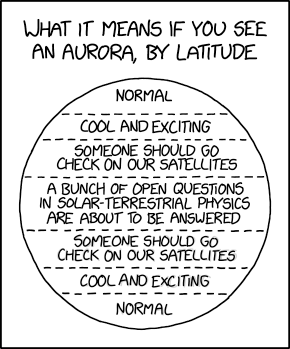
XKCD
Eastern VE3 is better than some and worse than others with regard to HF propagation. Many paths north of an east-west line traverse the auroral zone so that we are at the mercy of geomagnetic activity. At all times and especially during a solar cycle minimum stations a short distance east and south can enjoy remarkably better propagation on those northerly paths. By short I mean as little as a few hundred kilometers. Many the time I could only listen as many W1/2/3/VE1 stations work what I cannot hear or hear weakly.

This contest is no different. Many stations I am familiar with, including low power ones, could either put hundreds more European QSOs in their 20 meter logs or work many more zone and country multipliers. The difference is reduced when the sunspot count climbs and we are more competitive. This is with some decent antennas and heights. Some VE3 stations with better antenna farms do better than me but still not as well as their better located peers.

Skew propagation is well known on the low bands although I noticed little of it during the contest. Instead there was skew path on the high bands. This may be less well known yet it is common during marginal conditions. Europeans on 20 meters in our afternoon were peaking towards the east. This is usually ionospheric scatter from areas with a high enough MUF and not a true skew. A similar phenomenon occurs at sunrise when the rule is to "shoot the sun" on the high bands since that's where ionization is densest. There is also back scatter to nearby stations when we all beam to Europe, North America or elsewhere. This may be the only way to work them on the high bands when skip is long.

Unfortunately back and forward scatter is attenuated relative to a direct path. You need high power to have good results and even then you will likely only work the biggest stations. But it's better than not working them at all. Auroral zone scatter is also common on arctic paths. This was responsible for the strong Scandinavian signals and a BY in zone 23 that I worked on 20 meters deep in their night times.

Those with knowledge of these probable though not certain propagation phenomena can boost to their multiplier count. You can do it too by paying attention during your everyday DXing and using that experience during the contest.

Taking breaks and comfort

With high power there's always something to work no matter the band or time even when propagation is poor. If you can operate for the full 48 hours your score will show it. In the extreme some forgo food and drink to avoid the inevitable. For the humans among us it is necessary to take an occasional break. To keep your butt in the chair (BIC) you need every comfort you can manage. I am not that fanatical although I do pay attention to aids that keeps me in the chair.

One recent change was a new headset. After some consultation I purchased the Yamaha CM500. Although I was most interested in a robust cord I found them so comfortable that I could keep them on my head for long periods. This was not true of my previous headset the Koss 45 which would make my head ache after a few hours from the pressure against my glasses and skull.

I need a new operating chair. The old wooden office chair I've used for many years was comfortable when I was younger but no more. I need one with better ergonomics. Speaking of ergonomics I suggest paying close attention to the desktop. You need the table top (or your chair) to be at the optimum height to avoid fatigue from typing, sending CW and operating the rig. The less you have to swivel your head or chair to reach something the longer you can remain comfortable.

When you really need a break take it. Do not torture yourself. A few minutes walking around the house and talking to family members will refresh you. There is no need to take an official 30 minute break; just accept that you'll miss a few QSOs. Pour yourself a glass of water and head back to the shack.

I am fortunate that I can get by with little sleep. Each nights I only slept 2 hours, approximately from 4 to 6 AM (09Z to 11Z) when there is little to work after the low bands close to Europe and before the morning grey line opening. Speaking of sleep be sure you have an alarm clock that reliably wakes you up. Contests have been lost this way.

Wednesday, November 20, 2019

80 Meter Vertical Yagi: Completed

From first models to final design to final antenna took three years. It isn't that I was so slow than it was relatively low priority to putting up towers and other antennas. Construction began almost 2 years ago, then abandoned over the winter, and continued in earnest in 2018. When that was done I had a manually switched 3-element vertical yagi. For me that was an accomplishment, and I enjoyed the fruits of my labour over the winter.

What I didn't do last winter was to complete the array. The missing piece was the switching system. Its components include:
  • Switchable L-networks for the yagi and omni-directional modes
  • Tuned, parasitic element switching system: off-line; director; reflector
  • Switching matrix: diode array to select relays for the selected mode and direction
  • Control unit: manual switch in the shack to select mode and direction
All that work is now complete and the antenna is fully operational. Barring any repairs due to construction errors the antenna is complete. It works and it's a lot of fun to use. With this project out of the way I can concentrate on raising yagis, weather permitting.

In this article I'll step through the construction, testing and tuning. After reading this you'll likely wonder why I didn't build a 4-square with a commercial control system. Good question. For now I will only say that I enjoy designing and building antennas -- as should be evident from this blog. This antenna is an interesting and economical way to an 80 meter array with gain. I've made progress since the day it was little more than a giant pile of parts.

Parasitic element switch boxes

When I first tuned the parasitic elements and successfully rigged the antenna as a yagi I gathered sufficient data on the ground and on the air to ensure performance would be in accord with the design. Over the winter I gathered parts and refined the design of the switch boxes. Only then did I proceed to build the switch boxes.

The units are almost perfect clones. That is important to achieve near identical behaviour in all 4 directions. The coils were designed by software and a prototype was built. It was modified until it exhibited the exact required frequency shift -- from 3680 kHz (director) to 3450 kHz (reflector) -- when installed at the monopole base. With one working to my satisfaction I built the other 3 to the same specifications and confirmed that they behaved identically.


Box details are shown in the two above pictures. A few points about the design are worth mentioning:
  • Coil Q is not critical since the loss is low. Even at a kilowatt the estimated dissipation is less than 10 watts, and perhaps a little more due to dielectric heating of the PVC form. Insulated solid AWG 14 THHN wire is used. The insulation prevent winding shorts and ensures consistent winding pitch.
  • Wire routing and gauge is roughly identical to ensure all conduction path lengths are equal, and therefore frequency shifting is identical. AWG 18 wire is used for RF, which is easy to work with and more than sufficient in these short lengths to handle high power.
  • Stainless steel fasteners provide the studs for the monopole wire and radials. A solder lug is placed under the screw head inside the box.
  • The relays are sealed SPST-NO 12A in a PCB mount package. They are inexpensive when purchased in quantity. The pins are directly soldered, with the wire providing mechanical support. These relays are perfectly good when placed in a low impedance (hence low voltage) antenna point, just as they are in antenna switching products. When the element is floated the voltage across the contacts of the bottom relay is very low since the element is non-resonant. This was confirmed using EZNEC.
  • There is a hole in the bottom for the Cat5 cable and a pair more for the cable tie to hold it in place. These holes double as weep holes for moisture. The coloured wire pairs connect to a small terminal strip. If corrosion is a concern the screws can be coated with dielectric grease. Don't use silicone or other heavy duty gunk or you'll regret it when it comes to maintenance.
  • The boxes and coil forms are PVC. They are UV resistant and the box has a rubber gasket. The small 4" × 4" × 2" size is perfect for this application.
The boxes are mounted on a short length of scrap pressure-treated lumber which is turn is clamped to ~1 meter of rebar that is pounded into the ground inside the round PVC pipe that serves as the radial hub. You can study the physical construction in the picture below.

Holes are drilled into the wood to serve as a strain relief for the wire element. This is more reliable than wiring it directly to the box.

A length of wire beyond the connection point allows the element to be lengthened when more radials are added, which will raise the resonant frequency. The wire stub does not affect element resonance or performance if it's short with respect to wavelength; I tested this with up to 40 cm of wire stub with no problem. The end is pushed through another hole in the wood to keep it from coupling with the radials (and lawn mower blades).

Element tuning

While testing an element all the other elements, including the driven element, are floated; that is, disconnected from its radials and, in the case of the driven element, the transmission line.

A 9 volt battery powers the relays. Modern sealed relays with a 12 VDC coil reliably close with as little as 8 volts. The battery is small and portable, ideal for this testing in the field. Check the voltage periodically since it will wear out powering many relays.

Clip lead length does not affect tuning since DC common is isolated from antenna ground. The extra wire needed to insert the antenna analyzer between the radial hub and the box does matter. On 80 meters the frequency shift is ~10 kHz for every 6 cm of wire. The effect of the extra wire is therefore predictable and can be compensated for during tuning. For the best impedance measurements the analyzer should be connected on the radial side of the box.

All the coils were individually tested on one parasitic element to ensure they shifted resonance from 3680 kHz (director, with the coil shorted or out of circuit) to 3450 kHz (reflector). The same coil location and wiring topology in all boxes (see above) ensures identical behaviour of the elements.

With predictable coil performance all I had to do was adjust the monopole wire length to set the resonant frequency. The bottom relay connects the radials to the monopole through the coil to make the element a reflector, and floats the element when not energized. Energizing both relays -- ground the element and short the coil -- the element is a director.

The tarp provides a clean surface for tools, equipment and small parts. It further reduces the risk of ticks which are quite common here from May to July.

Tuning proceeded surprisingly well. All the elements achieved the 230 kHz resonance shift within measurement error. Using the 6 cm per 10 kHz rule mentioned earlier each element took only one or two adjustments. For example, to raise resonance from 3420 to 3450 kHz a knife is used to remove insulation 18 cm up the wire and then reconnected to the box.

The driven element resonated substantially lower than before due to the new longer stinger. Without a matching network the driven element has an SWR below 2 from 3.5 to 3.8 MHz. The resistance ranges from 29 Ω to 34 Ω and the resonant frequency (X = 0 Ω) is 3680 kHz. That this frequency is exactly that of a reflector element is purely coincidental is irrelevant to antenna behaviour.

Switching matrix

Direction is set from a control unit in the shack by placing +12 VDC on one wire and common. The control cable is Cat5 rated for UV and direct burial, in the same trench as the LDF4 Heliax transmission line. The power supply is 13.8 VDC which will be lower at the antenna. Voltage drop is due to the switching diodes, RF chokes and AWG 25 conductor resistance.

In some instances it may be helpful to draw up a voltage budget to ensure that switching systems work as expected. You can often get away with smaller gauge wire -- more economical -- than may be specified for commercial products.

Although I have yet to measure the voltage at the relays they are rated for full closure down to ~8 volts and there is no problem. Testing and tuning with a 9 volt battery in the field worked well, even as the battery aged and sagged down to 8.5 volts. 


The prototype board on which it is built is sitting on the circuit diagram. The 4 wires at the bottom are for direction selection: NE, SW, SE NW. Each side of the board is for a pair of opposite elements, with the 2 wires destined for the parasitic element switch boxes, one for grounding the element (make it active) and the other to short the reflector coil (make it a director). The other 2 elements are floated to be non-resonant and therefore inactive (no induced current).

The small components are 1N4148 switching diodes. The larger ones are RF chokes, one on each line to the shack and one on each line to the parasitic element switch boxes, so that all lines in and out, including the common, are choked; there are more chokes elsewhere.

The chokes reduce the risk of RF on the control lines which could affect the array and control software and EMI due to rectification of RF by the diodes. EMI protection is desirable on the shack end of the control lines although I do not have that as yet since there is no ill effect during use.

The diodes double as back EMF protectors when the relay coil voltage is interrupted. The common lines -- one to the shack and one to each parasitic element -- are also protected by RF chokes but are not on the PCB. The top diodes on the board select the L-network configuration. Antenna impedance is different for yagi and omni-directional modes. More about that in the next section.

The switching matrix is installed in a large PVC box installed at the base of the driven element. Content and wiring of the box is discussed below.

L-networks

Designing L-networks is easy using TLW (comes with the ARRL Antenna Book). All you need is the impedance of the antenna, which is best determined by measurement not the software model. As much as I and others heavily use computer modelling the impedance calculation for verticals and their radials over real ground with its variable composition, the model isn't sufficiently accurate.

Modern antenna analyzers come to the rescue. Use one of suitable quality and accuracy and the job of L-network design and tuning will be easier. My weapon of choice is the RigExpert AA54.


With the parasitic elements tuned and their switch boxes installed and operating the entire array can be configured from the control lines at the base of the driven element. Using a battery and clip leads I manually run through the parasitic element modes. When the array is unpowered it is in omni-directional mode and tuned for the CW end of the band.

Impedance was measured and recorded in 25 kHz steps from 3.5 to 3.65 MHz in all 4 yagi directions and every 50 kHz from 3.5 to 3.8 MHz in omni-directional mode. Recall that the yagi functionality is, at present, only available for the bottom 150 kHz of 80 meters. I wrote all R and X values on paper, which I find is more convenient than pulling the data from the analyzer onto a computer.

The impedance is not the same for all yagi directions despite the care taken in tuning and radial layout. There is a small amount of asymmetry due to construction and (very likely) lack of homogeneity within the mass of soil and rock across the 1 acre of land the antenna encompasses.

The reactance among the 4 directions is very close but the resistance at any one frequency varies a few ohms. That seems small but when the R component of the impedance is 15 Ω a difference of 2 or 3 Ω is proportionately large. It impacts the impedance curve among the 4 directions. In practice the SWR deviations aren't problematic (measurements further below).

With a full set of measurements in hand I played with TLW. My objective was a set of C and L values that would be convenient for switching among modes.


The basic L-network for the yagi modes is as calculated above. The impedance is an average among the 4 directions. The result is a low SWR across the CW segment and acceptable for the digital modes up to 3650 kHz. Yagi performance is degraded but still effective up to 3650 kHz.

As it happens I have a coil already wound, once I trim it down to size. Using K6STI's most recent Coil program my coil with 1" diameter and 6 turns per inch needs to be 1.9" long and will have a Q in line with TLW's estimate for loss. The coil is tapped approximately halfway along for an inductance of 0.75 μH which is needed to improve the SWR in omni-directional mode for SSB.

For the shunt C I use two 1200 pf capacitors in series to give 600 pf for omni-directional mode, one of which is shorted for yagi mode. Each capacitor is a vintage 1000 pf mica transmitting capacitor in parallel with 100 pf high voltage, low RF loss and zero temperature coefficient disk ceramic capacitors. Due to their relative values when in parallel the mica capacitor carries the bulk of the current, for which it is better suited.

The carefully engineered compromise of L-network components results in low SWR in all modes, including omni-directional SSB. Interestingly the SWR in omni-directional mode dropped to well below 2 without an L-network after I rebuilt the stinger. The reason is that the resonant frequency dropped to 3650 kHz due to its longer length. Of course the R value is low enough that impedance transformation remains worthwhile.

During final tuning I found that I could not achieve an SWR below 1.5 for the yagi modes. After making a few measurements and testing alternatives with TLW I added two 100 pf capacitors to the shunt capacitor (the other series capacitor is shorted in the yagi modes). Only one was needed to drop the SWR to 1 at the design frequency of 3550 kHz.

Frequency of minimum SWR differs among the yagi directions due to impedance differences among the elements. Since the SWR is between 1 and 1.2 at 3550 kHz it is inconsequential. The SWR at the edges of the design range -- 3.500 and 3.650 kHz -- is about the same since it is dominated by the large resistance and reactance change. This is typical of antenna matching networks.

The SWR curves are displayed further below. They were measured after the L-network adjustment complete.

A negative consequence of the L-networks is that the antenna no longer works on 30 meters. The topology acts as a low pass filter that has a high SWR above 80 meters. I chose the network topology to reduce inter-station interference during contests. The 80 meter inverted vee through the rig's ATU works well enough on 30 meters to be an interim solution.

Control box

I purchased a 6" × 6" × 4" PVC electrical box to house the switching matrix, L-networks and cable terminations. It sits at the base of the driven element (tower). External connections are for the coax, driven element RF connections, control cable to the shack and control cables to the parasitic elements.

The 5 Cat5 (8 conductor) cables pierce the wall of the box and are routed to the barrier style connector strips. On balance I deemed this approach better than connectors with respect to waterproofing, convenience, cost and labour. It requires some care in the layout to make it work well. The picture is of the completed box before being installed and the cables attached.


Yes, it does look messy! Despite that it works quite well. The relays are very lightweight and can be supported (suspended) by the solid connecting wires for RF. Control wires are separated from the RF section (bottom and lower left) to minimize interaction even though coupling with short wires at 3.5 MHz isn't a serious problem.

The control wires are made as long as necessary and RF wires are kept as short as possible. The photograph makes the depth look shorter than it is; there is more vertical separation than is apparent.

Layout detail:
  • Switch matrix is on the right wall. One screw with an insulated spacer supports it.
  • Connector strip for the control cable is on the bottom. Every terminal is labelled. The blank line carries +13.8 VDC to allow testing on site without need for a battery.
  • Labelled connector strips for the control lines to the 4 parasitic elements are at top centre. Chokes for the common lines and reverse EMF protective diodes for the 3 internal relays are between the strips.
  • Holes for the control cables (5 of them) are at the lower right. There are barely visible due to the camera angle. There are additional  holes for tie wraps to hold the cables in place.
  • There are 3 stainless studs at the bottom. From left to right they are for the driven element monopole, radials and 160 meters. Again, these are not easily seen due to the camera angle.
  • Coax connector (N) is at the lower centre of the left wall.
  • L-network series coil with taps for yagi and omni-directional modes. The relay just to its bottom right shorts the lower coil section for omni-directional SSB use.
  • The relay above it shorts one of the series L-network capacitors for yagi use. The capacitors are large transmitting mica with a few 100 pf 1 kV parallel high-Q ceramic capacitors. These are partially hidden by the coil and relay.
  • The DPDT relay at centre bottom directs output of the L-network to either the driven element or the 160 meter stud. The 160 meter option will be described in a future article after it is added to the antenna.
High value carbon composition resistors will be added later to drain precipitation static to the radials and ground from the driven element. It is a minor concern in our cold winter so it can wait for spring. The lightning protection system will be added at the same time.


The picture shows the completed box attached to the driven element and with all cables connected. Despite being even messier with the cables attached it was straight-forward to wire and test. The bracket that holds the box to the tower needs to be replaced with a piece of lumber for improved mechanical support.

Colour coding is standardized with colours written on labels inside the box and documented in my files. Make sure you do this since you won't remember (trust me on this). There are 24 control lines: 8 to the shack and 4 to each parasitic element. After considering options I opted to install short cables to the internal terminal strips, which could be down indoors in comfort. Crimps on the outside of the box to attach them to the 5 cables.

It took a couple of hours in the field to get it all connected, tested and temporarily weatherproofed. For maintenance that requires box removal it is inexpensive and quick to simply cut the lines and reattach them later. I will use connectors for the external connections if maintenance and antenna improvements occur more often than currently anticipated.

Impedance tuning of the antenna

The antenna has 7 operating modes: 2 omni-directional modes optimized for CW and SSB band segments; 4 yagi directions; and 160 meters. The last is not yet implemented. That leaves 6 modes to be matched to the 50 Ω transmission line.


With the L-network installed the initial tuning could proceed. First to be done were the CW and SSB omni-directional modes. These did not require manipulating the control lines to the parasitic element, which were left disconnected and not yet routed into the control box. As before a 9 volt battery was used. The taps for the full coil (CW) and SSB were adjusted until the SWR curves were optimized.

The coil is at least 50% longer than needed. It was pulled out of my junk box and I didn't bother shortening it to give me more tuning room should I ever need it. The coil values calculated with TLW are approximately 1.5 μH for CW and 0.75 μH for SSB. Based on the coil dimensions the taps ended up not far from these values.

The shunt capacitor should be approximately 725 pf for CW and 500 pf for SSB. Instead I fixed it at about 600 pf for both band segments; that is, with the two 1200 pf capacitors in series. One of them is shorted for yagi modes since its shunt capacitor is calculated to be in the range 1150 pf to 1300 pf. The range is due to the impedance differences among the 4 directions as previously noted.

The component choice allows for a minimum of alterations (by relay) among modes. The design was intentional in this regard to keep the switching as simple as feasible. This is an interesting topic on its own which I may cover in a future article.


The SWR curves for the omni-directional modes are very good. They cannot both be perfect since it is only the value of the series inductor that changes, not the shunt capacitor. Adjusting the capacitor value would help little since although it would bring the minimum SWR to 1 the tails of the SWR curve would be about the same. This is typical since as you move away from the centre frequency the R and X departures from the ideal dominate the impedance.

With that done I connected the battery to the parasitic element control lines to adjust the L-network for the yagi modes. There is variation among the 4 directions due to the aforementioned parasitic element impedance differences. Rather than show all of them here is just the one for northeast. The others are similar or better.


Per the design the SWR soars at the 3650 kHz upper end of the design range. This is unimportant since the gain and directivity decline rapidly above 3625 kHz.

With the L-network adjustment complete the box was brought indoors to solder the coil taps and install the parasitic element cable harness (see below). After reinstalling the box there was a problem. A clip lead to the radial hub was used during L-network adjustment. When I replaced this with a permanent wire the SWR for all modes increased since it was shorter. It was far earsier to increase the wire length than adjust the networks. Wire length matters.

The SWR plots were done in the shack not at the antenna. Out in the field I forgot to save the analyzer plots and I didn't want to brave the cold and redo the weatherproofing just for this article. The SWR curves are more nominal at the other end of the 300' transmission line. The difference is probably due to a deviation from 50 Ω in a section of old RG213. Attenuation is very low at 3.5 MHz and thus contributes less to the impedance difference at the shack end of the transmission line.

Component choices

There are not many types of components in the switching system and networks. Judicious choices are necessary to ensure proper operation and reliability. Some of what I needed comes from my extensive junk box. Other components were purchased. The price is low when you buy in bulk from the major electronic component outlets. Most of these were purchased from Mouser and there are many other sources with good reputations and prices that also make it easy to do business with them in Canada.


  • The 1N4148 switching diode is used throughout the switching matrix. They are cheap, small and effective. They double as back EMF protection for the relays they power. While not ideal in this latter application I was willing to take the easy route. Others use them in similar antenna systems with good results.
  • For relays not powered by the switching matrix I used 1N4007 rectifier diodes for back EMF protection. They are more robust than the 1N4148 and indeed are overkill with their 1 kV reverse voltage rating. I had them on hand so I used them.
  • Old 1000 pf mica transmitting capacitors in combination with parallel 100 pf disc ceramic capacitors make up the two 1200 pf series capacitors in the L-network. These are stable and can handle a kilowatt of power. The 100 pf capacitors are 1 kV, low temperature coefficient and the ceramic material is low loss at RF. They each carry about 10% of the antenna current since they are in parallel with 1000 pf mica capacitors.
  • The RF chokes (lower right) are rated for 600 ma and are resonant at 6 MHz. The current capacity is well above the draw of the one to three relay coils they each support. The series resistance of ~1.5 Ω has negligible voltage drop in my control system. It is important that the self-resonance of the chokes be outside of amateur bands to ensure they perform properly.
  • The TE Systems 12A SPST-NO relays do the bulk of the switching chores in the L-network and parasitic element switch boxes. Both sides of the Omron G2RL DPDT relay switch between 80 and 160 meters at the output of the L-network to double the contact rating. All the relays are small, sealed and reliable up to a kilowatt. This type of relay should only be used for low impedance switching since with high impedance the RF voltage is too high. For those applications use vacuum relays or relays with a large contact gap.
  • PVC pipe as a coil form is acceptable at 80 meters but not for QRO above 20 meters or so. Loss (heat) in most PVC formulations rises with frequency and becomes a problem. I use PVC forms and insulated (THHN) wire in the parasitic element coils to achieve dimensional uniformity. The L-network has an air core bare wire coil from my junk box. Bare wire is handy for tapping the coil to adjust the impedance match.
  • Internal RF wiring in the 5 boxes is AWG 14 and 18. Smaller 18 gauge wire is acceptable despite the high RF currents since the lengths are short and ohmic loss is negligible. The dead bug construction method favours small gauge wire connections to the relays.
Control unit

The cutouts for the 80 meter array were included in the manual antenna control unit when it was built. A 6-position rotary switch and toggle switch do all that is required in the present antenna configuration. The only design question is which direction and mode to assign to each position.

When unpowered the antenna is in omni-directional mode with SWR optimized for CW (see L-network discussion above). For switching convenience I placed the CW omni-directional mode between the 160 and yagi position. Since the most common yagi directions are northeast (Europe) and southwest (bulk of the continental US) they are the adjacent positions. The less common directions are in the furthest clockwise positions: southeast (southeast US, Caribbean and South America) and northwest (Japan, east Asia).


During CW contests antenna mode and direction requires one one click most of the time. This is usually between northeast and southwest, with occasional forays to southeast, and rarely to northwest except grey line openings to Asia.

For SSB contests there are only two choices, both omni-directional modes with SWR optimized over different band segments. Most often the SSB switch is the only one needed; set once and forget unless you want to "rest" the L-network relay when 80 meters isn't in use.

As currently configured the SSB switch position disables the rotary switch. This works since the only SSB mode is omni-directional. Should I add SSB to the yagi modes the wiring must change so that the mode selection would select (short) coils in the 4 parasitic elements to move the centre frequency from 3550 kHz to 3700 kHz or thereabouts.

A wiring error among all the cable harnesses reversed the SE and NW directions. I'll have to track this down. I could reverse the wires in the control unit except that would violate my Cat5 colour coding and invite future confusion. There is no rush and there is no great consequence during use. Apart from this one error the control unit works perfectly.

Grounding

With the driven element, parasites, radials and control system isolated from physical ground there are a few challenges implementing lightning protection. Although this region has a lower risk of lightning strikes than many other protection is still required. After all, an 80 meter full size vertical sitting in the middle of a hay field can be a very attractive place for a lightning channel to form.

There are two problems to be addressed: lightning strikes and precipitation static. For a direct or secondary strike I want an easy path to ground for the lightning current despite the antenna's isolation from ground in normal operation. The electronics are unlikely to survive and are easy to replace, but I do want little of the strike current reaching the shack ~100 meters distant. Precipitation static needs to be continuously bled to ground to avoid excess receiver noise when it rains or snows.

For both problems ground rods are needed. To drain static it is enough to place a high value resistor between the antenna elements (including the radials) and ground rods. The typical method to deal with direct and secondary lightning strikes is with two copper balls separated by a spark gap, one on the driven element and one on the ground rod.

I hope to implement both solutions next spring before summer storms arrive.

Performance

Does it work? The short answer is yes. There is close agreement between what the computer model predict and how it performs on the air.

This is not a "perfect" antenna and it was not designed to be. Its performance pros and cons are quite interesting. This article is already long enough and I would like more experience using it before writing it up for the blog. Perhaps in December, after CQ WW CW and when the weather forces an end to tower and antenna projects this year and I spend more time indoors.

Summing up

For someone who enjoys playing with antennas this has been a fascinating project. I've learned a great deal and I've gained an effective directional antenna on 80 meters. I will continue to monitor its performance over the winter in contests and daily DX chasing. The future of the antenna will then be decided.

I definitely plan to add 160 meters to it, per the design and construction. It won't be difficult and will be an interesting project. I may in time want to add SSB to the yagi modes, something that isn't possible now due to the narrow bandwidth (less than 150 kHz) of the yagi. It will require changes to the parasitic elements and control architecture; the control lines are already installed.

What is particularly interesting is how the yagi's performance compares to the popular 4-square that is used in many big gun stations. The major differences I knew before starting this antenna project. Now I'd like to make the comparison quantitative, for my benefit and for readers. It will be enlightening.

Thursday, November 14, 2019

Abrupt Change of Season

The best laid plans are no match for Mother Nature. November has been less than kind in this part of the world. November began cold and windy, then came the snow. So far we've had 25 cm of snowfall. It isn't melting. Temperatures have gone as low as -17 C with wind chills even lower. Records have fallen. One wind storm brought gusts well above 100 kph that had the house shaking. After the sun rose I saw that all the towers and antennas survived.

Some moderation is in the forecast though not what it should be. Normal highs in early November range from 8 C to 6 C. This is comfortable for antenna and tower work. My plans relied on weather that did not vary too far from the expected. Now I'm faced with this:


In the foreground is one of my new 20 meter long boom yagis. In the background is one of the 15 meter yagis. A second 15 meter yagi is buried in the snow and can't be seen. These are 3 of the 4 big yagis for my 15 and 20 meter stacks for the newly completed 140' (40 meter) high tower in the background.

The frustrating thing is that the antennas work. They've been tuned and tested. All that's needed is the permanent gamma match assemblies, mounting hardware and boom trusses. Despite progress of all of those it is unlikely that these antenna will be raised in time for CQ WW CW which is rapidly approaching.

However it is not all bleak. With a moderation in the weather (likely) the side mount yagis will be completed and raised. The tower brackets are ready to go and the tram line is in position. Most of the truss hardware is ready to be assembled. Heliax feed lines are in the midst of assembly and testing. All of it looks good.

With these pointed at Europe I will have more capability in upcoming contests. If I get lucky the mast can be raised and the rotatable yagis can be lifted onto the mast. These operations require less snow on the ground to allow a power lift: they're too heavy to be trammed by muscle alone.

My 40 meter rotatable dipole project is similarly on hold. In fact I have not assembled it although all the material is on hand. This is an impediment for chasing distant multipliers on 40 meters since I moved the XM240 from its previous 46 meter height down to 21 meters. On the positive side this antenna should not be too difficult to raise. All that will be needed is to build and tune the gamma match. The transmission line and rotation loop are ready for use.

For now I do what I can on the ground and hope for better weather. Failing that I am forced to wait until spring. Around here that means at least 5 months (April) and possibly May. June through mid-August is haying season when little work on the big towers is possible.

Saturday, November 9, 2019

Thoughts on Two Keyboard SO2R

In the ARRL Sweepstakes CW contest last weekend I operated SO2R using two keyboards. This was a first for me. Several months ago I purchased a wireless keyboard and mouse so I had the keyboards ready to go.

SO2R (single operator, two radios) is used by skilled contesters to maximize their score. This comes at the expense of mental fatigue and a difficult learning curve. It is possible to practice offline with running simulators such as Morserunner, yet that is no substitute for reality, especially if you have a small station and need to S & P (search and pounce) quite a bit.

Among SO2R aficionados there are those who use one keyboard and those who use two. Both can work well, and you'll find a mix of techniques among the top contesters. The differences are many yet, I believe, can be roughly compared as follows:
  • One keyboard: Less physically fatiguing since you hover over just the one keyboard. It can be more mentally fatiguing since you rely on special keys to change radio focus, carefully monitor the display to confirm radio and QSO state, enter what you hear in the correct radio window, deal with out-of-pattern situations such as requesting or responding to fills, etc. Once you become skilled the mental fatigue declines.
  • Two keyboards: More physically fatiguing since you literally constantly switch between keyboards for each QSO state. Fatigue can be reduced with software features to direct commands from a keyboard to the other radio, automatic CQ, etc. With practice there is an improved economy of motion that reduces physical fatigue. Mental fatigue is lower since focus in determined by keyboard use without the needs to use and monitor radio and QSO state.
Now that I've done it I've gained an appreciation of two keyboard SO2R. My software of choice is N1MM Logger+. Some of the other popular contest loggers also support two keyboards. Because my experience is limited to N1MM my discussion of its pros and cons may not be entirely application to other contest loggers. Some of the quirks that I encountered using N1MM two keyboard SO2R may be bugs -- yet to be confirmed -- so I won't dwell on them here.

Operating desk

My operating desk for Sweepstakes was as shown below. The photo was manipulated to reduce the screen brightness, which unfortunately does not help much! Those familiar with N1MM should recognize the two entry windows at the centre bottom and their respective band maps at either side. The other windows I have open are not pertinent to SO2R.


When I use one keyboard it is in front of the display. The paddles and mouse would be on the right of the keyboard since I'm right handed. With two keyboards placing them between the keyboards worked the same for the left radio and required a bit of arm crossing when on the right radio. My manual headphone switch is behind the paddles. The manual antenna switch is on top of the right radio.

Compare this with a photo of my single keyboard setup and an explanation of my home brew headphone switch. Many operators using one keyboard, SO2R or not, persist in putting it in front of the radio and the display up above. Disadvantages include arms and hands dragging on the keyboard when operating the rig and constantly having to tilt the head up to look at the display. I keep the display low so that my head and neck stay relaxed and keep my reach to rig control unencumbered.

You have to touch the rig less than you might imagine. The exception is small stations since you must spin the VFO for S & P. With N1MM and other contest loggers there are a host of keyboard shortcuts for many rig features that, as you learn them, require far less manual control of the rigs.

Those with rigs with full software interfaces (e.g. Flex) and advanced station automation have no boxes and physical controls to deal with; the operator uses the keyboard or mouse. The typical setup for those stations is to place two or monitors side by side. For SO2R with two of these rigs there would be two PCs and therefore two keyboards. SDR rigs with two slices can share one PC and one keyboard.

Which is better for the SO2R novice?

As already mentioned, many of the top contesters continue to do SO2R with one keyboard and suffer no deficit in their results. For the experienced contester who is a novice at SO2R the choice can make a significant difference. Having tried both my tentative conclusion is that two keyboards is the better choice for the SO2R novice.

The major challenge with single keyboard SO2R is the steep learning curve. There are many balls to juggle and quite a few mistakes will be made. Although the software will usually put the typed call and exchange in the correct window each radio's QSO state and software focus must be constantly monitors and keys pressed to change focus as needed. Alternatively you can explicitly send commands to the opposite radio. Keeping it all straight takes practice, a lot of practice.

With two keyboards you can get started and be quite productive with far fewer critical operations to remember and use. Rather than change focus or direct commands you simply manipulate the keyboard associated with the desired radio. This comes at the cost of swivelling more in your chair and its attendant latency.

Another aid for novices is to use low power or even QRP as I did during Sweepstakes. The lower rate and lower value of dual CQing keeps the stress to a minimum. There will be fewer moments of intense activity. Another suggestion is to try SO2R in small and regional contests (e.g. QSO parties) where the activity level is lower or intermittent. By keeping the stress low while you learn you'll have more fun as you hone your skills.

Once you get the basics mastered you still have access to and can use keyboard controls to direct commands to the other radio. For example, to repeat an exchange on the other radio you can direct a command (CTRL-F2 in this case using N1MM) from the same keyboard you are entering info you are copying on the other radio. By cutting out some of the swivelling you reduce fatigue as your skills improve.

In time you may opt to switch to single keyboard SO2R. Choose which works for you. My suggestion is to try both rather than assume that one or the other is better. Keyboards are cheap and you probably have a spare collecting dust.

Go with wireless keyboards to reduce demand for limited USB ports (hubs don't always work well) and fewer opportunities for RF to get into the PC and cause glitches.

Plans going forward

I plan to replace the operating desk to be more contest friendly. It has to be longer to accommodate two operator positions (multi-op contesting), no drawers to bang knees into and reduce operator reach and have multiple levels to keep ancillary equipment within easy reach. As automation is deployed there will be less need for ancillary equipment, such as manual antenna switches, or the functions will be moved to software (PC control of rotators, antenna choice, etc.).

Because the keyboards make it more difficult to control buttons and dials a popular solution is to raise the rigs on a low shelf. There is less risk of accidental key presses when reaching for the rig. In some designs the keyboard can slip underneath the rig when not in use. Desk clutter is reduced when the station isn't being use.

Another shelf above the rig can support manually tuned amplifiers to keep them in easy reach to tune them after band changes, and for frequency and antenna changes within the same band.

Since the layout for two keyboard SO2R is similar to that for two operator multi-ops there is less work to do before and after the contest. Rotate a few boxes, roll up another chair and you're pretty well ready. The need for a second PC and display(s) will initially increase the complexity of transitions until the process becomes routine. The greater the degree of automation the fewer the items that must be rearranged.

Over the winter my shack plans will be refined. I'm not sure how much I'll actually do this winter except that I do want to be multi-op ready so that I can invite my friends over for contests. An effective SO2R station is a step along that path.

I consider myself an SO2R novice and I will keep practicing in contests and evaluating alternative station configurations.

Tuesday, November 5, 2019

QRP for the FTdx5000

After selling my Elecraft KX3 earlier this year (as planned) I was left with one rig that could be dialled down to 5 watts for entering contests in the QRP category. That rig is a Yaesu FT950, a rig with very dated technology. It used to me my main transceiver for most operating. Although I still enjoyed using the KX3 its use was solely for QRP contest entry after returning to using higher power.

Because its receiver is quite poor I avoid the FT950 other than as a second radio for SO2R contest operation. Until I upgrade shack equipment to be more contest friendly I use it to practice SO2R. Eventually it'll be replaced.

My main rig is an FTdx5000. This 200 watt transceiver cannot be reduced to QRP power level. Its minimum setting is 10 watts. The problem was that I intended to enter the ARRL CW Sweepstakes contest in the QRP category this past weekend. I couldn't bear the thought of using the FT950 all weekend.

I also wanted to improve my modest SO2R skills. This contest is great for that since the pace is more measured and with QRP I don't have high hourly rates beyond the first few hours. I also wanted to improve on last year's score when I might have won had I operated full 24 hours.

My objectives meant borrowing a transceiver or fitting the FTdx5000 into a QRP box. I opted for the latter. Aside from what ought to be the obvious solution that I eventually selected a few other paths were investigated:
  • Class A: Running the transmitter in low distortion and low efficiency class A reduces the maximum power to 75 watts. It turns out that adjusting the power does not proportionately decrease the power by ⅝ at all level. If you set the power to 10 watts you still get 10 watts, but a supposedly very clean 10 watts.
  • External ALC: There is a negative feedback port on the rear panel to allow an external amplifier to dynamically reduce the power level when it is over-driven. I tried it with a AAA battery in reverse polarity -- the port accepts from 0 to -4 volts. Nothing happened. An internet search didn't solve the puzzle. E-ALC was ruled out since time was running out.
  • Lossy coax: Unfortunately I had none suitable that I could connect. In any case the loss would be frequency sensitive.
Not surprisingly I went for the brute force solution: an RF attenuator. It's a simple project that took me only two hours to whip up in the workshop. It has just a few design parameters:
  • Knock 10 watts down to 5 watts from 1.8 to 30 MHz.
  • Dissipate 5 watts of heat, preferably with 100% duty cycle for ultimate robustness.
  • Good impedance match to 50 Ω.
The circuit diagram for 3 db attenuators with 50 Ω ports is easy to find. Calculation is more difficult. From an old ARRL Handbook the series resistance is 18 Ω and the parallel resistance on each port is 300 Ω. These are exact or close to standard resistor values so I went digging in my junk box for suitable candidates. Then it was off to my workshop.


Before visiting the junk box I did some calculation to determine that most of the power dissipation is in the parallel 18 Ω resistance. This isn't surprising since it is by far the lowest resistance in the network, ports included. I didn't bother figuring out the exact dissipation values since close is good enough for this application and solving resistor networks isn't fun.

Construction is incredibly simple. The biggest job was punching the ⅝" holes for the SO239 panel jacks. I used the cheapest jacks I had on hand. The box is new from my stock of plastic and aluminum boxes that I keep on hand for home brew projects.

Although simple there are a few points worth mentioning:
  • The box should be conductive to prevent RF leakage in and out and to minimize frequency sensitive impedance variation.
  • The wire between the jack shells further improves high frequency performance. It's better than solely relying on the enclosure. Notice the short leads of the parallel resistors the wire makes possible.
  • Carbon composition is the best choice with carbon film close behind. For HF use other resistor types can be used but never use wire-wound resistors.
  • Resistance values can be achieved with multiple resistors in series or parallel. With the help of an ohmmeter you can get very close to the exact values. Resistors often deviate from the specified value (pay attention the tolerance colour band) so try them all. Multiple small size resistors can have the power dissipation rating of a single high power resistor which is less likely to be found in the junk box.
After soldering it together I plugged my antenna analyzer into one port and a 50 Ω load into the other and swept the HF spectrum. It's very flat with a maximum SWR below 1.1 up to 30 MHz. I didn't test it at 6 meters and above.

The final test was to connect it to the rig and place watt meters at each port. Since I have only one standalone power meter I relied on the rig's PO meter for the transmitter port. Power was reduced to 10 watts and tested at a few frequencies.


The result was very good. Since power meters are often inaccurate I compared the meter reading with what I recall from using my KX3 at 5 watts. Both readings are a whisker above the 5 watt tick. The difference expressed in decibels would be exceptionally small. In any case the true output of any transmitter is never as precise as suggested by the digital display.

As a further test I opened the box and ran the transmitter with a solid 10 watt carrier for a few minutes. There was no smoke coming from the resistors nor was there obvious heat radiating from them. The series resistor pair was a little warm.

There are a few items to keep in mind when operating with an attenuator of this type:
  • If your rig has a physical power level control it is easy to forget the attenuator is there after you're done with a QRP event. Transmit at 200 watts and you'll have to replace all the ruined resistors. Look for the software parameter to limit the maximum power to the lowest setting. On the FTdx5000 that is 20 watts. The attenuator will survive dissipating 10 watts.
  • Receive strength is reduced by 3 db. On HF you may not notice, more so during the present solar minimum when you are not often on 10 or 15 meters. If it's a problem increase the rig's pre-amp setting. Modern receivers have an abundance of pre-amplification features.
  • You don't need a tuner! The increased return loss due to the attenuator greatly lowers the mismatch seen by the rig. For example, my poorly adjusted 80 meter inverted vee has an SWR of close to 3 at 3500 kHz and requires the ATU. With the attenuator the SWR was not much worse than 1.2 so the ATU was switched off throughout the contest. 
  • Despite the low SWR seen by the transmitter the SWR at the antenna port is unchanged. Large deviations from 50 + j0 Ω will change the attenuation level to a value lower or higher than 3 db. For high SWR you should use a tuner between the antenna and attenuator to be certain that you are below the QRP power limit.
The attenuator worked perfectly during Sweepstakes. I was going to discard it afterwards (recycle the components) then reconsidered since there are other contests in which I'd like to have the option of operating QRP. One possibility is the Stew Perry TBDC on 160 meters this winter. I'll keep it around.