Monday, September 30, 2019

One Step Forward

My one step back a few weeks ago continued to the point where I had just one HF antenna: the 80 meter vertical. This kept me off the air and focussed on rebuilding. The removal of almost every antenna was necessary to move and repair antennas in preparation for the next configuration of my antenna farm. It has been a very busy time.

With the help of friends I am again active on all bands from 80 through 10 meters. Until more antennas go up my flexibility is limited, so I cannot call this progress. That explains the title of the article. Over the next month there should be enough progress that I can truly claim that I have taken one step back and then two step forward.

For now it's just one step forward in which the station is different but at similar capability to what it was a month ago. In this article I'll run through the progress so far.

TH7: high tri-band yagi

I will have little to show for 10 meter antennas when this year's work is done. That is acceptable for the next year since signs of life on that band will remain elusive for at least that long. With a large tri-bander up at 43 meters this will give me flexibility during contests to target, say, South America at the same time as Asia on 20 meters. I am assuming my new 20 meter and 15 meter stacks on the new tower will be ready and I am working hard to make it so.


I really like this picture. The Hy-Gain TH7 dangles at the bottom of the tram line fully rigged and ready to be hauled over the hay field to the top of the big tower. Posing with the antenna is my trusty ground crew (left to right) John VE3NJ, Don VE3DQN and new ham Alan VE3KAE.

Notice how the antenna is well balanced so that the boom is level and the elements point straight ahead. This is the correct orientation to clear the guys and not strike the tower or mast. Those element tips are fragile. Two people lifted the boom as the tram line was pulled tight to prevent the elements from catching on the ground. Two people manually operated the haul rope during the lift. Power makes the job easier but increases risk of damage when the the antenna strikes an obstacle.

Many hams attach yagis to tram lines with custom made rigs that guarantee good orientation. I do it old style with ropes. With practice ropes work very well and allow for rapid removal and easy packing at the top of the tower, an important consideration. In this instance it worked beautifully as the close spaced driven elements of the TH7 slid right around the tower and mast.

One mistake I made was to point the antenna backwards. Although this is easy to correct by calibrating the prop pitch rotator controller the direction I dressed the cables and rotation loops is not compatible with a north centred rotation, which is the preferred method in this part of the world. I avoided rotation until it was fixed a few days later.

The TH7 was retuned to resonate lower in the band. SWR is a little higher than ideal at the low ends of 15 and 10 meter. but better than it was before. The boom is attached to the 3" mast using the same modification I used for the TH6. I shortened the DX Engineering saddle clamp on the top side to avoid it contacting the phasing line between the driven elements.

Other tri-band yagis

The reason the TH7 is up there and not the TH6 is because the close spacing of the driven elements does not easily permit tower side mounting. The TH6 is better for this. It was trammed to 75' and pointed roughly south to permit working Caribbean and Central American multipliers and the southern US, all of which are present during opening to Europe on the high bands. It uses the same side mount bracket as used previously for the Explorer 14.

The Explorer 14 is now gone to its new home where it will soon bring home the DX to its new owner. Although a small antenna it did well for me during the past several years.

The TH6 was inspected after removal from the tower. A couple of 
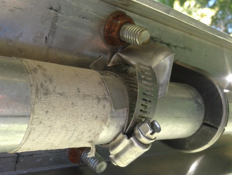
defects were discovered which I assume these were responsible for problems that began last winter. The worst was the poor design of the driven element clamps that connect wires to the balun and beta match line.

The tabs on the aluminum wraparound clamp bend when the bolt is tightened. There is no provision in the TH6 to prevent this so the wire studs don't sit flush against the tabs: they wobble. My antenna was particularly bad due to its great age.

I added two backing nuts to allow fine adjustment of the clamp pressure and squarely bond stud and tab. The TH7 is better than the TH6 in that it has one backing nut, but still not the two I used. The studs were weatherproofed after taking the picture since the tinning has deteriorated. The hardware is stainless.

I took the opportunity to move the yagi's optimum performance higher on each band. Previously it was set for CW so the SWR was poor at the upper ends of the SSB band segments. Not wanting to lose CW performance I opted to shift it slightly higher, just below the settings for "Lo Phone". Because there is only so much bandwidth possible with a tri-band trap yagi some compromise is necessary. Eventually the TH7 will be converted to a TH6 so the two can be stacked for added performance. The conversion is necessary to achieve a similar impedance and therefore good power division.

I made a mistake with the tram which at least doubled the time to raise it to its new home. The upper tram anchor and haul rope pulley were too close to the mounting position. Manoeuvering a big yagi in a stiff breeze with ropes getting in the way and pulling the antenna out of my hands was too much. We lowered the antenna and redid it properly. Expedience costs rather than saves time.

XM240 40 meter yagi

This small 40 meter 2-element yagi has been returned to its original location on top of the Trylon tower at a height of 21 meters. The lift went pretty well considering the necessity of dropping several above grade cable runs and navigating the long elements around the trees that have grown over the previous two summers.

A few modifications were made to improve the antenna. The previous owner modified the antenna to make it more robust in extreme weather. He did a fine job of it but he should have chosen better hardware when he replaced the Cushcraft element-to-boom clamps. The cheap galvanized muffler clamps do not have enough grip to prevent the elements from rotating.

I inserted galvanized mesh under the clamps to provide mechanical texture to improves the grip. While not ideal I could not simply use better clamps such as the flattened and textured DX Engineering Cycle 24 clamp since there is no reliable sizing of muffler clamps and I'd have to drill more holes in the aluminum channel. Too many holes risks weakening it. Time will tell how this improvisation deals with the wind.

The other improvement was to ground the reflector element to the boom. This is a popular mod to reduce precipitation static by providing a path to ground for the static charge. Performance is not affected. Precipitation static was a serious problem at 150'. We've had one rainfall since the antenna went back up and...there was precipitation static, though not as bad as in the past. I'll continue to monitor.

I adjusted the rigging to ease attachment to the mast. Ideally two on the tower eases installation of this unwieldy yagi but I made do on my own by adjust the rigging and the procedure. The lift was done the same day as the TH7 with the same ground crew. I spent two days beforehand to prepare the antennas and rigging on both towers to best utilize the time of my friends.

In the picture I am in the process of attaching the mast clamps. There are a few interesting features of the rigging that are worth mentioning:
  • I attached the boom truss to the lift rope. This kept it out of the way during the lift, made it easy to slip onto the mast and by keeping it in one piece there is no risk of one end slipping out of reach while it is being assembled on the tower.
  • Long ropes are looped over each side of the boom. These tag lines allow fine control of antenna orientation in tight spaces. When done pull one end of the rope and it falls to the ground.
  • Precise positioning of the mast clamp needed to insert the clamps for an antenna this size is no easy task for one person. I used a couple of cargo straps as a third hand. I previously slipped all 4 clamps onto the mast and raised them one by one, top to bottom, for attachment. The rigging must keep the plate flush to the mast since there is nothing on the boom to grab onto to rotate it.
There are a few reasons for placing the XM240 at this new location. First, I need a directional yagi at intermediate height for contest work. Although side mounting it on the big tower is possible I do not have time this year to build a side mount suitable for almost full 360° rotation. Second, the Trylon is close to the house and there are many weak noise sources that are audible on 20 meters and above where the atmospheric noise level is low. This is not a problem on 40 meters. For long paths I have another plan for this autumn: a full size rotatable dipole above the TH7 on the big tower.

80 meter inverted vee

The 40/80 meter inverted vee that was on the Trylon is headed to its new (old) home on the 150' tower. However the 40 meter element of the fan dipole has been removed so that it's solely for 80 meters. It is no longer needed on 40 meters and it used to twist and tangle in the wind which would make it unusable on 40.


The tower mount has been improved from an ABS pipe to a steel angle bracket. The new bracket is far stronger and will take more tension. It is also a better mount for the balun (common mode choke). Strain relief for the wire legs keep stress away from the balun studs.

Modelling tells me the best pattern for short paths and low directivity is at a height at or a little above 30 meters. This will  also keep it well away from the other antennas on the tower. Unlike its original installation the two legs will go down into the tree line on the north end of the hay field, avoid ground anchors in the hay field. The model shows almost no effect on the pattern by doing this.

It should be a good antenna for the QSO rich northeast, mid-west and south-central US. After sunrise and before sunset a horizontal antenna often works better than a vertical on 80 meters on both short and DX paths. Unfortunately it's resonant frequency is ~3700 kHz, ideal for neither CW nor SSB. If widening the legs of the vee more doesn't help I'll lengthen it to lower the SWR below 2 within the range of 3500 to 3600 kHz. My primary use for the antenna is CW contests and DXing.

One step forward

Other antennas

With the bulk of the tramming on the 150' tower is done I deployed the radials for the 160 meter antenna and connected the over-ground coax. I kept the field free of trip hazards for the safety of the crew. The match is different each year I deploy this antenna. This year it resonated at 1800 kHz so I adjusted it to resonate at 1825 kHz. I believe the variability is due to the distance from the antenna from guy wires and the directions the radials run, neither of which are identical each year.

Work on the 80 meter vertical yagi is delayed. Since this antenna can be done by myself on the ground in the cold weather it is low priority. It's just a little frustrating that this project is taking two years to reach fruition. However I budget the time and energy I devote to amateur radio so that it doesn't become a burden. On the positive side it really is almost complete.

The last stage of aluminum work on the 20 and 15 meter long boom yagis is done. I have only to cut and insert the element tips, mount them on the boom, build gamma matches and raise them for tuning. October will be a busy month.

The mast bearing plates for the new 140' tower were assembled and declared unfit for use. I made an error in the template that requires modification in my workshop. This is a temporary obstacle. I expect to raise the top sections of the tower along with the mast and prop pitch motor by mid October.

When everything is completed I will be ready for the winter contest and DX season. Next year will be less busy with only a few large projects. More on those in the coming months. Right now I remain focussed on antenna building and becoming reacquainted with the HF bands since I did little over the summer other than 6 meter DXing.

Saturday, September 21, 2019

Relative Strength

Any ham with a tower or who has home brewed yagis will know there are a variety of software tools available to help with mechanical design. There are mast stress calculators to determine wind and ice survival of various grades and sizes of steel masts. Other calculators will determine stress on yagi booms and elements with attention to wind and ice loads. For the experts there are FEA (finite element analysis) engineering packages that handle most complex structures such as towers, both guyed and free standing.

Most of these tools are not used when buying commercial products. Instead we rely on manufacturer specifications and recommendations. Unfortunately some knowledge of various standards may be required since many advertisements attempt to place products in the best light and therefore choose to highlight specifications that may mislead even when accurate. Buying is not always worry free.

Guessing, optimism and hope abound among hams, including myself. I often calculate but other times times I rely on extrapolation from known designs and existing installations. If done carefully it can produce good results.

This is not an article about all those software and web tools for doing the heavy lifting for those mechanical calculations. Instead I want to discuss how I resolved a common question I deal with all the time when doing these calculations:
What happens when I change X?
X is a variable regarding a pipe or tube choice that may include but not limited to:
  • Strength: bending, axial or other load limit
  • Weight
  • Wind load
  • Cost
All have a bearing on the choice of boom, mast and yagi element structural members. It is helpful to play the game of What if? to see if the change is helpful or deleterious with respect to those criteria. Sometimes I choose pipes based on what best fits!

The relationship among those values can be complicated since, for example, reducing pipe diameter reduces strength and weight but also reduces wind load and cost. Trying alternatives can be enlightening, just like when using antenna models or electrical circuit simulators. Going by intuition and guesswork is faster but unwise. Using the engineering models spits out results but it is left up to the user to numerically compare among multiple scenarios.

As a design aid I use spreadsheets for calculations that may be inconvenient to do in other ways. Examples include: coils size, Q, wire length and inductance; transmission line impedance for wire diameter and spacing; wire coordinates under rotations for use in antenna models; and much more.

I wrote one for pipes, to calculate the parameters listed above. It compares two pipes to facilitate review and assessment. It makes it easy to discover the trend of pipe strength as diameter and wall thickness are varied. Wind force and pipe weight can change to a surprising degree. It's all excellent data to have in hand.


The first example compares two aluminum tubes of different diameter and the same wall thickness. Notice the better than 60% strength increase for a tube only 25% larger. Since the wind load increases in proportion to diameter the wind speed and ice survival is superior. Cost of large pipes and tubes is approximately in proportion to weight so this, too, is reasonable at 27%.

Notice that the spreadsheet doesn't calculate the actual strength of each pipe or the force for a specific wind speed and ice coating. There are ample tools available to do those calculations and I use them. This spreadsheet is a supplement not a replacement or consolidation. The spreadsheet assumes both pipes are the same alloy with identical strengths.

The spreadsheet works in English units since the large majority of pipes and tubes used in Canada are sized in these units despite this being a metric country. Industry inertia is strong, as is trade with the US. It would not be difficult to convert the spreadsheet to metric. The spreadsheet was calibrated using trade data for steel and aluminum pipe and tubes. Differences among alloys and tempers are negligible and are ignored.


The second example compares nominal 2-½" steel pipes, one schedule 40 and the other schedule 80. The heavier pipe is 26% stronger but weighs 32% more. This is poor economy. However on plus side the wind area is identical so the additional strength comes with no wind load penalty.

These first two examples illustrate the well-known rule that for a similar quantity of material (cross section or weight) it is better to increase diameter than wall thickness.


The final example compares a 2" schedule 80 aluminum pipe to a larger diameter 2-½" schedule 40 pipe. Again the thinner wall pipe of larger diameter is the better choice. Strength is 45% better for an increase of 21% is wind load and 15% in weight and approximate cost.

I don't always use the optimum pipe or tube, choosing to use what I have available or can acquire at a good price. The spreadsheet helps me understand the implications, in particular where I run the risk of poor economy. Ideally I should include alloy and temper in the spreadsheet to broaden the range of experimentation. Perhaps I will do so eventually.

Although I have not included the specific formulas used in the spreadsheet they are straight-forward to derive or look up. I extracted the strength calculation from a public domain beam spreadsheet. Surface area is simply length multiplied by diameter, after which you must apply the widely available wind load calculation for long cylinders. Circular cross section is the area of the outer diameter less the area of the inner diameter. Multiplying that by a constant gives the weight.

Sunday, September 8, 2019

One Step Back

Progress is not continuously upward. There can be setbacks and there can be planned retreats. At my station the latter is the case. I am taking one step back as a prelude to major progress

Before I can reconfigure the station and raise new antennas it was necessary to remove all the HF yagis from the towers. With the help of friends this stage is now complete. Unfortunately that temporarily leaves me with only 3 antennas: 80 meter vertical, 40/80 meter inverted vee and 6 meter yagi. That's it.

Since the next few weeks are not filled with major contests and rare DXpeditions, or sunspots, I don't expect to suffer too much. With low band activity just beginning to stir from the summer lull I have little incentive to turn on the rig. This leaves me to concentrate on tower and antenna work.

The TH6 and XM240 which just came down from the 150' tower are lying in the hay field. The tri-bander requires service since there is an intermittent, most likely located in a trap in the 10/20 meter director. The XM240 will undergo a few modifications but is otherwise working. I had suspected an intermittent connection this winter that instead is due to a relay in the 2×8 antenna switch and a loose N connector.


With the help of friends antenna removal using the tram line went pretty well due to two innovations: radio communications and anchoring the tram line on a large tree. All were overjoyed not to have to shout, whether from the ground or on the tower. Rigging the tram line on the top side is more fraught than lifting yagis due to the difficulty of testing and correcting the rigging.

Every job on the tower requires more effort than on the ground. With advance planning I managed to complete this job with just two climbs: one to prep the antennas and rigging and one to do the job and clean up. Even so my combined time on the tower was approximately 5 hours.


The XM240 was improperly rigged which caused the capacity hats to tangle the top guys. I had the guys haul the antenna back up so that I could correct my mistake. Better that than losing those fragile aluminum rods. Time lost was no more than 30 minutes and was well worth it.

At the bottom of the tram line I hacked a short distance into the bush and attached a winch to a large tree. I took the above picture after the winch was taken off the board but you get the idea. The long outrigger prevents the winch from being twisted by the steel cable which can rapidly devolve into a dangerous situation.

The rope you see is a safety line to prevent the tram line from collapsing if the winch fails or is mishandled. It is tied to a thimble on the bottom end of the tram cable. The winch cable is attached with a shackle.

With a bit of luck the TH6 and XM240 will be back in the air within a couple of weeks. I am half convinced to convert the TH7 into a TH6 so that these tri-banders can be stacked. A similar impedance curve is required for equal power division.

After trying a couple of different element tuning schemes for the TH7 I've concluded that the TH6 is better suited to my needs. Conversion involves removal of one driven element and the phasing harness, changing the length of the beta match stud, shifting a few elements along the boom and adjusting element tip lengths. It's pretty straight-forward.

For now either the TH6 and TH7 (or 6!) will go on top of the 150' tower for the winter season. The other will be side mounted at around 75' and fixed to the US south. That should cover all the short path openings to the US 4, 5 and 8 districts, and some of 7, 9 and 0. Eventually the TH6 stack will be rotatable between 150° and 270° for increased utility.

Now that I've taken a step backward it's time to take two forward. Apart from efforts to get these antennas refreshed and back up the towers I am now focussed on completing the 20 and 15 meter stacks this fall. That's a bigger challenge than taking down antennas. With a sprinkle of good fortune I'll soon have directional and multiple antennas on 80 through 10 meters.

Wednesday, September 4, 2019

Weighing Yagis

As I get closer to raising the stacks of 15 and 20 meters yagis onto the new tower I am increasingly sensitive to the mechanical challenges. Not only are they large size they weigh a lot. That is a primary consideration in the decision of how to accomplish the lift. Since I am far enough along in construction to weigh the antennas, albeit as a collection of pieces, I have done so.

Not surprisingly the booms comprise approximately half the weight of each yagi, more for the 20 meter yagis than for 15. The longer booms for the 20 meter yagis (12 meters or 40') and the heavier elements need to be stronger than the shorter 15 meter yagis (9.5 meters or 32'). Similarly the rotatable yagis at the top of the tower need to be stronger than the lower fixed yagis. The elements and element-to-boom clamps for each band are identical for both yagis.

Their measured weights are as follows:
  • 20 meter side mount yagi: 36 lb (16.5 kg)
  • 20 meter rotatable yagi: 60 lb (27 kg)
  • 15 meter side mount yagi: 25 lb (11.5 kg)
  • 15 meter rotatable yagi: 45 lb (20.5 kg)
I weighed them by subtracting my weight from the combined weight of me holding the boom. It is important to provide a solid and level support for the scale to achieve reliable accuracy. I took at least two measurements to eliminate method errors.

It is no accident that the booms for the side mount yagis are lighter. They are lower and thus subject to less wind stress, a concern since they have a larger surface area. In this case larger diameter does not mean stronger because for most of their lengths the wall thickness is less.

Next up were the elements, which I weighed in the same manner. There is some uncertainty in these quantities because of their low weight. Element-to-boom clamps are included in the weights.
  • 20 meters: 8 lb (3.5 kg)
  • 15 meters: 5.5 lb (2.5 kg)
The ratio is about what you'd expect for the wavelength ratio. Tube sizes are the same, following the same taper schedule, with shorter lengths of each on 15 meters. They taper from 1" down to ½". I'll have more to say about the element design and construction in a future article.

Putting it all together I can estimate the total weight of each yagi:
  • 20 meter side mount yagi: 115 lb (52 kg)
  • 20 meter rotatable yagi: 80 lb (36 kg)
  • 15 meter side mount yagi: 58 lb (26 kg)
  • 15 meter rotatable yagi: 85 lb (38 kg)
The weights include an allowance for gamma matches, boom trusses and boom-to-mast clamps which are not complete. The side mount yagis do not include boom-to-mast clamps since tower brackets are separately lifted and installed.

Lifting options

Antenna weight is the major consideration for choosing a lift method. Both side mount yagis are light enough to be trammed using my existing hardware. The 15 meter yagi is moderately heavy and the 20 meter yagi, although very heavy, is being lifted only halfway up the tower (20 meters high). The rotatable yagis are another matter. At 85 lb the 15 meter yagi is close to the limit I'd want to lift to 140' (43 meters) with my existing tram, and the 20 meter yagi is substantially heavier.

My choices are to make a stronger tram or to lift the antennas in pieces and assemble them on top of the tower. The latter is not as daunting as it sounds. It's a method used by many hams. I have the mechanics of the process thought through since when I eventually build my full size 40 meter yagi it will be lifted in this fashion. That antenna design is not yet complete but I have enough of the components to estimate a weight in excess of 200 lb (90 kg). A crane can do the job but at substantial expense.

Wind load and yagi survival

I have not done detailed engineering calculations to determine wind and ice survivability of these yagis. Instead I interpolated boom and element strength from documented designs to achieve my strength objectives. The only calculation I did was to estimate boom strength using software for simple beams with a load on the extremity.

The lighter side mount yagis have the greatest wind load due to being 3" diameter end-to-end. The booms of the rotatable yagis are lower diameter but with thicker wall to compensate. In general there is a greater strength benefit from increasing tube diameter than increasing wall thickness. However, the strength is not only adequate the lower surface area reduces the wind force and ice load.

Projected cylindrical surface areas for the yagis are as follows:
  • 20 meter side mount yagi: 10 ft²
  • 20 meter rotatable yagi: 8 ft²
  • 15 meter side mount yagi: 8 ft²
  • 15 meter rotatable yagi: 6 ft²
The elements are identical for side mount and rotatable yagis. Their wind surface areas are estimated as follows, representing an average since each element has a different ½" tip length.
  • 20 meters: 2.0 ft²
  • 15 meters: 1.25 ft²
Multiplying by 5 (each antenna has 5 elements) we get 10 ft² and 6.25 ft² for 20 meters and 15 meters, respectively.

Maximum wind load occurs when either the boom or elements are orthogonal to the wind direction, with a smooth and shallow dip between those extremes. Obviously the side mount yagis have to contend with whatever weather occurs while the rotatable yagis can be rotated to lessen the impact. Boom and element strengths must also be considered but I don't have those calculations yet.

I live in a 135 kph (85 mph) wind zone. Over the decades I've lived in this region the strongest wind I can recall peaked at 120 to 130 kph. At 85 mph the wind force on a long cylinder is approximately 20 lb per ft². Therefore the booms must withstand from 120 lb to 200 lb wind force (shortest and thinnest to longest and fattest) plus gusts and turbulence. Each element must similarly withstand 25 lb or 40 lb wind force, which sums to 125 lb or 200 lb per 15 meter and 20 meter yagi, respectively.

The booms carry the force from the elements and the sum appears at the mast and tower. For the side mount yagis these forces are well within the capability of my tower. The only significant concern is the rotatable 15 meter yagi mounted 3 meters above the tower on the mast. For my selected mast (diameter, wall thickness and tensile strength) initial calculations are favourable.

However you can never say never. Although I intend to pin down the survivability calculations that won't delay the project. It is more important that the yagis go up this fall.

Moving forward

With this data in hand I can confidently move forward with my plans to lift the antennas. The rotatable antennas will be turned with a prop pitch motor which is more than adequate to handle these behemoths. Tower plates for the motor and bearings are currently being machined in my workshop.

One difficulty is tuning the antennas. With the driven elements so far from the mast and tower that job could be more difficult than the lift alone. Tuning will require multiple lifts to a low height or a mechanism to rotate the antenna, without tangling guys, to repeatedly access the feed point. This, too, is being planned.

Big yagis look impressive up in the air but getting to that point is a lot of work! I still think it's worth the effort. That puts me in a small minority of hams, even among committed contesters.