Wednesday, July 31, 2013

Site-B Mast

The next step in the development of my "antenna farm" is putting up another antenna support. This allows for some experimentation, including comparisons against the my tri-band dipole, the so-called TH1vn. In my site plan, the small tower holding the TH1vn is at Site C, however that is only for the summer. That tower is the lower part of the support structure for low-band antennas. In fact you can see the reflection of that antenna in the photo below.

Site B is for a house-bracketed tower or mast. Not wanting to make a large investment in time and effort I used what I had. In this case that was the part of the 22' Schedule 40 galvanized water pipe that I did not use for the tower's house anchor and cable conduit. Since that took less that 3' I had a perfectly suitable mast of a little more than 19', or almost 6 meters. The pipe formerly served as a rotatable mast for stacked yagis on my previous tower.

Six meters isn't very tall, only enough to poke above the roof by about 15 cm (6"). Since my experiments involve vertically-polarized loops I want to keep the metal mast and eaves trough at least 1 meter from the antenna bottom. In other words, it is the perfect height. The mast is positioned close to the eaves trough (for roof access) and not directly in front of any window (aesthetics!).

The 4' fibreglass sections can be stacked to the desired height. The smaller-diameter end of the fibreglass mast fits nicely inside the pipe with two strips of duct tape (!) as a shim. The ID of the nominal 1-½" pipe is approximately 1.6". The OD of the fibreglass sections is 1.75".

To attach the mast to the house I used L-brackets that I found in my junk box. I don't know what tower they were originally desired for but they are thick and strong. Lag bolts (⅜" x 4" and 6") secure the brackets to the frame. Commonly available 0.074" x 1½" galvanized steel angle stock (pre-drilled) and U-bolts connect the two brackets to the mast.

The biggest challenge was locating suitable frame wood for the lag bolts. In my case these were exterior wall studs (2x6) or the dual top plates between the studs and the rafters (pre-engineered trusses).
Never bracket a tower to siding, fascia or wall sheathing. Always attach to a structural part of the frame. Even then it is important that the selected part of the house frame and the bracket are able to support the load, both static and wind load. Call for professional help if this is outside of your ability. Don't gamble.
Since my house is custom built I have all the blueprints and, importantly, pictures of most of the interior structure just before the walls were insulated. A couple of pilot holes missed, but a minor course correction always located the desired wood.

The pipe is supported on two pieces of framing wood that I pulled from my scrap pile. They are nailed together and the lower piece is staked to the ground. There is a circular cut-out in the upper piece to hold the pipe in place. Strategically drilled holes permit water to drain from both the inside and outside of the pipe.

The Schedule 40 pipe is not really recommended for masts since it is relatively heavy and not overly rigid. However it is easy to find and inexpensive, and it is strong. In its present application it also is heavy enough to repel accidental (or deliberate) bumps. The only significant problem with the pipe is that its low rigidity means it can oscillate when strong winds hit large antennas or masts. I will guy the upper fibreglass mast to reduce this effect, which is needed in any case for added wind resistance.

All this said, the pipe and my improvised house bracket suit my immediate need. In time, if I intend to permanently install antennas at this site, I can substitute a small tower or a different mast. The angle iron brackets can also be replaced with something stronger, even if not strictly necessary.

Next on the agenda is an experimental delta loop for one of the high bands. I want to test the performance I can expect from a vertically-polarized loop at approximately the same height as a dipole. That's another reason why I installed my summer TH1vn antenna. I need to get this all sorted out in August before the painters arrive to completely strip and renew the finish on the cedar siding. The mast may have to be temporarily removed for that work.

Sunday, July 28, 2013

Journey vs. Destination

Earlier this week I worked BY4IB/4 on 15 meters, shooting over the pole on a summer path that is daylight almost all the way. It was in part a side benefit of recent winds.

There is nothing remarkable about this contact. It was enjoyable, perhaps driven by the challenge of QRP and simple antennas. The contact took many calls over several days, until the conditions were just good enough for him to hear me. This is one constraint for the smaller station: you often need ideal conditions to have a shot for certain DX. Big stations can make their own conditions!

But with high power and a big tower one is more likely to expect the QSO, and get annoyed if success is elusive. That sense of expectation, that one deserves the contact, can erase the joy of DXing. At least that's my experience, and what I've observed in many others. For some, joy in the hobby can be inversely proportional to investment in the station.

Let me now use this QSO as a jumping off point to explain my current attitude towards ham radio.

Before I went QRT for 20 years back in 1992 I was pretty serious about radio for some years. I contested, pursued rare DX, pushed my station to get the most ERP out of it on all bands and directions that mattered, and just generally spent a lot of time with the hobby. This included helping others out with towers, antennas and other things.

I proved to be too much for me. When the station had to be totally dismantled for the building of my new house I found that the passion was gone. For a few months I planned an even bigger tower and bigger antennas and then I quite simply ran out of steam. I knew it was time for a change. I moved on to other pursuits, both professional and personal, barely giving radio a thought.

As I wrote in a post when I started this blog I accidentally discovered that I still had an interest in the hobby. I then pursued that interest to see if it would stick. It did. However it was with a difference.

In a throwback to when I was first licensed as a teenager in 1972 my passion turned to getting on the air just for the fun of it. This meant doing what I could with the little I could afford, and talking to all the DX I could. It wasn't easy. My first station was 50 watts CW from an 807 transmitter, a receiver that was terribly old and obsolete even back then -- Hammarlund HQ-129X -- and a 20 meters dipole up about 12 feet. It all cost me about $75 and pretty much depleted my meager savings. I couldn't even afford solder so all my antenna connections were done with electrical tape.

Even so I did have great fun and experience a sense of achievement. The solar indices were rapidly sinking into the basement following the peak in the late 1960s, so DX from the centre of the continent was challenging. Some surprises still stand out in my memory. Such as when an FO8 responding to my evening CQ on 20 CW. My teenaged ham friends with more resources built better stations, which I envied and spurred to do the best I could with what I had.

Time moved on and my station improved. I had some modest success in contests and my DXCC totals were climbing. Activity had to fit around university studies and other youthful pursuits. I was mostly QRT after moving to Ottawa in 1979 other than contests from others' stations, usually multi-single and multi-multi in DX contests. That wet my appetite for bigger and better things. I purchased a house with a large yard in 1985 to build a modest though competitive station. A tower, kilowatt and lots of aluminum followed. It was fun.

Then the time came when it wasn't fun any more. The more I pursued DX on HF and VHF I obsessed over the need for an even bigger station. Some hams would follow through with that drive to go for it. Instead I decided that when the fun was gone it all became little more than a chore that ate into too much of my life. Demolishing the house was the break point. I packed everything away in boxes and the garage walls, only pulling things out to sell or give away.

I could build a station now that is even bigger and better than any I've yet operated. But to do so would almost certainly lead to what drove me from ham radio for 20 years: that need to make the contact, to score the high score, to work every DXpedition. I don't want that so I am sticking to my roots. I will keep the challenge aspect of the hobby keenly honed by, in effect, operating with a handicap. So far it's working.

When the conditions are poor or even just average I can shut off the rig and do other things, and I do have many calls on my time and other enjoyable pursuits. Thus I operate less and have to work harder for the contacts I do make. The constraints I've placed on myself add to the pleasure, and spur me on to fiddling around with wire antennas as a low-impact path to (small) performance improvements.

For now that's enough. I will likely either refurbish my old FT-102 or purchase something with more power, if only to reduce the pain of DXing on the low bands. Where I go from there is hard to say. The probability is that I'll keep my station small, tweaking it to get the best performance I can from it. In my experience that's the way, at least for me, to stay interested and active.

------
A note on future posts: I am playing with antenna models and other experiments that should come to fruition in August. In other words expect more talk of antennas rather than posts like this one.

Sunday, July 21, 2013

Windy Test

On Friday July 19 I finally got what I've been waiting for: high winds. Hams with towers and HF antennas tend to fear potentially-destructive winds, but not me. Or at least, not right now.

My tower, though only 9 meters tall, is unconventionally guyed. Although I designed for tree motion in high winds I could not be certain how it would perform in practice. The trunk of the smaller tree -- a 40"-circumference (100 cm) tamarack -- was observed to move several centimeters in heavy gusts, though before the tower was erected. This motion was at a height of several meters; it is, of course, zero at ground level.

It isn't possible to say with certainty how strong Friday's winds topped out at. I happened to be here at the time and carefully observed how trees in the area responded. I would estimate that the strongest gusts peaked at 90 to 100 kph. Funnel clouds were spotted as near as 10 km south of here but did not touch the ground. Several large tree limbs came down in my own neighbourhood.

The tower did fine. As the large trees all around, including the two used as guy anchors, bent sharply and shed branches at the peak of the storm  the tower barely moved at all.

The only lasting impact was that the dipole (my so-called TH1vn) rotated so that it pointed into the wind. This is typical "weather-vaning" that is more typical with HF yagis, where the forces on the antenna try to turn it to the direction where it has the least surface area. This is not unexpected since I did not tightly bind the antenna mount to the mast. This is not a tower that can withstand significant torque.

The plus side of the weather-vaning is that the antenna favours Asia and South America. I've decided to leave it as is for a while so that I can try for some over-the-pole contacts. The proof of which is that I've now worked my first Japanese station (15 meters) since getting back on the air earlier this year.

Let me return to the tower test. There are two items in particular that I wanted to test:
  • Tree trunk motion would not compromise the tower.
  • Wind load well-above the top of the tower proper would not compromise the top section.
I took several steps in the design to protect against the first threat:
  • Lowering the anchor position on the trunk - Motion decreases as one gets closer to the roots. There is compromise in that I want to avoid having the anchor within hand reach to reduce opportunities for tampering. For the more bendable tamarack I placed it at 2 meters height, so it is reachable.
  • Moderate pre-load tension - The tension must be high enough to keep the tower vertical and rigid, but not so high that lateral tree motion pulls apart the tower!
  • Flexible tree trunk cradle - The anchors on both trees are constructed from ¼" aircraft cable. This is large enough that it doesn't cut the tree bark or fully deflect under the moderate pre-load tension.
In combination these steps appear to work well. A point to keep in mind is that lateral tree trunk displacement does not equal the distance between the tree and the guy point at the top of the tower. Trigonometry explains this. If the angle between tower and guy is 30° and the trunk moves 1 cm away from the tower the change in distance between the anchor point (back of tree) and tower guy point is 0.5 cm.

When this occurs the guy tension rises and the trunk cradle elongates and pivots upward, roughly compensating for the increased distance. Steel guy wire (aircraft cable in this instance) has almost no stretch, so a small change in length can cause a large increase in guy tension. This is why it is important to ensure that the effective guy length increases in proportion to tree trunk displacement. The lower rope guys stretch, so they require less design effort but at the price of lower reliability and endurance.

The second test item is placing load above the tower. This is one reason why I placed the TH1vn so far above the tower top, with the mast very extended. There is almost no performance reason to do so, other than somewhat to reduce high-angle radiation by getting the antenna exactly λ/2 above ground on 20 meters. It is generally considered a good practice to extend a mast past the tower top no further than it extends downward inside the tower to the lower attachment (usually a rotator). Even then it is critical to use a mast that can withstand the leverage of an extended load point, and a tower that can handle more than the wind load of the antenna plus mast. In other words, what I did is not a good idea for a permanent installation.

The test is a (very) rough proxy for a mast that extend 6 meters above the tower. That mast will support a 40 meters delta loop (apex at 15 meters) and a 30 meters delta loop. There may also be antennas lower down. Golden Nugget tower is nominally "rated" at 3 square feet of load at the tower top when extended one section (10') higher than the guy or house anchor. I quoted "rated" since engineering details are not in the spec sheet I have.

The mast plus antenna for the test add up to approximately a little over 2 square feet. The planned 6 meters of mast will have a similar wind profile. There is no easy way to translate these complex loads to an equivalent load placed directly at the top of the tower, but it will certainly be well above 2 square feet. This is due to the multiplied leverage of the higher load: the mast is a lever pushed by the wind, with the lever fulcrum where the mast meets the tower.

On the other hand the top guy is at the tower top, not one section lower. This should increase the tower's capacity. Then again little of the mast will extend into the tower, ~0.5 meters versus 6 meters mast above the tower. I plan to guy the 6 meters of mast to the existing guys so that should greatly reduce its impact on the tower, by limiting the bending moment at the anchor point within the top section.

The lever action, if the force produced by the wind load is high enough, can push the mast past its yield strength where it meets the tower. Worse, the lever multiplies the wind force at the mast clamp. This bending moment can push the horizontal or vertical structural elements or welds past their yield strength. We want none of these things to occur.

Complicated and confusing? Yes. There is no simple way through this. However, just because it is difficult does not mean one should give up and do nothing. While exact quantification isn't possible it is feasible to mitigate the risks if one is aware of the forces acting on the tower, mast and antenna.

It is always best to strictly follow the manufacturer's engineering specifications for tower installations. When that isn't possible, such as in my particular situation, it is vital that every detail is thought through, paying close attention to potential failure modes, and then calculate and test. Even then things can go very wrong, so think about where the tower will fall if disaster strikes. If this tower falls it will not hit the house and it is highly unlikely that it could touch a neighbour's property. Ensuring that this is so provides me some measure of comfort.

Detail of the final design and construction will come later, though probably not until early fall when the delta loops are scheduled to be put up.

Friday, July 12, 2013

TH1vn Performance - First Impressions

Maybe I should have checked first, since it seems there already is such a thing as a Hy-Gain TH-1 antenna. I suspect there is potential for confusion since my previous article seems to have attracted more hits via search engines than I would expect. To be sure there is no mistake I'll note up front that my version -- labelled here as the TH1vn -- is a re-purposed driven element from a 35 year old Hy-Gain TH6DXX. However the two antennas are very similar.

After noting a potential interaction in my introduction article for the TH1vn on 15 meters I slightly repositioned the overhead run of coax between the tower and house. The problem is now gone. I doubt that what I did is responsible for this good outcome so I am back to dealing with a likely intermittent connection. However I don't plan to take immediate action -- it can wait a few days.

With everything stable I decided to plot the SWR of the antenna. The numbers come from the bridge in the KX3. The measured values are close to those measured by my Daiwa cross-needle meter, a meter that has served me well in the past. It's just easier to read a digital display. I have no idea which meter is better, or perhaps they're both wrong.

I used the line loss calculator provided by VK1OD to convert the SWR measured at the transmitter end of the coax to the estimated SWR at the antenna feed point. The transmission line is ~35 meters of RG-213/U. This is nearly twice as long as I need but I am not willing to start chopping up coax for a temporary antenna. Transmission line runs at my previous station had to reach the top of a 19 meter high tower that was some distance from the house.

As you can see the SWR does not consistently favour any one mode. Since the SWR is below 2:1 at all frequencies I plan to operate I am happy with this outcome.

I did not plot the estimated transmission line losses. When the SWR is high the loss can grow quite large. On the SWR charts the high losses correspond to where the SWR is very different between the transmitter and antenna ends of the line.

In brief:
  • 20 meters - 0.9 db across the band
  • 15 meters - 1.1 db up to mid-band then gradually rising to 1.4 db
  • 10 meters - 1.3 to 1.5 db below 29 MHz then rising to 2.2 db
These are inconsequential losses for practical purposes. The true losses are likely somewhat higher than calculated due to the age of the coax. One way you can quickly tell if coax is not lossy is to disconnect (or short) the far end and measure the SWR. If it's very high the loss is small. This run of RG-213/U passes the test.

This is a tri-band antenna and there are other bands. I makes sense to use an antenna tuner to match the antenna on other bands. The only ones of particular interest to me right now are 17 and 30 meters. It ought to work well on 17. On 30 it is too short to work well, even though it can be readily matched.

First, though, it is instructive to determine the mismatched line loss. The transmission line is long and the SWR is high. Here are some numbers to ponder, after which I'll say something about measured performance.
  • 17 meters - SWR is 5.7, which implies (by use of the VK1OD calculator) a feed point SWR of 16 and a line loss of 4.2 db.
  • 30 meters - SWR is 7.4, which implies a feed point SWR of 19 and a line loss of 3.1 db.
Notice that the loss is lower on 30 than on 17 despite the higher SWR. That is because the matched loss rises with frequency.

I made one European QSO on 30, just as a test. He had difficulty copying me. It subjectively seems to hear and transmit worse than my eavestrough antenna. I did not bother with an A-versus-B on-air comparison.

On 17, where I expected it to do well, it receives very poorly when matched, much worse than the eavestrough antenna. I tried calling a couple of stations, but without success. That can't just be due to the 4.2 db line loss. (In comparison, the eavestrough antenna has zero line losses since there is no transmission line.) I tried two different tuners, getting identical results. I then turned to EZNEC to see if I could find some indication of why it's so poor.

There is no easy way to model the antenna due to the traps for 10 and 15 meters. While inactive on 20 they still add reactance and loss. Modelling would require some effort, including details of the trap design. Neither is worth the trouble. Instead I modelled a 20 meters dipole built with aluminum tubing and placed 10.5 meters above average ground. I haven't bothered to include far-field radiation patterns in this article since they are just those of dipoles on the respective bands and therefore of no particular interest.

At 18.1 MHz the model dipole shows an SWR of 19.3. That this value is close to the calculated SWR of 16 (see above) may be nothing more than coincidence. However my goal was not to see if the SWR agrees but to get a rough idea of the radiation resistance. Regardless of the reactance value (which is of high) a low resistance (the 'R' in Z = R + jX) might indicate additional losses. Instead the R value calculates to 157Ω.

It is still quite possible that the traps are lossy at 18 MHz since this band did not exist when the antenna was designed. The tuner might also have unexpectedly high losses, though this is unlikely since I got the same results with two different tuners, one of which has high-power components.

I may just choose to shrug my shoulders and skip operating on 17 meters for the summer. I can be pretty happy restricted to good operating on 30, 20, 15 and 10 until the early fall. The SWR is 2.2 at 50.1 MHz so I may yet work some 6 meters before the end of this Sporadic-E season.

Tuesday, July 9, 2013

Summer Antenna - TH1

Since my previous posting I have decided to move ahead and do something productive with my small tower. As I mentioned at that time I first hoped for a wind storm as a test of the guys, and especially of how the guys would respond to tree movement. This has not happened despite favourable conditions for stormy weather.

The first step I took was to add tension to the steel (top) guys. Before they were only as tight as I could achieve by hand. This left ample room for tree trunk movement. It was this motion I wanted to test in the wind. Sadly, the strongest winds in the past week barely hit 50 km/h. The guys are now more suitably tensioned. This was done quite simply with rope and steel bars to draw the guys in towards their anchors. The tower now moves less but has a little less freedom to follow the tree trunks should they move much in a high wind (>80 km/h). A test is called for even though I am comfortable with the present configuration.

In the picture you can see the temporary antenna I've put up. I'm calling it a TH1 since it is the driven element of the TH6DXX I have stored in the garage. By itself it is a trap dipole for 20, 15 and 10 meters. As pictured it is about 10.5 meters above ground, which is λ/2 on 20 meters and 1λ on 10 meters. Its orientation (broadside) favours Europe, Africa and the South Pacific. As with any dipole it does radiate reasonably well off the "ends" although only at higher angles.

The good news is that it is works. Testing it on 20 meters CW I quickly logged 5T0JL and 3B8CF, both of which eluded me despite much calling with my eavestrough antenna. I also worked a number of European stations, most of them having no difficulty hearing my 10 watts. After 6 months of struggling to be heard -- albeit having surpassed 100 countries -- the change is very pleasant. I can see how QRP can be so attractive to many operators, assuming of course that the antenna system is effective.

Although the antenna works it did require tuning. The Hygain TH6DXX uses a beta match to adjust the yagi's low radiation resistance up to 50Ω. There a couple of good articles in QST earlier this year that go into the detail of how beta matches work. The important point for this antenna is that the driven element in a beta match must be shortened to add capacitive reactance. Thus when employed by itself the driven element must be lengthened so that it resonates at the design frequency. No impedance transformation is needed. The question is by how much longer the antenna must be?

That isn't easy to answer since the absolute amount of element shortening was designed by the manufacturer to simultaneously match the antenna on 3 bands, each with its own requirement for capacitive reactance while also allowing a single hairpin setting (inductive reactance) to suit all 3 bands. In this situation I decided that experimentation would be superior to calculation.

I started by propping the antenna at the top of the tower and running 12" clip leads to each element half. Checking the SWR it was quickly obvious that this was too much added length. That was intentional since it is always easier to cut than to add! For my next test I soldered a PL-259 with lengths of wire that, though unequal in length, added up to about 12". There is no need for the antenna halves to be of equal length.

This worked quite well. In fact it worked so well that I stopped right there. Although the SWR curves favour the SSB sections of the bands, at a height of 9 meters it was still well under 2:1 at the bottom of each band.

The construction of the feed and mounting mechanics can be seen in the picture above, looking up at it from just underneath. The transmission line is RG-213 of which I have lots, already connectorized from its use in my station from the 1980s and 1990s. While it's nice to have the lower loss compared to RG-58 I don't actually have any RG-58 other than short patch cords. My old station was designed for high power.

The air-core coax choke has 6 turns at 7" diameter. It isn't easy to make a common mode choke from RG-213 that works well from 14 to 30 MHz. Since the antenna is temporary I decided this is good enough. It is possible to do better with a smaller diameter, however this is not safe with RG-213. You need to keep in mind the minimum bending radius. The generic RG-213 rating is ~3.8", and Belden (8267) recommends 5".

Since the beta match requires a dipole feed (element cut into two halves) I needed to use the TH6DXX mounting hardware. I hacksawed the rusted bolts then adapted an ABS pipe to mate the element clamp to the 1.5" OD mast.

I did get a surprise when, after using the antenna for one evening, I raised the antenna to its final height of 10.5 meters. Even that small 15% change in height affected the SWR. It is still fine on 20 and 10 meters, however the SWR on 15 meters jumped to 3:1. At first I suspected that I shook something loose, but that made little sense since it works fine on the other bands. I then noticed that the horizontal run of RG-213 from the tower to the house is now almost exactly λ/2 below the antenna (on 15 meters), and parallel to it. There may be an interaction.

Now on to operating, which is what all the work up to now is all about. I will have more to say on antenna performance, probably in my next article.

Thursday, July 4, 2013

Opportunistic Tower Guying - Follow-up

Over the past week I have been gradually working on completion of tower guying. The tower is small so this is nothing elaborate. The challenges are due to the location and type of guy anchors. Since I am now done -- and the tower is ready for antennas -- it is perhaps worth a few final comments on opportunistic tower guying.

Trees Move

Southwest anchor - tamarack tree
It is worth the effort to get an estimate of tree motion due to wind. Even a large trunk can move around. Indeed, this should be obvious since the roots don't move and the the upper part of the tree does move. Movement is therefore some function of height (and wind).

We had some thunderstorms recently that provided the data I needed. The spruce tree to the southeast was surprisingly immobile at my selected anchor height even in a strong storm surge. However the tamarack to the southwest noticably moved even at head height. This is despite the small difference in trunk circumference at my chosen anchor positions: 125 cm for the spruce versus 105 cm for the tamarack.

First, I moved the anchor point lower on the tamarack. The position cannot be arbitrary since there must be some means to prevent the guy from slipping upward under tension and motion. Luckily there was another small branch stump that met the requirement. It's small enough that I will provide additional restraint.
Southeast anchor - spruce tree

I made wire rope trunk cradles from ¼" wire rope (aircraft cable) I had in my junk box. The cradles are wider than the trunk and held fast by guy tension. The wire size was selected to minimize stress on the tree, not because I needed several tons of breaking strength. The picture shows the tamarack cradle, complete with thimble and (smaller) guy wire attached and under tension. The thimble was a perfect place to stow the extra rope of the lower rope guy, in addition to its primary job of terminating the guy wire.

Wire or Rope

One of the problems with guyed towers is that guys are typically made of steel and steel conducts. Antenna currents will be induced on steel guy wires so it is important to minimize interactions. Interactions can result in distorted antenna patterns, especially reduction of front-to-back depth, and impedance/match changes. Rope and kevlar do not conduct, but are not as robust as steel.

Plastic rope is susceptible to ultraviolet (UV) degradation, depending on which material is selected. It also stretches. The stretching was attractive since, as noted above, trees move. Kevlar and steel barely stretch at all. Even selecting UV-resistant (not UV-impervious!) rope such as dacron (polyester) is not sufficient since there are additional concerns: cutting; foliage abrasion; and weathering.

In the end I decided to go with steel for the main, upper guys and rope (polyester) for the lower guys. Steel is cheaper than rope or kevlar, though not so much once you include insulators, clips and thimbles. Abrasion from foliage is a concern -- which favours steel -- because both guys from the two tree anchors pass through foliage. The problem worsens when the wind blows.

Non-resonant steel guys
To minimize interaction it is necessary to break steel guys into non-resonant lengths. Each section of the guy should be non-resonant on every band of all antennas within about 2 wavelengths. I had a bunch of ¼" guy insulators in my junk box, and I purchased the additional clips I needed. I used bolt cutters to cut up the cable -- ordinary wire cutters are inadequate since the wire is hardened steel.

You can see how I broke up the upper guys in the adjacent picture. The top section is kept as short as possible so that the tower itself is not made electrically longer. Tower resonance is a separate problem that will impact the vertically-polarized low-band antennas I am planning. I will address this in a later article.

The second section of each guy is 26'-0". This is non-resonant on all pre-WARC bands, but is resonant on 17 meters. I deliberately did this since there is some possibility I could put the guys to some use in this way, without impacting the antennas since none for 17 meters is planned for this tower.

The final and third section of each guy is short enough or far enough away that nothing needed to be done to avoid resonance. In each case the cable was cut to make up the remaining length.

Tension

The guy tension is not according to the text book. A good rule of thumb is to select the wire to meet the installation's strength requirement, then pre-load the guy to 10% of breaking strength. This only works if the anchors are fixed and the angle between guy and tower is within a fairly narrow range. I could not follow this prescription for the following reasons:
  • Two of the anchors are trees, which move. Steel does not appreciably stretch so if you follow the textbook it is likely that something will break. What breaks, in my case, is likely to be the tower welds.
  • The angles between guy and tower are all different. This requires different tension in each guy to keep the tower in position.
The tree trunk cradles I described above handle a large proportion of the movement, by means of the cradle changing its shape as tension changes and the rest coming from the guy itself, and by opposite tension changes in the other guys. The rope guys simply stretch as required.

This only works if the pre-load tension is low. The trick is to find a compromise between tower rigidity and room to accommodate increased tension when the wind blows. I adjusted the tension by hand, so the pre-load is likely no more than 20 kg. This was an iterative process to get the tension about right and the tower vertical. At that low tension the tower does move, as I intended, yet is comfortable for climbing and working at the top. The tower can't be shifted much by hand since the steel guys rapidly increase in tension with small lateral deflections.

Safety and Reliability

No antenna or tower installation should be attempted without addressing safety and reliability. These are too often skipped or, perhaps unwisely, done by brute force by going large and expensive. There are a few points in regard to this tower that I will cover here, and not the subject area as a whole.

I do not climb unsafe towers. It is therefore no surprise that I want this tower to be safe to climb and work on. I believe I've achieved that. As mentioned earlier, it is reasonably stable and vertical, without too many encumbrances along its length. On this last point, I plan to cover up the ends of the wire guys adjacent to the tower to avoid contact with their razor-sharp edges.

Although I don't anticipate vandalism or other mischief it is worth some effort to protect the tower. It is impossible to protect against a deliberate attack, but it is possible to not create opportunities for interlopers. Kids in particular are curious and enjoy a bit of mischief. Steel guys help in this regard. Unless one comes along with the correct wrench and sockets (and arm strength) and high-quality bot cutters, the tower won't come down. The rope guys are easily cut with a knife but in most cases are out of reach without a ladder.

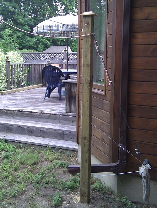
North anchor, with post to raise the guy wire
The north guy anchor is (or was) a problem. The anchor is set low in house frame and, since this anchor is far from the tower, the guys were chest height near the back deck. This is an accident waiting to happen! My solution can be seen in the picture. I used a pressure-treated post to raise the effective anchor point above head height. It is not enough to just run the guy wire through the top of the post. I used ¼" wire so that it would remain strong when bent at entry and exit points (and harder to cut). The post must also be stabilized since otherwise the guy tension, especially as the tower rocks in the wind, would bend the post forward and down. The main protection against this is the lower stay which holds the post in position. The redundant protection is use of clips at the entry and exit points to keep the guy wire fixed with respect to the post.

Redundancy is your friend. Guy hardware is cheap so don't scrimp: 2 clips at every guy termination; two set of guys, each of which alone will hold up the tower; oversize cable and insulators; etc. Rust, accident, weather and manufacturing defects do occur. Be ready for it.

Next Steps

Before putting up any antennas on the tower I would like to do a wind test. With the hot and humid weather this week there is very likely to be a good test very soon!

With that out of the way I plan to put up a temporary antenna for the summer. Come fall I will erect permanent low-band antennas. I will have more to say on these in future articles.

One of the benefits of a small tower rather than a mast it the ability to experiment with antennas without having to lower and raise the mast for each antenna or, worse, for each adjustment.